ERECA Stage Racer User manual

MI_STAR_EN.doc
SR Installation Manual EN
Indice : C
03/05/2019
1 / 15
ERECA SAS 75 rue d'Orgemont, 95210 SAINT GRATIEN France Tel +33 1 39 89 76 23 www.ereca.fr

MI_STAR_EN.doc
SR Installation Manual EN
Indice : C
03/05/2019
2 / 15
ERECA SAS 75 rue d'Orgemont, 95210 SAINT GRATIEN France Tel +33 1 39 89 76 23 www.ereca.fr
CONTENTS
CONTENTS........................................................................................................................................................2
1
Detailed DESCRIPTION..............................................................................................................................3
1.1
Connectors LOCATION ......................................................................................................................3
1.2
Connectors DESCRIPTION................................................................................................................4
1.2.1
General Purpose IN.........................................................................................................................4
1.2.2
General Purpose OUT.....................................................................................................................5
1.2.3
Analog AUDIO.................................................................................................................................6
1.2.4
Digital AUDIO..................................................................................................................................7
1.2.5
Serial ports ......................................................................................................................................8
1.2.6
Ethernet ports..................................................................................................................................8
1.2.7
HD VIDEO ports..............................................................................................................................9
1.2.8
Composite VIDEO ports..................................................................................................................9
1.2.9
OPTICAL access.............................................................................................................................9
1.3
Optional Connectors / Fuse / Part number .......................................................................................10
1.3.1
Description......................................................................................
Error! Bookmark not defined.
1.3.2
12 RS422 Pinout ............................................................................
Error! Bookmark not defined.
1.4
SUPERVISION..................................................................................................................................12
1.4.1
Password/Default ..........................................................................................................................12
1.4.2
IP address .....................................................................................................................................12
2
TECHNICAL SPECIFICATIONS...............................................................................................................13
3
APPENDIX: Cad file document.................................................................................................................15
Further information is available in the Stage Racer Technical Manual.
Please contact us for a copy.
MI_STAR_EN.doc
SR Installation Manual EN
Indice : C
03/05/2019
3 / 15
ERECA SAS 75 rue d'Orgemont, 95210 SAINT GRATIEN France Tel +33 1 39 89 76 23 www.ereca.fr
1 DETAILED DESCRIPTION
The stage racer base product is one 1RU rack solution ideally designed for base station fitment. For field
application a 4 to 5 RU fly case integration offers sufficient room for properly expending all the connections
on panel BNC and XLR sockets.
Rugged box integration is limited to 4 channels stage racer and subject to special order.
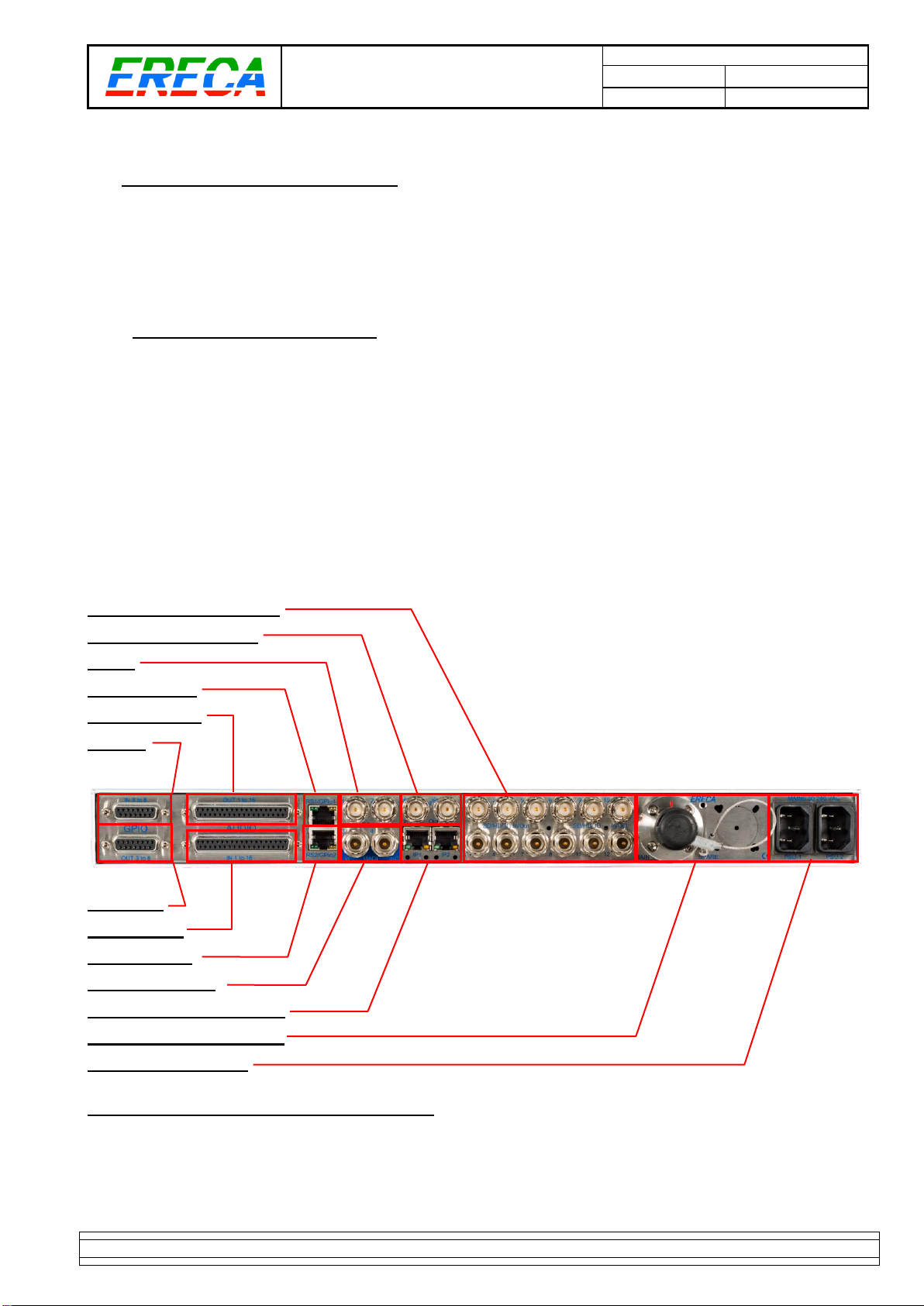
1.1 CONNECTORS LOCATION
The stage racer provides on one side all the connection of the base module signals. Some optional
connectors are located on the front face close to the LED display panel.
Connectors for each signal are described below:
•
D SUB 15 female sockets for GPIO 3-8.
•
D SUB 37 female sockets for analog audio.
•
RJ 45 for Serial signals (+ GPIO 1-2), Ethernet
•
BNC for PAL, HD SDI and AES.
•
LEMO 3K, NEUTRIK OpticalCon Duo/Quad, LC, SC/APC for optical ports.
•
IEC/CEE22, for main power.
4 to 12 HD SDI IN or OUT
1 PAL IN + 1 PAL OUT
2 AES
1 RS + 1 GPIO
16 AUDIO OUT
6 GP IN
6 GP OUT
16 AUDIO IN
1 RS +1 GPIO
2 AES or 1 MADI
1 GIGA ETHERNET (2 RJ)
OPTICAL CONNECTIONS
2 PSU 90 to 260 VAC
Figure 1 : STAGE RACER connector location
MI_STAR_EN.doc
SR Installation Manual EN
Indice : C
03/05/2019
4 / 15
ERECA SAS 75 rue d'Orgemont, 95210 SAINT GRATIEN France Tel +33 1 39 89 76 23 www.ereca.fr
1.2 CONNECTORS DESCRIPTION
The pinout for all the electrical access is described in the sections hereafter.
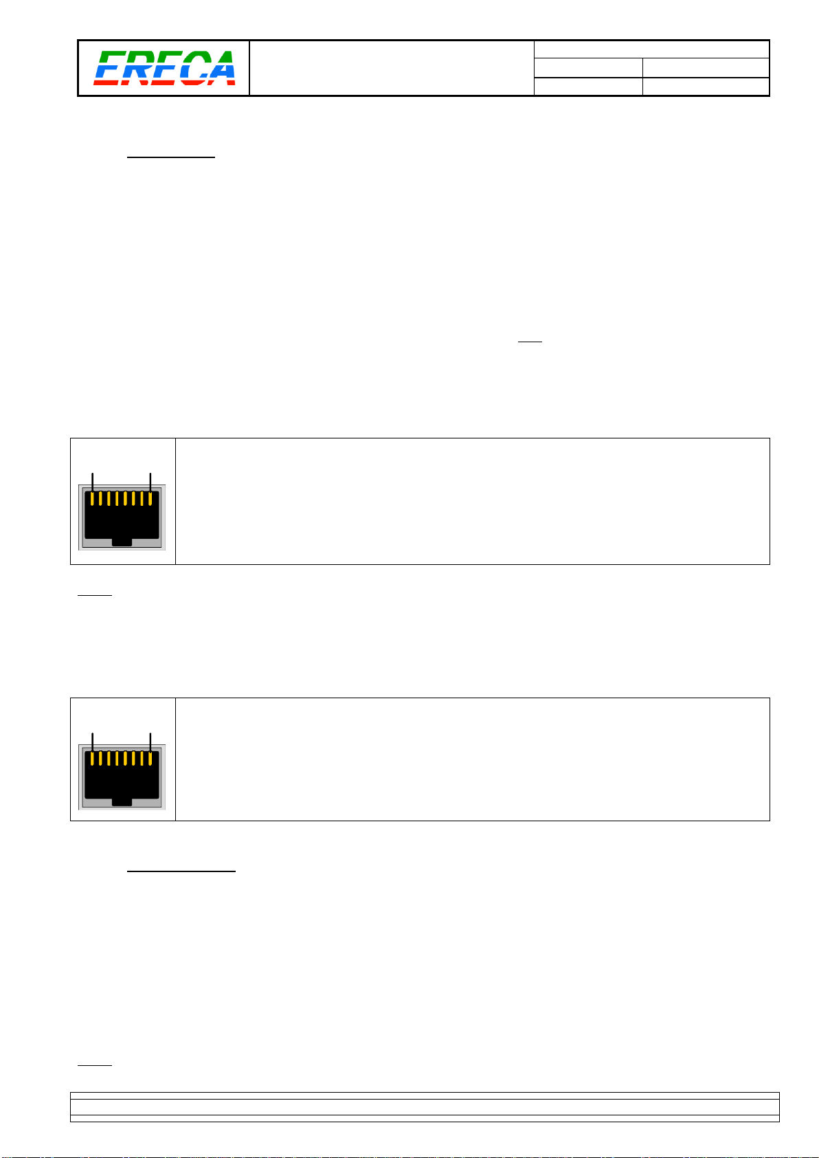
1.2.1 General Purpose IN
For forward product compatibility the GP IN section is split on two kind of connectors.
The input 1 and 2 are shared with each Serial signal transmission RJ 45 terminal, labeled "RS GPIO".
These inputs are protected by opto-coupler but are not floating, a grounding on the input pin triggers the GP-
IN.
18
1: GND
2: GP IN
3: RX RS 422 –or RX RS 232
4: TX RS 422 –or TX RS 232
5: TX RS 422 +
6: RX RS 422 +
7: GP OUT
8: GP OUT
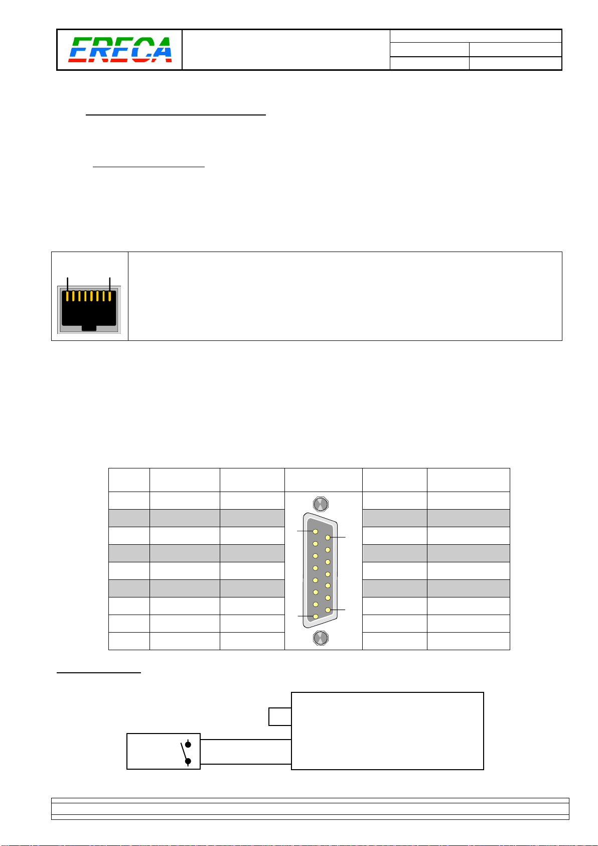
The input 3 to 8 are on one D-SUB 15 terminal female socket. Inputs are independent and electrically
isolated by opto-couplers. Each input is none polarized and feature an automatic 5mA current limitation
working with an input voltage of 5 to 24 Volts. User do not have to care of your wiring polarity for these ones.
Ground and power pins are available on the connector to ease interfacing with others machines especially if
the information is supplied by a dry contact, open connector, ground closure.
The 12 volts output of the stage racer is protected against external short circuit by a internal 100mA
resettable fuse (polyswitch) common to GPIN and GPOUT socket.
GP IN
N°
SIGNAL
Socket
contact
D SUB 15
GP IN
Socket
contact
SIGNAL
3
GP IN 3a
1
19
815
9
GP IN 3b
4
GP IN 4a
2
10
GP IN 4b
5
GP IN 5a
3
11
GP IN 5b
6
GP IN 6a
4
12
GP IN 6b
7
GP IN 7a
5
13
GP IN 7b
8
GP IN 8a
6
14
GP IN 8b
GND (0V)
7
15
+ 12V 100 mA
GND (0V)
8
Example: GP IN 3 (with dry contact, ground closure, open collector drive).
GP OUT
STAGE RACER
GP IN D SUB 15 terminal IN 3
9
1
0 V
+12V
7
15

MI_STAR_EN.doc
SR Installation Manual EN
Indice : C
03/05/2019
5 / 15
ERECA SAS 75 rue d'Orgemont, 95210 SAINT GRATIEN France Tel +33 1 39 89 76 23 www.ereca.fr
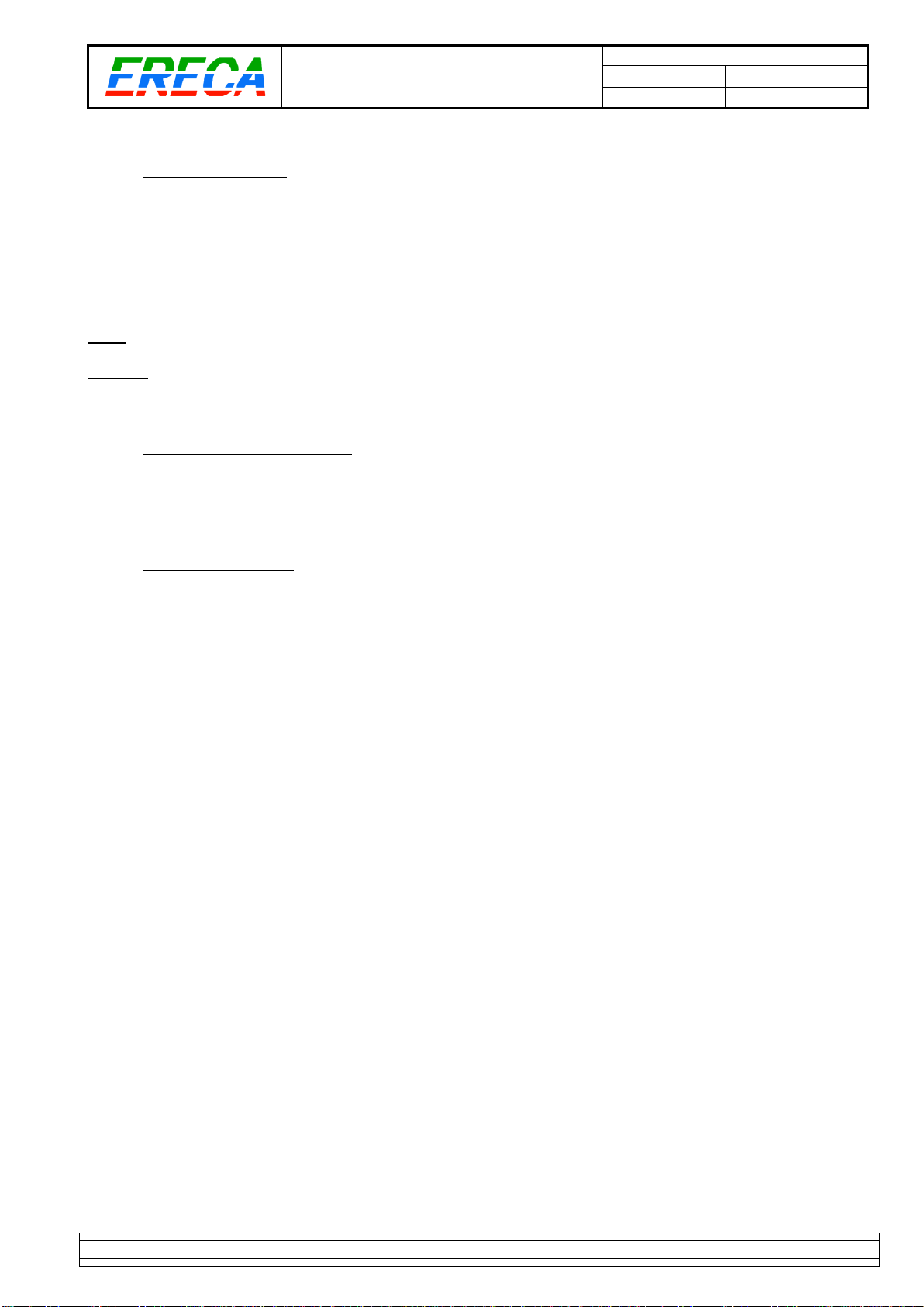
1.2.2 General Purpose OUT
For forward product compatibility the GP OUT section is split on two kind of connectors.
The output 1 and 2 are shared with each Serial signal transmission RJ 45 terminal, labeled "RS GPIO".
These outputs are on floating dry contact relays with 50 Volts AC/DC and 0.25 A switching capacity.
The relay is open if the corresponding remote input is not triggered.
18
1: GND
2: GP IN
3: RX RS 422 –or RX RS 232
4: TX RS 422 –or TX RS 232
5: TX RS 422 +
6: RX RS 422 +
7: GP OUT
8: GP OUT
The input 3 to 8 are on one D-SUB 15 terminal female socket. These outputs are also on floating dry contact
relays with 50 Volts AC/DC and 0.25 A switching capacity. The relay is also open if the corresponding
remote input is not triggered.
Ground and power pins are available on the connector to ease interfacing with others machines especially if
the driven machine need a voltage information rather than a contact closure.
The 12 volts output of the stage racer is protected against external short circuit by a internal 100mA
resettable fuse (polyswitch) common to GPIN and GPOUT socket.
Relay
N°
SIGNAL
Socket
contact
D SUB 15
GP OUT
Socket
contact
SIGNAL
3
GP OUT 3a
1
19
815
9
GP OUT 3b
4
GP OUT 4a
2
10
GP OUT 4b
5
GP OUT 5a
3
11
GP OUT 5b
6
GP OUT 6a
4
12
GP OUT 6b
7
GP OUT 7a
5
13
GP OUT 7b
8
GP OUT 8a
6
14
GP OUT 8b
GND (0V)
7
15
+ 12V 100 mA
GND (0V)
8
MI_STAR_EN.doc
SR Installation Manual EN
Indice : C
03/05/2019
6 / 15
ERECA SAS 75 rue d'Orgemont, 95210 SAINT GRATIEN France Tel +33 1 39 89 76 23 www.ereca.fr
1.2.3 Analog AUDIO
1.2.3.1 Pinout
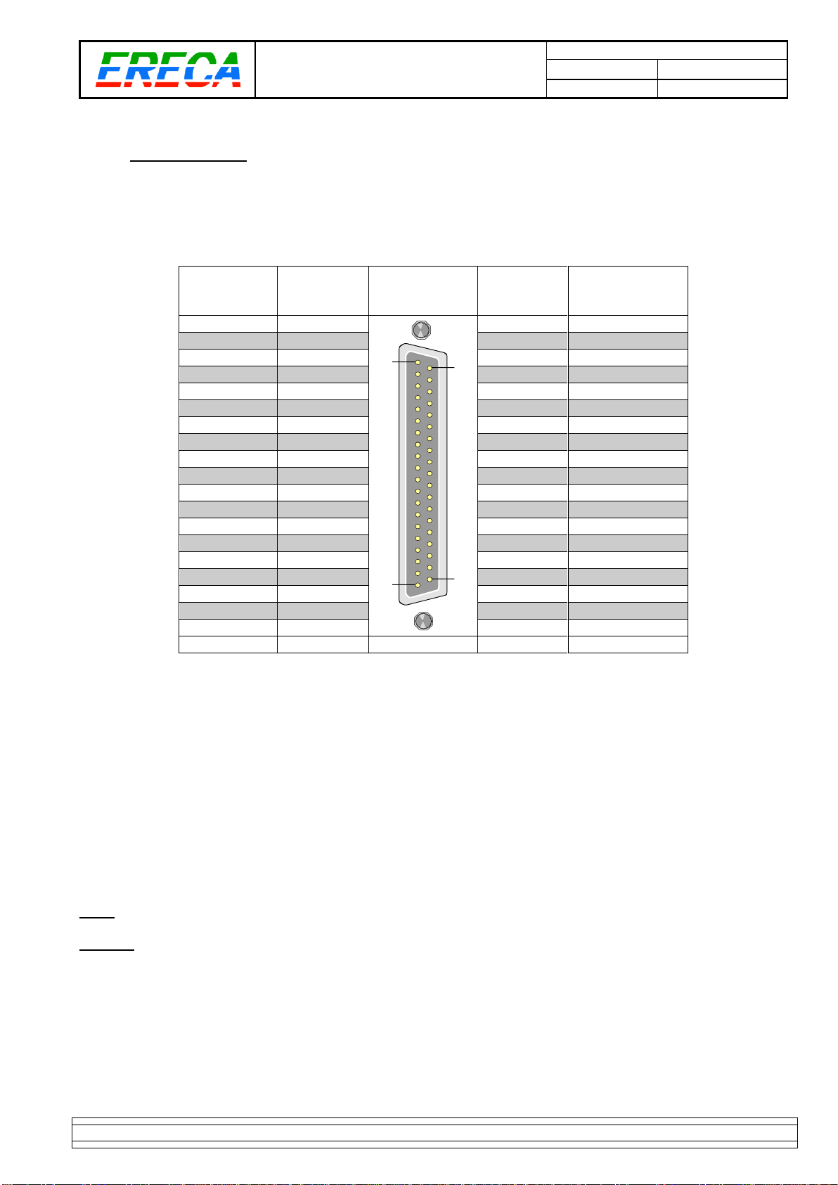
One D SUB 37 pin female socket provide the access to the 16 balanced analog AUDIO IN.
One D SUB 37 pin female socket provide the access to the 16 balanced analog AUDIO OUT.
SIGNAL
Socket
contact
D SUB 37
AUDIO
In/Out
Socket
contact
SIGNAL
AUDIO 1 +
1
120
19 37
20
AUDIO 1 -
AUDIO 2 +
2
21
AUDIO 2 -
AUDIO 3 +
3
22
AUDIO 3 -
AUDIO 4 +
4
23
AUDIO 4 -
AUDIO 5 +
5
24
AUDIO 5 -
GND
6
25
GND
AUDIO 6 +
7
26
AUDIO 6 -
AUDIO 7 +
8
27
AUDIO 7 -
AUDIO 8 +
9
28
AUDIO 8 -
AUDIO 9 +
10
29
AUDIO 9 -
AUDIO 10 +
11
30
AUDIO 10 -
GND
12
31
GND
AUDIO 11 +
13
32
AUDIO 11 -
AUDIO 12 +
14
33
AUDIO 12 -
AUDIO 13 +
15
34
AUDIO 13 -
AUDIO 14 +
16
35
AUDIO 14 -
AUDIO 15 +
17
36
AUDIO 15 -
GND
18
AUDIO 16 +
19
37
AUDIO 16 -
1.2.3.2 Audio option location
For units equipped with the 8 microphones gain block, the gain block is installed in the “RX” unit.
The gain blocks are connected to channels 8 to 16.
Thru the web server each 8 to 16 input can be amplified with a gain ranging from 9 to 60 dB (3dB steps) with
or without Phantom power supply.
If the gain on a channel is not wanted the gain block could be totally bypassed and this input recovers the
+18 dBm max input level.
The phantom power capacity is 10mA for each channel.
Note: To setup the gains remember to log on the RX unit.
Caution: Beware of the input phantom power, after switching off the phantom power the 48Volts will still be
present for a significative amount of time on the inputs, time needed by the inputs capacitor to discharge.
MI_STAR_EN.doc
SR Installation Manual EN
Indice : C
03/05/2019
7 / 15
ERECA SAS 75 rue d'Orgemont, 95210 SAINT GRATIEN France Tel +33 1 39 89 76 23 www.ereca.fr
1.2.4 Digital AUDIO
Digital audio is available on true 75 Ohms BNC sockets.
The total capacity of the stage racer is 4 simultaneous bidirectional AES signals. Thru the web server the
AES 3 and 4 could be turned to MADI, Respectively Madi IN on port 3 and Madi OUT on port 4.
Caution: Avoid connecting 50Ohms plugs it will damage the socket central pin causing costly repair
especially it this one is on the lower part of the connector side.
1.2.4.1 Bidirectional AES
Each AES port is internally equipped with a 2-4 wire converter connected to a fully bidirectional transmit
path to the remote stage racer.
This allow to interconnect talkback panels working in a bidirectional manner on one 75 Ohms coax. The
ports still can be used without configuration to transport unidirectional signal, no setup needed for channel
direction.
Note1: For the internal 2-4 wire converter correct behavior the source/terminal impedance of the machine
connected to the AES ports must be 75 Ohms.
Note2: The bidirectional function of the device constraint the design specially to provide an accurate AES
activity led display and avoid signal loop if port impedance is not 75 ohms. The internal FPGA seeks for
AES3 audio XYZ preamble at 48 KHz to light the corresponding AES Led and enable transmission in this
direction. Basically, the equipment is able to transmit 44.1 and 48 KHz audio, in the other case the detection
scheme will prevent transmission. Please ask for a product evolution if this stuck your application.
1.2.4.2 MADI transmission
When selected through the web server, MADI Is transmitted instead of 2 AES signals. The MADI signal
applied to port 3 of a device is output on port 4 of the remote equipment.
The MADI clock information is transmitted along the MADI signal, at receiving side the original clock is
precisely regenerated and MADI data delivered accordingly to this clock. Thus, the transmission is clock
conservative, so if the MADI machine used is able to synchronize on the MADI payload, you do not have to
carry a parallel wordclock signal thru another channel of the stage racer.
The MADI output VCXO capture range is +/- 100 ppm.
Note: If more MADI signals are needed it can be passed thru the Video channels by simply selecting the
right channel direction and bypassing the corresponding reclocker.
MI_STAR_EN.doc
SR Installation Manual EN
Indice : C
03/05/2019
8 / 15
ERECA SAS 75 rue d'Orgemont, 95210 SAINT GRATIEN France Tel +33 1 39 89 76 23 www.ereca.fr
1.2.5 Serial ports
Two multiprotocol RS232/422/485 serial signals are transmitted in standard by the equipment.
The supported datarate of each signal is about 250Kbds.
The setting of the serial protocol is done within the web server of the STAGE RACER.
1.2.5.1 RS422/485
The RJ 45 connector provide 1 differential pair for RS422 transmit and 1 differential pair for RS422 receive.
To build half duplex RS485 transmission just bridge pins 3 with pin 4 and pin 5 with pin 6.
For RS485 also setup the corresponding Baud rate within the web server to enable the stage racer to
manage output impedance at the right serial byte duration.
Refer the Shield to pin 1.
18
1: GND (Shield)
2: GP IN
3: RX RS 422 –(Stage racer electrical OUTPUT)
4: TX RS 422 –(Stage racer electrical INPUT)
5: TX RS 422 + (Stage racer electrical INPUT)
6: RX RS 422 + (Stage racer electrical OUTPUT)
7: GP OUT
8: GP OUT
Note: For RS 485 Telex/RTS talkback panels please ask ERECA for wiring tip.
1.2.5.2 RS232
Refer The RS 232 signal ground to pin 1. Leave pins 5 and 6 unconnected.
18
1: GND (Ground ref/Shield)
2: GP IN
3: RX RS 232 –(Stage racer electrical OUTPUT)
4: TX RS 232 –(Stage racer electrical INPUT)
5: Do not connect
6: Do not connect
7: GP OUT
8: GP OUT
1.2.6 Ethernet ports
The stage racer offers 2 Gigabit ethernet ports separated by internal VLANs, the 2 ports are transmitted
simultaneously on a single 1Gbs trunk.
The 2 ports are separated with 802.3AD VLANs. This VLAN setup takes care of your customer VLANS by
adding a service tag on input frames and removing this service tag on transmitted (output) frames. Basically,
the traffic held by the stage racer is considered 100% as payload so all your network setup won’t be
affected.
Networked audio (Ethersound / Dante / Ravenna) are correctly transmitted by the stage racer.
Note: The stage racer admin web server is accessible on PORT 1.
MI_STAR_EN.doc
SR Installation Manual EN
Indice : C
03/05/2019
9 / 15
ERECA SAS 75 rue d'Orgemont, 95210 SAINT GRATIEN France Tel +33 1 39 89 76 23 www.ereca.fr
1.2.7 HD VIDEO ports
Depending on the option chosen at order time the stage racer is equipped with 4, 8 or 12 video channels.
The signal direction of each channel is defined thru the web server into interface. The configuration is held
on the “TX” machine and automatically forwarded to the “RX” machine.
For MADI or SDTI signals each reclocker can be individually bypassed.
Note: Take care of the port numbers, grouped 4 by 4 in square for the 4/8/12 channels option management.
Caution: Avoid connecting 50Ohms plugs it will damage the socket central pin causing costly repair
especially it this one is on the lower part of the connector side.
1.2.8 Composite VIDEO ports
A bidirectional PAL / SECAM / NTSC / Tri-level sync compatible is transmitted thru the stage racer.
Minimal latency and high-quality process with +/-3dB AGC input, 2x over sampling and 10 bits digital filtering
and transmission is also provided for this signal often use as Genlock.
1.2.9 OPTICAL access
1.2.9.1 Standard
The stage racer uses only two fibers for signals transmission.
The STAGE RACER is available with the following optical terminals:
- LEMO 3K,
- NEUTRIK OPTICALCON Duo,
- NEUTRIK OPTICALCON Quad,
- SC/APC,
- SC/PC,
- ST/PC
- LC.
For OpticalCon QUAD connectors the 2 remaining fibers are output on 2 SC/APC connectors located on the
front face. (Note: On some custom requirement theses connectors could be located on the connector side
installed in the “spare fiber” free space).
1.2.9.2 Redundant path
As an option, the STAGE RACER can transmit the signals on the fiber by two optical paths. In this case the
optical connection is duplicated.
The principle is based on Master and Slave path. In normal optical conditions the master path is used and
the slave data path is monitored for good health. In the occurrence of master path failure, the slave path is
used with minimal transmitted perturbation.
When master path is repaired the equipment will detect it and automatically revert on the master path.
In the event of an OpticalCon Quad stage racer, the two free fibers redundant path is also managed by built
in wideband optical switches following the stage racer master/slave path decision.
MI_STAR_EN.doc
SR Installation Manual EN
Indice : C
03/05/2019
10 / 15
ERECA SAS 75 rue d'Orgemont, 95210 SAINT GRATIEN France Tel +33 1 39 89 76 23 www.ereca.fr
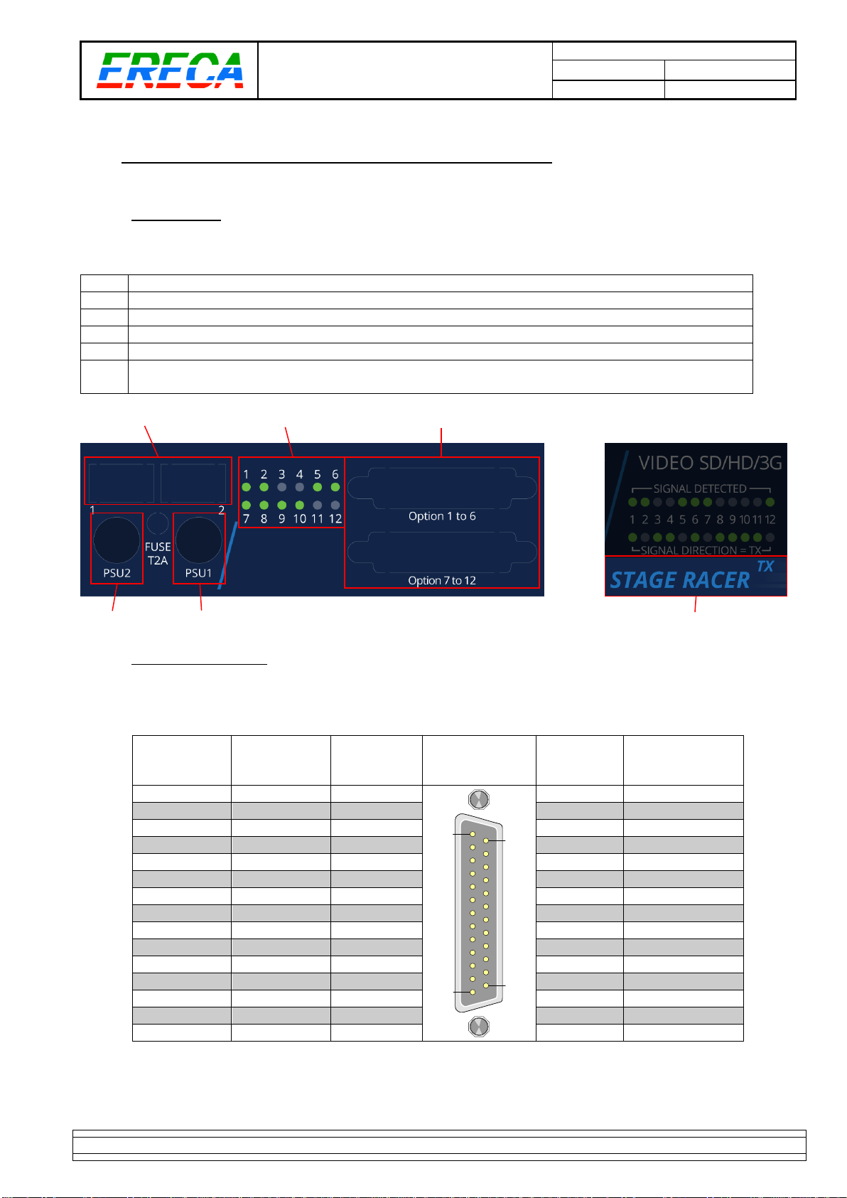
1.3 OPTIONAL CONNECTORS / FUSE / PART NUMBER
1.3.1 Description
The left part of the Display face provides:
1
Extra SC/APC terminal option (in case of OpticalCon Quad optical connections)
2
12 green LED status of the optional signal transmission (Eg:12 RS422 TX/RX activity)
3
Two D SUB 25 female sockets for the optional signal transmission (Eg:12 RS422)
4
Fuse for PSU1 (2 Amperes Slow Blow 5*20mm fuse)
5
Fuse for PSU2 (2 Amperes Slow Blow 5*20mm fuse)
6
(Video section)
Product information, a STAGE RACER is composed of 1 STAR TX + 1
STAR RX:
1 2 3
4 5 6
1.3.2 12 RS422 Pinout
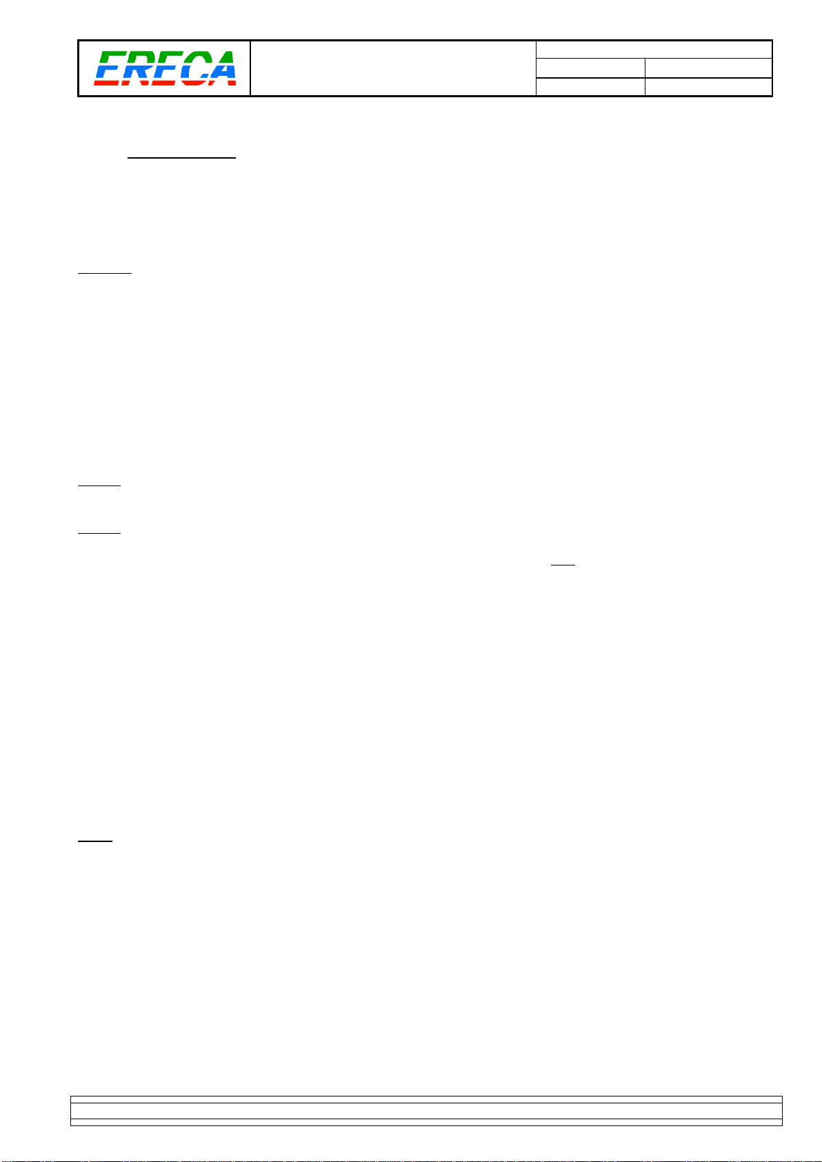
One D SUB 25 pin female socket provide the access to the extra RS422 channels 1 to 6.
One D SUB 25 pin female socket provide the access to the extra RS422 channels 7 to 12.
Channel
SIGNAL
Socket
contact
D SUB 25
RS422 1to6 &
RS422 7to12.
Socket
contact
SIGNAL
1 and 7
IN 1/7 -
1
1
25
14
13
14
IN 1/7 +
1 and 7
OUT 1/7 +
2
15
OUT 1/7 -
2 and 8
IN 2/8 -
3
16
IN 2/8 +
2 and 8
OUT 2/8 +
4
17
OUT 2/8 -
3 and 9
IN 3/9 -
5
18
IN 3/9 +
3 and 9
OUT 3/9 +
6
19
OUT 3/9 -
all
GND
7
20
IN 4/10 -
4 and 10
IN 4/10 +
8
21
OUT 4/10 +
4 and 10
OUT 4/10 -
9
22
IN 5/11 -
5 and 11
IN 5/11 +
10
23
OUT 5/11 +
5 and 11
OUT 5/11 -
11
24
IN 6/12 -
6 and 12
IN 6/12 +
12
25
OUT 6/12 +
6 and 12
OUT 6/12 -
13
Pinout is the same for the two connectors. It is strongly recommended to connect the shield of the signals
transmitted to the GND pin.

MI_STAR_EN.doc
SR Installation Manual EN
Indice : C
03/05/2019
11 / 15
ERECA SAS 75 rue d'Orgemont, 95210 SAINT GRATIEN France Tel +33 1 39 89 76 23 www.ereca.fr
Each LED summarize the Input and Output signal activity on the corresponding channel.
Each signal activity is also reported on the web browser “signal status” page.
Each differential input is not 120Ohms loaded internally for optimum compatibility with transmitted protocols.
If impedance matching is needed a small SFR16 resistor could be added directly on the D SUB pints
together with the signal wire.
The 12 extra RX 422 supported datarate of each signal is about 25Kbds. This option is totally independent
and do not affect the 2 standard serial interfaces.
Note: For RS 485 Telex/RTS talkback panels please ask ERECA for wiring tip.
Note: As the differential inputs are unloaded internally a small crosstalk should happen on the adjacent
channel only if it is unused and left floating.

MI_STAR_EN.doc
SR Installation Manual EN
Indice : C
03/05/2019
12 / 15
ERECA SAS 75 rue d'Orgemont, 95210 SAINT GRATIEN France Tel +33 1 39 89 76 23 www.ereca.fr
1.4 SUPERVISION
1.4.1 Password/Default
Note: If IP add is lost, press S1 switch on the front face for 5 seconds, the unit will revert to default settings.
1.4.2 IP address
Setup the IP address of the unit, after validation with the password the unit instantaneously switches to the
new IP settings, an “internet” link route the user to the new address.
Default IP: 192.168.1.245 on a TX / 192.168.1.246 on a RX / NetMask 255.255.254.0.
Further information is available in the Stage Racer Technical Manual.
Please contact us for a copy.

MI_STAR_EN.doc
SR Installation Manual EN
Indice : C
03/05/2019
13 / 15
ERECA SAS 75 rue d'Orgemont, 95210 SAINT GRATIEN France Tel +33 1 39 89 76 23 www.ereca.fr
2 TECHNICAL SPECIFICATIONS
Optical
Dynamic range:
10 dB for the 12 channels (11.5 dB/8Ch, 13 dB/4Ch) pathological signal.
Connector:
NEUTRIK OpticalCon DUO or LEMO 3K (EDW / FXW)
Video SD/HD
Number, connector:
4 to 12 channels on BNC (Each channel is direction configurable).
Direction setting
Internal Web Server.
Impedance:
75 Ω
Standard:
SDI, ASI, HD, 3G
Reclocker bypass available for SDTI or MADI compatibility
Amplitude:
Input: cable equalization (140 m Belden 1694A for 3G), Output: 800 mV pp
Return loss:
Better than - 15 dB for 0 to 1500 MHz and better than - 10 dB for 1500 to 3000 MHz
Analog Video / GL
Number, connector:
1 Bidirectional, 2 BNC
Standard:
PAL, SECAM, NTSC, Tri-level ( Bi / Tri level auto sense )
Impedance:
75 Ω
Bandwidth:
> 5.8 MHz at +/- 0.2 dB
Differential Gain/ Phase
< 1%, < 1°
Group delay:
< 10 ns
SNR:
> 67 dB (CCIR567)
Analog Audio
Number, connector:
16 bidirectional channels
Rugged box: 4 on XLR / 4 on one SUB D 25 socket; for 1U rack all on SUB D 37
Impedance:
Input: 10 KΩ differential (non floating), Output: 20 Ω differential (non floating)
Amplitude:
+4 dBm nominal (saturation at + 18 dBm)
Bandwidth:
50 Hz to 15 KHz at +/- 0.5dB, (20 Hz to 20 KHz at -3 dB)
Distortion:
0.05% at 1Khz +18 dBm
Signal to noise ratio:
90dB, "A" weighted
Digital audio
Number, connector
4 AES bidirectional
(Riedel panel compatible
)
OR
1 MADI (
AES10
) + 2 AES bidirectional
(Riedel panel compatible)
Bitrate
Up to 48 KHz AES audio / 125 MBs full bandwidth for MADI, clock phase conservative
Impedance / Connector:
75 Ω, BNC
Setting:
Internal Web Server.
Data
Number, connector:
2 bidirectional channels, 1 RJ 45 socket per channel.
Protocols:
RS485, RS422, RS232
Data rate:
0 to 230 Kbd/s
Setting:
Internal Web Server.
Ethernet
Number, connector:
2 channels on VLAN (802.1.ab), RJ45 Socket
Protocols:
10, 100 or 1000 mb/s, Full or Half-duplex (Auto), MDI or MDI-X (Auto)
GPIO
Number, connector:
8 bidirectional GPIO contacts 6 on D-SUB plus 1 GPIO along each DATA RJ45 connector
Output:
Relay (dry contact). ‘Common’ – ‘Normally Open’ terminals for each relay
Input:
Floating on the D-SUB, Input pin grounding on RJ45.
MI_STAR_EN.doc
SR Installation Manual EN
Indice : C
03/05/2019
14 / 15
ERECA SAS 75 rue d'Orgemont, 95210 SAINT GRATIEN France Tel +33 1 39 89 76 23 www.ereca.fr
Powering
Consumption:
20 Watts per side
Low voltage source:
8 to 20 VDC, XLR 4 pins connector, protected by 5*20 mm standard internal fuse
Mains source:
From 90 to 260 VAC / 47 to 63 Hz
Dual supplies in the 1U rack
Mechanical
Rugged model:
Die cast strong aluminum case, size 335 x 235 x 111mm excluding connectors and handles
Rack model:
1 RU 19” rack, depth 300mm excluding connectors.
Cooling:
Internal fan / (Case walls acting as Heat sink / No dust entry guarantee for the RUGGED )
Operating Temp range:
From -20 to + 60°C. (Avoiding direct sun exposition)
Signaling / Setup
Transmitted signals:
1 LED per signal
Alarms
1 LED per technical alarm (Power supply / Temperature / Fiber alarm )
Remote
All signal presence / alarm are reported trough the web server.
Settings
All settings are done trough the web server.
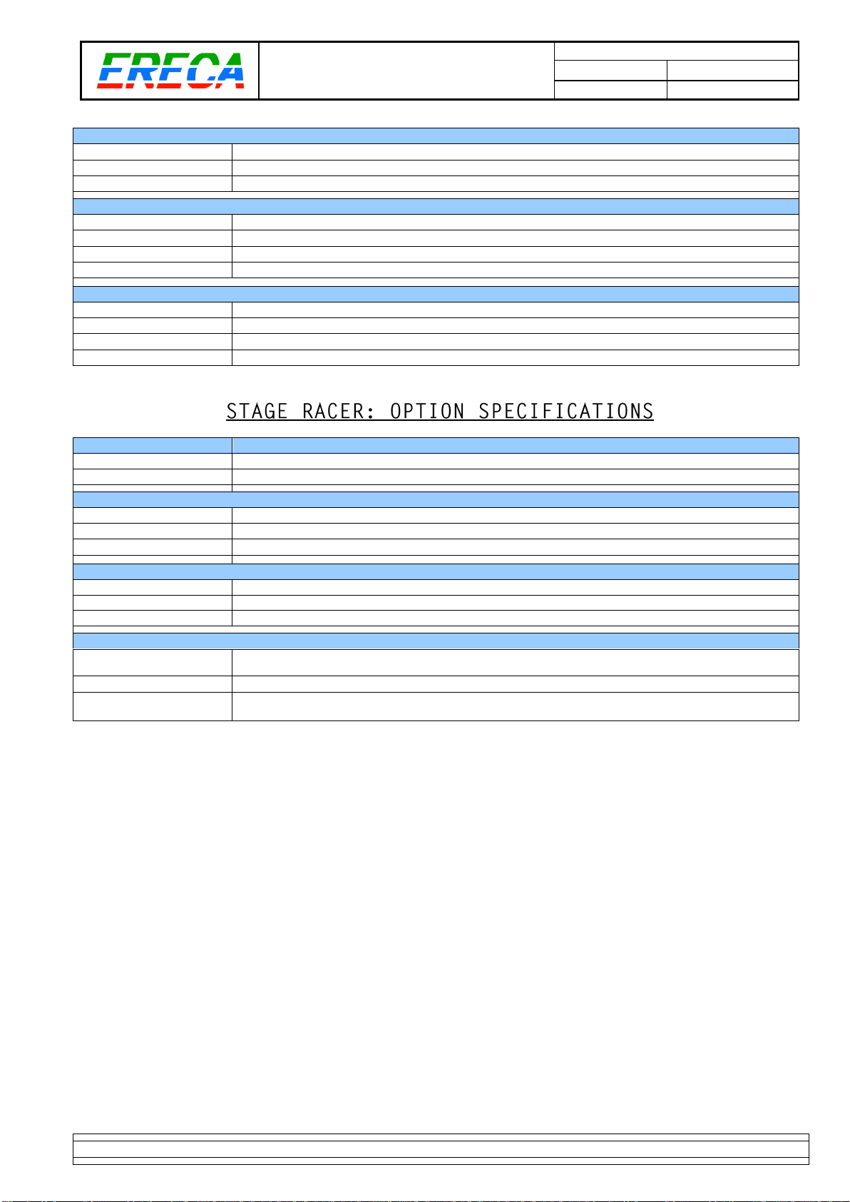
Optical OPTION
Redundant path:
Double optical transmission with automatic optical path selection.
Optical losses:
1.8 dB per link for optical switching
Analog Audio OPTION
Input:
Microphone input gain block on 8 of the 16 channels
Mic input, Gain:
From 10 to 60 dB, Bypass and Tunable by 3 dB steps, through internal Web Server.
Phantom power:
48 volts switchable , through internal Web Server, Source Impedance 6.8 KΩ
Data OPTION
Number, connector:
12 bidirectional channels, one SUB D 25 for 6 channels (1U rack version).
Protocols:
RS422
Data rate:
0 to 19.2 Kbd/s
Remote Powering OPTION on LEMO 3K
Power topology:
Power source: 1U rack STAGE RACER
Powered device: Rugged STAGE RACER box
Camera powering:
12VDC, 30 W available on XLR 4
Performance with
AWG16 SMPTE cable:
2.5 km for rugged STAGE RACER box alone (no camera remote powered)
950 m for rugged STAGE RACER box + 30W camera load
Nota: Due to space limitation on the rugged box connector area; please contact ERECA Company for your application.

MI_STAR_EN.doc
SR Installation Manual EN
Indice : C
03/05/2019
15 / 15
ERECA SAS 75 rue d'Orgemont, 95210 SAINT GRATIEN France Tel +33 1 39 89 76 23 www.ereca.fr
3 APPENDIX: CAD FILE DOCUMENT
Table of contents


