manuals.online logo
Brands
  1. Home
  2. •
  3. Brands
  4. •
  5. Marti
  6. •
  7. Transmitter
  8. •
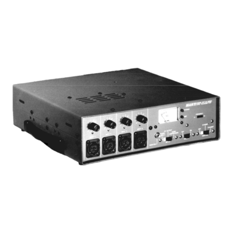
  9. Marti RPT-25 User manual

Marti RPT-25 User manual

www.SteamPoweredRadio.Com
\J
,
PT-2
5
T
RANSMITTF.R
:
,
www.SteamPoweredRadio.Com
MARTI
E\.ECTIWNICS,
INC
P.O.
Box
G61
1501
N.
Mo
ln
SL
reet
Cleburne,
Texas
76
0
31
HPT-2
5
TRANSMITTF.R
I
WARRANTY:
Exceiat 01
ot'-wi,e
provided
In
tni•
1ect,on,
t
he
equipmonl
d,ncribod
heroin
i,
,old
under
tho
following
guor•ntoe,
Marti
ogreos
to
repoir
or
replace
wit
hon
a
en•
(l)
yoor
pe,lod
and
without
charge,
ony
oquipmen!
or
ports
which
are
olofective
01
lo
wo~,nonshlp
or
mo!orlol ancl which
ort1
returned
to
Marti
o!
ih
factory,
lrctnsportotion
prepaid
ond
properly
lnaurod,
provided,
{o) Notice of
the
clol,ned
defect
it
given
Mortl within
one
(1)
year
from
dote
appearing
on
invoice
and
goods
ore
returned
in
accordonco
wi1h
Marti
in1truction1.
(b)
Equ
i
pment,
occeuorle
s,
tub
..
and
ba11erie1
nol
marwfoctured
by
Marti aro subject
10
only
,uch
od-
ju1tmenh
01
Marti
may
obtain
from
the
1upplior
lheroof.
(c)
Equipment
or
occeuorles
1holl
not
bo
deemed
to
kie
defective if,
ofter
exominolion
by
Marti
or
ill
appointed
repro,ontotlve,
the
equipment
evitlence,
domoge
from moi1ture,
Improper
ha
n-
dling,
ln110ll01lon
Of
operation.
(d)
In tho
ovenl
tho! Marti
11
required
to
demon11rate
equipment
capability
either
01
to
,pecilicatlons
or
dofec;t1 In
part,
er
workman1h
ip
and
whe
ro
it
11
found
that
tho
equipmonl
meeh
1pecification1,
Marti
1hall be
entitled
to
collect
oil
AOsonablt
upeme1
from
the
lluyer including
but
not limited
to,
travel,
per
di
em
living expen1e1
oi,d
hourly
wage
rote,
which
have
boon
e1tabll1hed
by
Ma
r
ti
e1nd
which oro in eAec1
at
tho
tlme.
Marti lurr+.or
gvorantu,
!hat
ony
radio
lranomt"9<
de1crlbed
her
ein will
deli
v
er
1pecified
radio
frequency
power
ou
tput
at
the
ontonno
I.ad
whon
connocled
to
o 1ultable
lood
,
but
,uch
guaronteo
sholl
not
be
co
n-
strved
o, Q
guoron!ee
of
any
definite
coverage
«
range
of
,oid
apporo!v,.
Tho
guoron
!
ee
of
!he,e
poro•
graph,
i1
void If
equipmem
i1
altered
or
repolrod
by
other,
!
hon
Mart
i
or
I
ts
outhorited
M1rvice
Repre-
1on!otive,
o,
unleu
,pecif,colly ou!hoti%od
Ii<
writing
by
Marti.
No
other
worron!
l
e,
, e
xpressed
or
impliod,
shall
be
ofl,plicoblo
lo
•ny
.qu
i
pment
said
herevndor,
ond
the
foregoing
,hall
con1!i!uto
the
Bu
y
er's
,a
le
right
ond
remedy
under
th•
Ggreem
ents conlcJinttd
i11
thi1
earagroph
. In
no
oven! 1
hall
Marti
hove
ony
liab
ility
f.or
contequan!ial
oomage,,
or
for
1011,
clornoge
or
expen
,e directly
or
ind
irectly ari
,ing
from the
ute
of
the
p,odvcll,
or
any
inability
lo
UH
,1,.,..
oilher
sepa
r
ately
or
in
co
m
bination
with
other
equ
i
pme
nt
or
ma
torlol1,
or
from
°"Y
o~r
cause.
www.SteamPoweredRadio.Com
RPT-25
REMOTE
PICK
UP
TRANSMITTER
S.P-EC
IF
IC-AT
IONS
Application----------------------
Broadcast
Remote
Pick
Up.
Frequency---------
---------------
-450.001 -
455
.95
MHz
.
Crystal
Multiplication-----------
36.
MARTI
ELECTRONICS
Cleburne,
Texas
FrequeRcy
Sta~ility-------~-----
Portable/Mobile:+
,0005%
-30°C
to
+50°C.
1;'wo
(2)
minutes
are
r;quired
~fter
application
of
stand-by
power
for
the
transmit
ter
to
be
in
toleranc€
when
operated
~ortable-mobile
at
temperature.5
below
-10°C
.
Base
Station:+
.00025%
-30°C
to
+50°C two
(2)
minutes
a.fter
initial
application
of
-st-and~hy
power.
Dual
Frequ~mcy
Oper
•
ation---------
Selectable
dual
freE!uency
operation
available
at
eKtra
cost.
Spurious
Emission--
--------------
Spurious
radiation
attenuated
more
than
60
DB
below
carrfer
ley.el.
RF
Output------------------------
Maximum
25
watts,
nominal
20
watts
into
50 ohms.
VSWR
Protection------------------
High
VSWR
will
not
damage
transmitter.
RF
Connector---------------------
UG-58A/U.
Temperature
Range----------------
-20°C
to
+45°C.
Modulation----
----
-------------
--
Model
---
Deviation
Emission
RPT-25P
1.5
KHz,.
10F3
RPT-25N2 5
KHz.
25F3
RPT-25R 9 -KHz.
50F3
RPT-25S
22,5
KHz.
100F3
Audio
Inputs------
,---
----
--
--·----
Four
-
inputs
are
provided
with
individual
mixing
·
gain
coatrels
.
three
of
the
inputs
are
for
micro-
phones
(one
push-to-talk)
and
one
input
accepts
balanced
600
ohm
line.
Audio
Input
Leve
l---
--
-- -
-----
---
Microphon
e
input
level
can
be
from
-70
DB
to
-45
DB,
Line
input
level
can
be
from
-20
DBM
to
+4
DBM
.
Audio
Input
Impedance------------
-Will
accept
microphones
from
150
to
600
ohms.
Line
input
600 ohms
balanced,
Audio
Connectors-·---------------
Inp
ut
No. 1 (XLR--4-31).
Input
Nos.
2,
3,
and
4
(XLR-3-3
1).
Power
Requirements-------·--------
115/230
volts
AC,
50/60
Hz.,
155
watts
transmitt-
ing,
30
watts
standby.
13.6
volts
DC
negative
ground.
7
amp
.
transmitting,
0,5
amp.
standby.
Modulation
Control---------------
Marti
CA-40
Compressor/Limiter
Module.
Selector
switch
for
measuring
audio
level,
compressor
gain
reduction,
RF
output,
etc,
Weight---------------------------
20
lbs.
net,
26
lbs.
gross
.
Dimensions-----------------------
6-k"
high
by 15
11
wide
by 12
11
deep.
NOTES:
(1)
Measured
through
4
KHz
. low
pass
audio
filter.
(2)
Pre-selector
recommend
ed
when
receiver
is
located
near
UHF
transmitter.
(3)
The
extremely
good
sel
ectivit
y
of
this
receiver
results
in
some
reduc-
tion
of
audio
response
and
increased
distortion
,
Ever
increasiqg
use
of
UHF
frequencies
dem
ands
this
selectivity
in
modern-receivers.
www.SteamPoweredRadio.Com
SECTION
I
GENERAL
1.1
Marti
Model RPT-25
and
RPT-40
Solid
State
Transmitters
are
designed
to
operate
in
the
Remote
Pickup
Broadcast
service
as
defined
in
Part
74,
Subpart
D,
of
the
FCC
Rules
and
Regulations.
The
suffix
letter
of
the
transmitter
indicates
the
FCC
fre-
quency
group
it
is
designed
to
operate
on.
These
are
as
follow:
MODEL
NO.
FREQUENCY
MHz.
RPT-25P
450.01-455.95
RPT-25N2
450.01-455.95
RPT-25R
450.01-455.95
RPT-25S
450.01-455.95
RPT-40K
152,87-161.
76
RPT-40L
166.25-170.15
BANDWIDTH
10
25
50
100
30
25
KHz.
COMPANION
RECEIVER
R-30/450
R-
30/450
R-50/450
R-100/450
R-30/150
R-30/150
These
transmitters
when
used
with
the
recommended
companion
receiver,
provide
a
re-
mote
broadcast
link
having
audio
quality
not
approached
by
conventional
voice
com-
munication
radio
equipment.
NOTE:
These
Marti
Transmitters
can
be
used
with
older
tube-type
Marti
Receivers
by
positioning
a
special
"Response"
switch
provided
on
the
top
side
of
the
transmitter
chassis.
This
"Response"
switch
is
normally
factory
set
to
"DFM"
position
for
use
with
New
Solid
State
Receivers
by
placing
this
switch
in
"PH"
position,
the
RPT-25
will
operate
with
the
MR-100/450
and
the
RPT-40
will
operate
with
the
MR-30/150
Receiver.
The
"Response"
switch
is
accessible
by
removing
the
transmitter
top
cover.
The RPT-25
and
RPT-40
transmitters
operate
from
both
115/230
volt,
50-60
Hz.
AC
commerical
power
and
11
to
14
volt
battery
(Negative
ground)
supply.
Four
audio
input
channels
are
provided
with
individual
mixing
gain
controls.
A
meter
and
selector
switch
are
provided
for
monitoring
and
adjusting
various
trans-
mitter
stages
as
well
as
audio
VU
level
and
audio
gain
reduction.
The
solid
state
audio
processing
technique
pioneered
and
proven
by
Marti
Electronics
in
hundreds
of
remote
pickup
broadcast
transmitters
has
been
applied
to
these
models,
resulting
in
the
highest
quality
possible,
consistant
with
transmission
bandwidth
and
other
fac-
tors.
www.SteamPoweredRadio.Com
.002
.002
ORANGE
I
OIA
018
0
IC·
CONNECTION FOR
115V.
OPERATION
R-SERIES
RECEIVERS
RED
ORANGE _BLACK
.002
01D
I
-BLACK
(TO
FUSE)
TO
CONVERT
FROM
U5
',(
IQ 230Y,;
I.
CUT JUMPER
FROM
A
TO
C.
2.
CUT JUMPER
FR
OM
BTO D.
3.
CONNECT JUMPER TO 8
AND
C.
4.
INSTALL
FUSE
OF
HALF THE
CURRENT
RATING USED
FOR
115
V.
'~
'
~
' ·1
z
'I
'---
.....
-t4§~a..
__
_
I I r---1.,_------11
]t-------c
1-------1r7
I I
I
OIA
_
BLACK
A.C. INPUT
018
0
IC
CONNECTION FOR
230
V.
OPERATION
01D
I
_
BLACK
(FUSE)
.002
DWG
.
NO.
700-110-2
MARTI
Glecir
onic:J,
Jnc.
115
V.
/
230
V.
CONVERSION
FOR
A-SERIES
RECEIVERS
www.SteamPoweredRadio.Com
2.1
UNPACKING
AND
INSPECTING
SECTION
II
INSTALLATION
This
equipment
was
packed
and
delivered
to
the
carrier
with
utmost
care.
Do
not
accept
shipment
from
carrier
which
evidences
damage
or
shortage
until
the
carrier's
agent
endorses
a
statement
of
the
irregularity
on
the
face
of
the
car-
rier's
receipt.
Without
documentary
evidence,
a
claim
cannot
be
filed.
Unpack
equipment
immediately
upon
receipt
and
thoroughly
inspect
for
concealed
damage.
If
damage
is
discovered,
ceas~
further
uRpacking
and
request
immediate
inspection
by
local
agent
of
carrier.
A
written
report
of
the
agent's
findings,
with
his
signature
is
necessary
to
support
claim.
Check
your
shipment
against
the
shipping
papers
for
possible
shortagP
Do
not
discard
any
packing
material
until
all
items
are
accounted
for.
Small
items
are
thrown
away
with
packing
material.
2.2
PLACEMENT
OF
EQUIPMENT
Install
rack-mounted
equipment
in
a
well-ventilated,
well
grounded
and
shielded
rack
cabinet.
Do
not
locate
solid
state
equipment
in
a
rack
above
tube-
type
eq
uipment
which
produces
high
temperatures.
Problems
can
also
be
avoided
by
locating
this
unit
away
from
other
equip-
ment
which
has
transformers
that
produce
strong
magnetic
fields.
These
fields
can
induce
hum
and
noise
into
the
Marti
Equipment
thus
reducing
performance.
Also,
strong
radio
frequ
e
ncy
fields
should
be
avoided
where
possible,
www.SteamPoweredRadio.Com
SECTION
II
INSTALLATION
CONTINUEDa
2.3
Mobile
Inatallation
of
R.PT-25
and llPT-40
A
typical
automativa
inatallation
la
shown on drawing 700-017-1.
The
transmitter
is
located
in
the
trunk
compartment and
is
remotely,
controlled
by
the
Marti
TPS-TC-1
control
unit
located
near
the
driver.
CAUTION,
Thia equipment
la
for
use
in
12.6
volt
naaative
around
vehicles
only.
Reverse
polar-
ity
will
instantly
destroy
tranaistors.
The
step-by-step
procedure
for
automative
in-
stallations
is••
follow•~
2.3,1
Mount
the
TPS-TC•l
control
unit
to
the
automobile
control
console
at
a
point
convenient
to
the
operator.
The
two
anal•
mountina
brackets
may
be used
as
attached
to
the
control
box
for
shippin&
or
turned
outw,rd,
depending on
available
mounti~~
apace.
Mount
the
two
bracket•
to
the
■
elected
mounting
surface
by
drilling
two 5/32
inch
diameter
hole
■
1pacad
either
5
inches
or
7
inches
apart,
depending upon method
selected,
Mount
the
two
anal•
bracket,
uaina
two
of
the
No.
10 x
3/4
inch
metal
tappina
acrewa
1upplied
with
the
TPS•TC•l
control
kit,
Attach
the
control
box
to
the
bracket
uaina
the
lwo
Hex-Head
No.
10
x;
inch
screws
supplied.
2.3.2
Attach
the
mountina
rack
part
No.
700-136
to
transmitter
using
the
quick-re-
lease
futenera.
Place
the
transmitter
in
th'e
trunk
compartment
at
a
place
where
it
is
eaaily
inatalled
and removed. Note
that
apace
is
required
at
each end
of
the
transmitter
for
oper~tion
of
the
rack
fastener,.
Alao
provide
spaGe
at
the
rear
of
the
tran1mitt1r
for
air
circulation
around
the
heat
aiuk
and
attachment
of
the
power,
antenna
and
r1c1iv1r
conn,ctora.
Whan
the
proper
location
ia
determined,
note
the
location
of
the
tranamittar
mountina
rack.
a,leaae
the
rack
fastener,
remove
the
tran1mitter
without
ahiftina
the
correct
location
of
the
rack
and mark
the
location
of the three
acrew
hol11
iq
the trunk
floor.
Before
drillin&
or
punching
these
holes,
lift
the
carpet
or
mat and determine
that
the
hole
locationa
will
not
damage
any
part
of
the
vehicle.
If
in
the
cl•ar,
drill
the
three
,/32
inch
diameter
holes
and
attach
the
rack
uaina
three
No.
10
x
3/4
inch
metal
tappina
screws.
2.3.2
Mount
the
Littl1fu1a
Circuit
Breaker
(15
amp
ratln&)
within
10
inches
of
the
po1itive
terminal
of
the
battery.
The
negative
terminal
of
the
battery
must
connect
to
the
chauh
or
frame
of
th1 v1hic,
la.
2,3.4
In1tall
cablta batwe1n c~
n~
,~t
ora
in
trunk
compartment and
control
box
and
bet•
ween
trunk
and
circuit
br11k1r
••
ih
own
on
drawina
700-017•1,
S~
Ja
r, •
~•
•dio a
nd
•~
cable
■
by
at
le11t
3
feat.
www.SteamPoweredRadio.Com
INSTALLATION
CONTINUED:
2.3.5
Connect
the
red-White
No. 16
wire
from TPS-TC-1
box
to
the
"Accessory"
switch
of
the
vehicle.
2.
3
.6.
Connect
Black
No. 10
wire
from power
in
trunk
to
a good
electrical
(Bright
Metal)
ground
at
vehicle
chassis.
2.3
.7
Fasten
the
transmitter
to
the
rack
in
the
trunk
and
connect
the
XL-4-12C
four-pin
micrphone
plug
on
the
audio
cable
to
input
No.l
of
the
RPT-25
or
RPT-
40
transmitters.
2.3.8
Install
the
mobile
antenna
and
connect
to
antenna
connector
Jl
on
back
of
transmitter.
NOTE:
ALWAYS
MAKE
SURE
ANTENNA
IS
CONNECTED
BEFORE
POWER
IS
APPLIED
TO
TRANSMITTER.
2.3.9
Connect
the
Cannon GK-923-C-~
plug
on
the
remote
control
cable
to
the
mating
DC
power
receptacle
on
back
of
transmitter.
2.3.10
If
two-way
operation
is
desired
install
model FR-2527A
VHF/UHF
mobile
re-
ceiver
at
the
desired
place
under
the
vehicle
dash,
then
install
the
connecting
coax
cable
from
receiver
to
J3
(Receiver)
jack
located
on
back
of
transmitter.
Note
that
the
"BNC"
connector
end
of
cable
goes
to
the
receiver.
Both power and
antenna
are
supplied
to
the
receiver
through
the
cable.
2.3.11
Connect
the
short
red
No. 10
wire
from
the
Littlefuse
circuit
breaker
to
the
Positive
terminal
of
the
12
volt
vehicle
battery.
2.3.12
Plug
microphone
into
the
4-pin
microphone
connector
on
the
TPS-TC-1
control
unit.
The
installation
is
now
ready
for
testing.
Refer
to
Operating
Instructions
in
Section
111.
2.4
Connecting
Equipment
for
Stationery
Remote
Broadcast
Remote
Pickup
broadcasts
from
sporting
events
etc.
occurring
from a
stadium,
coliseum,
gymnasium
or
auditorium
involve
several
aspects
of
equipment
location.
The
transmitter
normally
is
located
near
the
announcer
or
engineer
to
permit
access
to
the
gain
controls,
monitoring
jack,
and
metering.
Availability
of
115
volt
AC
power
is
an
important
consideration
in
locating
the
transmitter.
For
115
volt
AC
operation,
use
the
special
AC
adapter
cable
supplied
with
your
transmitter.
The
cannon
9-pin
connector
plugs
into
the
DC
power
conn
ecto
r on
the
back
of
the
RPT-25
and RPT-40
transmitter.
CAUTION:
ALWAYS
MAKE
'1'HIS
CONNECTION
BEFORE
PLUGGING
INTO
115
VOLT
AC
OUTLET.
www.SteamPoweredRadio.Com
CAUTION:
TO
PREVENT
ELECTRICAL
SHOCK
1
THE
ROUND
PIN
.
OP
THE
STANDARD
AC
PLUG
MUST
BE
CONNECTED
TO
A
PROPERLY
GllOUNDED
ELECTRICAL
OUTLET.
Some
station~
are
equipped
with
a Remote
Pickup
ba-se
ilatioa
foT ·
trafismisston
·
of
cues,
orders
and
instructions
.
to
the
remote
unit.
www.SteamPoweredRadio.Com
INSTALLATION
CONTINUED:
In
such
cases
a
VHF
or
UHF
~eceiva.,
s-uc-h
as
the
Model FR-2527A
is
ccmnected
to
J3
receiver
jack
by means
of
the
coaK
cable
supplied.
This
special
cable
supplies
both
power
and
antenna
to
the
-
receiver.
2,4,l
AUDIO
INPUTS
The RPT-25
and
RPT-40
tr&nsmitters
provide
four
inputs
and
four
independent
mixing
gain
controls.
Input
No. 1
is
for
push-to-talk
microphone
operation,
and
is
wired
for
the
Marti
MCD-70
microphone.
The
correct
connector
to
plug
into
input
no
. l
is
Cannon
type
XLP-4-12C.
Input
No. l
Connections
ar~:
Pin
1 -
Cable
Shield
(Ground)
Pin
2 -
Microphone
Signal
(Ground)
Pin....
3 -
Microphone
Signal
Pin
4 -
Push-to-talk
switch
circuit
(returns
through
shield
ground)
The
Transmit
switch
on
the
transmitter
control
-
panel
parallels
the
push-to-talk
switch
in
AC
powered
operation,
eliminating
the
need
to
hold
down
the
microphone
switch
for
long
transmissions
.
Inputs
2
and
3
are
microphone
inputs
,* The
correct
connector
to
plug
into
inputs
2
and
3
is
Cannon
type
XL-3-12
.
Input
2
and
3
connections
are:
Pin
1 -
Cable
Shield
(Ground)
Pin
2 -
Microphone
signal
(Ground)
Pin
3 -
Microphone
signal
*
Input
3
is
a
microphone
level
input
on
standard
RPT-25
and
RPT-40
transmitters
which
are
~qu~pped
with
the
MA-3
module
containing
three
150
ohm
input
microphone
pre-amplifier.
On
special
order,
type
MA-2/B
module
may
be
substituted,
which
con-
verts
input
3
into
a
line
level
600
ohm
balanced
input.
Connections
for
input
3
then
become
the
same
as
input
4,
Input
4
is
a 600
ohm
balanced
line
input.
The
correct
connector
to
plug
into
input
4
is
Cannon
type
XL-3-120
Input
4
Connections
are:
Pin
1 -
Cable
Shield
(Ground)
Pin
2 - 600
ohm
balanced
line
Pin
3 -
600
ohm
balanced
line
(Input
level
-20
to
+4
DBM)
www.SteamPoweredRadio.Com
INSTALLATION
CONTINUED:
2.4.2
Monitor
Jack
Compressed
audio
from
all
inputs
c~n
be
monitored
at
~he
monitor
jack.
Use
a
standard
single
circuit
phone
~lug
with
headphones
having
an
inpedance
of
600 ohms
or
higher.
Audio
at
the
monitor
jack
is
unbalanc
ed
and
resistance
limited
to
prevent
loading
of
the
modulator
circuit.
2.4.3
Remote
Antenna
Installation:
The
success
of
a
remote
pickup
broadcast
depends
to
a
large
extent
upon
the
~ocation
of
the
remote
antenna.
For
short
distance
transmission
an
indoor
antenna
designed
for
the
transmitter
frequency
and
mounted
on
a
standard
5/8
inch
microphone
stand
will
be
sufficient.
For
suxh
operation
the
Marti.. PA-1
may
be
used
with
the
RPT-40
transmitter
.and
the
Marti
YC-450
or
YC-455
with
the
RPT-25
transmitter.
Locat
e
ind~or
antennas
away from
objects
which
may
~ffect
the
radiation
of
the
antenna.
Do
not
·
al1ow
personnel
to
come
near
to
or
touch
antenna
while
tr.ansmitting.
The PA-1
antenna
is
non-directional
but
the
YC-450
and
YC-455
are
extremely
directional
and
must
be po
inted
atreceivi~g
antenna.
All
remote
antennas
must
be
polarized
the
same
as
the
receiving
antennas.
For
transmissions
over
distance
greater
than
10
miles,
it
is
necessary
to
obtain
greater
remote
antenna
height
and
antenna
gain
(directivity)
. Tem-
porary
antenna
installation
can
be
quickly
made
in
ma~y
cases
by
use
of
a
telescoping
TV
antenna
tower.
The
average
distance
that
can
be
expected
from
the
Marti
RPT-40
transmitter
with
various
remote
and
receiving
antennas
is
listed
on
'
the
following
page:
www.SteamPoweredRadio.Com
LITTEL FUSE
15
AMP.
r
CIRCUIT
BREAKER
NEGATIVE
GROUND
NO.
10
--
..
~
RED
WI
RE
0
OWG
700-017-1
"
RED-
WlfT.
N0
.16
WIRE
• TO
ACC.
SWITCH
¥
/2
TPS-
TC - I
rONTROL
UNIT
MARTI Gfec~.
.Jnc.
t
SEPARATE
J-T
LEAST
36
!
IICROPHONE
CABLE
API
SERI
8
AUTOMOTIVE
INSTALLAT
ION
BLACK
N
O.
10
'GROUND
WIRE
www.SteamPoweredRadio.Com
AVERAGE
COVERAGE
OF
MARTI
ELECTRONI
CS
REMOTE
PICKUP
TRANSMITTER
S
OVER
FLAT
TERRAIN
RECEIVING
ANTENNA
COMBINATIONS
CO
VERA
GE
IN M
IL
ES
ANTENNA
HEIGHT
Receiving
Transmitting
* 75 FT.
** 150 FT.
;'r 75 FT.
**
150 FT.
* 75
FT.
** 150
FT.
"'
k 75
FT
.
'i
'
(-;'r
150 FT.
"i
h'r
150
FT
.
·ld,* 300 FT.
"k-1,
150 FT.
-l~k
300
FT
.
CODE:
-1,
Measurement
based
80
feet.
-;'
("'J'(
Measurement
based
200
feet.
-.
h'm
Measurement
based
350
feet.
on
on
on
5
element
Yagi
5
element
Yagi
Stacked
5
element
Yagi's
Stacked
5
element
Yagi's
5
element
Yagi
5
element
Yagi
Stacked
5
element
Yagi's
Stacked
5
element
Yagi's
RA-4
Ante
nn
a
RA-4
Antenna
RA-4
Antenna
RA-4
Ant
e
nna
Single
Ring
Single
Ring
Single
Ring
Single
Ring
5
element
Yagi
5
element
Yagi
5
element
Yagi
5
element
Yagi
Single
Ring
Single
Ring
5
element
Yagi
5
element
Ya
gi
l e
ngth
of
RG-8U
transmission
l i
ne
no
t
to
exceed
length
of
~"
FHJ4
transmission
li
ne
n
ot
to
exceed
length
of
7/8"
FHJ5
transmission
line
not
to
exceed
9
13
11
15
14
18
16
20
14
16
20
N
OTE:
The RA-4
Antenna
is
not
reco
nnn
ended
on
tower
heights
of
l
ess
than
150
fee
t
in
height.
The
above
meas
ur
ements
are
based
on
a
TRANSMITTING
ANT
ENNA
HEIGHT
of
6
feet
above
surrounding
objects.
An
increase
in
height
of
t
he
TRANSM
I
TTING
ANTENNA
to
30
feet
will
increase
the
coverage
by
approximately
50
%.
DON'T
USE
RG
-5
BU;
THERE
IS
TOO
MUCH
LOSS
.
The
ring
antennas
are
non-direct
io
nal
are
uni-directional.
The
gain
of
the
of
a
YC-Series
Yagi
antenna
ta
9.
0db.
is
12.0
db.
When
using
Ya
gi
antennas
Rotator
.
within+
or
- 3
db.
The
Yagi
antennas
single
ring
ant
enna
is
unity
. The
gain
The
gain
of
Stac
ked
YC
-S
er
ies
Yagi
Antenna
s
for
receiving,
we
r
ecomme
nd a
standard
TV
Type
www.SteamPoweredRadio.Com
SECTION
III
OPERATING
INSTRUCTIONS
3.1
CONTROL
AND
CONNECTbR
FUNCTIONS
The
Control
Knobs
numbered
1
through
4
are
gain
control
and
each
independently
controls
the
leve
l
from
an
input
on
the
left
side
of
the
transmitter
having
the
same
number.
The
controls
are
mixing,
which
permits
any
combination
of
inputs
to
be
active.
The
standard
RPT-25
and
RPT-40
transmitters
are
supplied
with
three
microphone
inputs
and
one
balanced
line
input.
Inputs
1,
2,
and
3
are
microphone
inputs
and
input
4
is
in
the
balanced
line
input.
Input
3
can
also
be
converted
into
a
balanced
line
input
as
explained
in
section
2.4,1
.
Balanced
line
inputs
are
used
fo
r
cartridge
tape
machiµe
inputs
or
other
devices
having
a 600 ohm
line
l
evel
output.
The
rotary
switch
selects
various
circuits
to
be
measured
on
the
panel
meter.
The
meaning
of
the
various
meter
selections
will
be
covered
later
in
this
sec-
tion.
The
rocker
switch
on
the
extreme
right
hand
side
of
the
control
panel
is
the
power
switch
for
115
volt
AC
operation.
In
OFF
position
all
power
inside
the
transmitter
is
OFF.
In
Standby
position
the
audio
section
of
the
transmitter
is
active,
permitting
the
audio
inputs,
gain
and
associated
equipment
to
be
checked
out
without
transmitting
a
signal
. The
Monitor
Jack
is
active
in
Standby
operation.
When
the
power
switch
is
placed
in
Transmit
Position
the
transmitter
will
deliver
power
to
the
antenna.
CAUTION:
Always make
sure
the
antenna
is
connected
to
the
transmitter
(Jl)
before
switching
to
Transmit.
www.SteamPoweredRadio.Com
Continued:
Connectors
on
the
back
of
the
transmitter
are
as
follows:
Jl
Connect
to
transmitting
antenna
.
J2
Connect
to
R-30/150
or
R-50/450
receiver
for
transmit
squelching
when
usi.ng
as
a
base
station
receiver.
J3
Connect
to
FR-2527A
re~ote
receiver
(Optional)
using
special
cable
supplied
with
receiver.
This
one
cable
supplies
both
power
and
antenna
to
the
re
.
ceiver.
J4
Frequency
test
jack
for
measurement
of
transmitter
frequency
.
Fl
Fuse
type
3AG
0
Slo-Blo
0 2~ amp.
This
fuse
protects
transmitter
in
AC
operations
.
F2
Fuse
type
3AG
8 amp.
This
fuse
protects
transmitter
in
DC
operation.
3.
2 MOBILE OPERATION:
Assuming
the
mobile
installation
to
be
made
as
per
section
2.3,
proceed
as
follows~
3.2.1
Securely
fasten
the
.
transmitt
er
in
the
mobile
mounting
ra
ck
using
the
two
rotating
fastener&.
3.2
. 2
Connect
antenna,
powe.
r,
(and
receiver)
cables
at
back
of
transmitter.
CAUTION:
The antEcnna
must
alway,.
be
connected
befo
re
the
transmitt
er
i s
operated
.
.3.2.3
Pi::e-set.
gain
control
#1
to
the
correct
position
.
The
correct
gain
setting
is
determined
by
adjustment.
for
about
5
to
7
VU
of
gain
reduction
(meter
position
No
..
l)
when
talking
at
a
normal
level
and
istance
from
the
microphone
(in
chan-
nel
1
inp~t),
__The
normal
position
for
the
ga
in
reduction
indicat
or
is
approxi-
mately
O
VU.
When
full
modulation
of
the
transmitter
is
reached,
the
meter
will
deflect
to
the
left
(as
much
as
-20
VU)
indicating
the
amoung
of
automatic
gain
reduction
necessary
to
maintain
100%
modulation.
www.SteamPoweredRadio.Com
Continued:
3.2.4
It
is
edvisa&l~
to
start
t--he-vehicle-eegiee
before
-eegiaai~
of
tra
n
smis
s
ion,
since
the
transmitter
will
draw
about
6
Gr
7
aips
from
the
battery.
The
transm
i
tter
dr-ews
very
little
current
in
"Stand
By",
however,
remember
that
t
he
TPS-TC-1
control
unit
is
connected
to
the-.ccessory-
switch
of
the
vehicle,
and
this
switch
must
be
ON
before
the
transmitter
will
operat-e.
3.2
. 5
The
final
two -
steps
to
mobile
transmission
is
to
turn
on
the
STAND
BY
switch
of
the
control
unit.
At
temperatur~s
below
-10°C (+l-4°F)
it
is
necessary
t o
turn
on
the
stand
by
switch
two
minutes
prior
to
AB
anticipated
traa
smissioa
,
in
o
rd
er for
the
fr
-e
quee
cy
to
--e-e---wit-hin
tole~ance.
Fi-B&lly,
-with
the
mic
rophone
plugged
in to
the
connector
on
the
bottom
side
of
the
cont
-
rol
unit,
-press
th
e
"Talk"
button
on
the
microphone
to
transmit
.
For
long
transmissions,
the
"Transmit"
switch
on
the
control
unit
can
he
placed
to
"ON"
position,
eliminating
the
-
need
to
hold
the
microph
o
ne
-but-
ton
depressed
. The two
lamps
on
the
contr·o1
unit
visually
indi
c
at
e t
he
stan
d
by
and
transmit
status
of
the
transmitter.
3. 3
Stationary
Remote
Operation
.
For
remote
operations
from
115
volt
AC
power,
proceed
as
follow
s:
3.3.1
Locate
transmitt
e
r,
if
possible,
where
the
operator/a
nno
uac
er can
re
ac
h
th
e
controls,
where
pow
er
i s
available,
and
where
the
minimum
len
g
th
of an
te
nn
a
co
ax
cable
is
re
quired
.
3.3.2
First
connect
the
antenna
to
Jl
of
the
transmitter
.
CAUTION:
Always make
sure
the
antenna
is
connected
before
transmitting
.
3.
3.3
Connect
the
AC
power
adapter
cable
~o
the
9
pin
DC
pbwe-r
co
nnect
or
on
the
back
of
the
transmitter
. ---
CAUTION:
Always
connect
the
AC
power
adapter
cable
to
the
transmitter
before
plugging
i
nt
o
115
V.
power.
www.SteamPoweredRadio.Com
CONTINUED:
3.3.
4·
Plug
AC
power
cable
into
115
yol
t
4C
.
powe
r
rec
e
pt
acle.
Make
su
re
the
receptacle
is
the
new
approved
arounding
type
which match
es
the
plug
supplied
with
the
RPT-25
or
RPT-40.
Do
not
attempt
to
defeat
t
hi
s
grounding
feature-
it
is
important
to
your
safety.
If
extension
cable
s
ar
e u
sed
make
sure
both
e
nds
have
the
grounding
(round
prong)
feature.
tf
per sonn
el
operating
this
equipment
will
be
standing
on
1011°
or
touchin&
metal
obj
ec
ts
which
are
ea
rth
grounded.
special
precautions
regarding
operatio
n
of
t
his
or
any 115
volt
AC
appliances
must be
observed.
3.3.5
Connect microphone
(8)
to
the
desired
input,
pla
ce
transmitter
power
switch
in
Stand
8y
. The
meter
should
indicate
approxim
a
te
ly
-0
VU
in
position
l
of
the
meter
switch,
Sett~•
aitrophon•
aain
with
th
e
appropriate
knob
fc
about
5
to
7
VU
of
gain
reduction
as
indicated
by
a
de
fl
ection
of
the
VU
meter
to
the
left
. The
audio
can
be
monitored
by a
head
phone
(oOO
ohms
or
greater)
plugged
into
the
Monitor
Jac
k.
The
transmitter
will
be modu
lated
the
maximum
, amount when any amount
of
gain
reduct
i
on
is
ind
ic
at
ed
on
the
meter.
High
gain
settings
are
ve
ry
larg
~ amounts
of
gain
reduction
can
produce
undesirable
effects.
Monitoring
will
aid
in
determining
of
co
r
re
c t
gain
settings.
Position
No.
2
of
the
meter
switch
t ~ a
tonven
t
ional
audio
VU
me
ter
..
CThe
higher
the
reading
-
the
more
the
audio)
.
Th
" t·
eading
sho
ul
d p
ea
k
at
ab
out
O
VU
for
100'7.
modulation.
3.S
. 6
Aft
e r
the
audio
ha
s b
een
c
he
ck
ed
out and le
vels
set,
the
power
switch
can
be
set
LO
Transmit.
Po~llions
8
th
tough 9 on
th
e
RP
T-40 and
Positions
8
through
10
on
the
RPT-25
indicate
th@
condi
t
ions
of
var
ious
circuits
of
the
transmitter.
The normal
valu
e
of
thes
e
var
i
ous
re
ading
s
ar
e i ndi c
ated
in
the
test
report
sheet
in
c
luded
with
this
transmitt
er .
www.SteamPoweredRadio.Com
CONTINUED:
It
is
helpful
to
refer
to
these
meter
reading
to
determin~
if
the
transmitter
is
operating
normally.
Position
8
is
relative
power
output,
and
verifies
that
the
transmitter
is
delivering
power.
Always
make
sure
the
antenna
is
connected
to
the
transmitter
before
switching
to
transmit.
3.3.7
TEST
METER
FUNCTIONS
RPT-40
&
RPT-25
POSITION
1.
POSITION
2.
POSITION
3.
POSITION
4.
POSITION
5.
POSITION
6.
POSITION
7.
POSITION
8.
POSITION
9.
POSITION
10.
TRANSMITTER
TEST
METER
GAIN
REDUCTION
AUDIO
LEVEL
(VU)
RF
DRIVE
TO
TRIFLER
Ql
RF
DRIVE
TO
DOUBLER
Q2
RF
DRIVE
TO
DOUBLER
Q3
.
RF
DRIVE
TO
BUFFER
Q4
POWER
AMP.
IC
RELETIVE
RF
OUTPUT
POWER
SUPPLY
B+
RF
DRIVE
TO
TRIFLER
Ql (RPT-25
ONLY)
METER
POSITIONS
3,
4,
5,
6 -
REFER
TO
DRAWING
800•019-3
METER
POSITION
7 -
REFER
TO
DRAWING
800-047
METER
POSITION
10
-
REFER
TO
DRAWING
800-050
www.SteamPoweredRadio.Com
.,
SICTIG~
V
S.l
TOeLS
FORIALIGNMBNT
·
~,
UT
SllllS
l.
Model
#43
B~rd
Wattmeter with impedance
of
,o
ohm,.
2.
Bird
l Watt Element
100•2SO
MH1.
3. •
Bird
50
·Watt Element
1~0-2SO
MH1.
4• .
Model
f8135 Bird
150
Watt,
,o
0hm
·Coaxia1
ae1i1tor.
-5.
GC
8727
Tuning
Tool.
6.
GC
5009
·
Tunin&
Tool,
7.
Screwdriver
8.
3/16
Nut
Driver
9,
Hewlett
Packard
Distortion
Analy1er ·~odel
#33~.
10. Hewlett
Packard
Oscillator
Model
f204C
11. Hewlett
Packard
Attenuator
Set.
12. · Hewlett
Packard
Frequency Counter·
Model
1,J2.1c.
13. Connecting Cablea.
www.SteamPoweredRadio.Com
SECTION
V
(cont'4)
5.2
RPT•25
RF
AI!>JUSTMENTS
5,2,1
Adjust
on ER•l2/7 module
for
13.2
V
DC
output.
Measured from ground
to
Pin
#9
of
relay
(RY-1). (Under
chassis)
5,2,2
Place
Test
Meter
into
·
Poaition
#3, Tune
L4
of
the
DFM-1D
for
a
Maximum
Read-
ing.
Refer
to
Figure
5-3
for
coil
location,
5,2.3
Tune
Ll&l
on
Multiplier
,oard
fo
Minimum
in
Tes~ Meter
#3
,
Pl•ce
Test
Meter
to
Position
14 and
tune
L202
for
·
Maximum,
After
reading
is
obtained,
tune
LlOl and 1102
for
Maximum
Reading
in
Test
Meter
Position
#4.
Refer
to
Figure
5-1
for
coil
location.
5.2.4
Tune Ll03
for
Minimum
in
Test
Meter
Position#~
.
Put
Test
Meter
to
#5
and
tune
Ll04
for
Maximum
,
After
reading
i~
obtained
tune Ll03 and Ll04
for
Maximum
Reading
in
Tl&t Meter
Position
f5
,
5,
2,5
Place
Teat
Meter
to
Po1ition
#6
, Tune Ll05 and Ll06
for
Peak
Readings.
5.
2.
7
Insert
a
50
ohm
Dummy
Antenna
with
a Watt Meter
into
output
of
Multiplier
Box
.
Adjust
C39
and
C40
for
·
Maximum
Power
0utput
.
This
should
be
300
to
500
milliwatts
.,
(150
MHz
one watt
element).
Refer
t~
Figure
5•1
for
C39
and
C40
locations
.
Connect
Multiplier
Box
to
Tripler
and Buffe~
Stage
. Connect
50
ohm
Dummy
and Watt Meler
to
output
of
Tripler
and
Buffer
Stage
. (450
MHz
element)
5.
2.8
Tune Cl
of
Tripler
and
Buffer
Stage
for
Maximum
Reading
in
Position
#10
of
Test
Meter. See
Figure
5-2A
for
locations
.
5.
2.9
Tune
C2
for
Maximum
Reading
in
Position
#10
of
Test
Meter.
5.
2.10
Tune
C7
for
Minimum
Reading
in
Position
#10
of
Test
Meter.
5. 2.
11
Tune
CB
for
Maximum
R~ading
in
Position
#10
of
Test
Meter.
5. 2.
12
Tune
C9
for
Minimum
Reading
in
Position
#10
of
Test
Meter.
5.2
.
13
Tune
ClO
for
Maximum
Reading
in
Position
#10
of
Test
Meter.
5.2
.14
You
should
have
some
power
indication
on Watt Meter.
~epeat
steps
8
through
13
until
a
10
watts
or
better
reading
is
obtained.
5.
2.15
Adjust
efficiency
POT
(R8)
located
on
left
side
of
Main
Frame
of
transmitter
for
5
watts
output
.
(R8
is
located
on
top
side
of
chassis)
.
5.
2.16
Connect
output
of
Tripler
and
Buffer
·
Stage
to
the
input
of
the
RF
"Power
Am-
plifier
Box
. Connect P
50
~
hm
Dummy
Load and Watt Meter
t~
output
of
trans
~
mitter.

Other Marti Transmitter manuals

Marti STL-10 User manual

Marti

Marti STL-10 User manual

Marti STL-15C User manual

Marti

Marti STL-15C User manual

Marti RPT-30 User manual

Marti

Marti RPT-30 User manual

Popular Transmitter manuals by other brands

Hyundai FMT 350 CHARGE instruction manual

Hyundai

Hyundai FMT 350 CHARGE instruction manual

BAYKON TX12 Technical manual

BAYKON

BAYKON TX12 Technical manual

Axcera Innovator LX Series instruction manual

Axcera

Axcera Innovator LX Series instruction manual

Sennheiser SI 1013 manual

Sennheiser

Sennheiser SI 1013 manual

Endress+Hauser Proline Promag 50 Installation instruction

Endress+Hauser

Endress+Hauser Proline Promag 50 Installation instruction

Lindy Raspberry Pi RF user manual

Lindy

Lindy Raspberry Pi RF user manual

Continental Automotive 5WK50079 user manual

Continental Automotive

Continental Automotive 5WK50079 user manual

ABB TTR200 Operating	 instruction

ABB

ABB TTR200 Operating instruction

Mhouse STX2 Installation and use instructions and warnings

Mhouse

Mhouse STX2 Installation and use instructions and warnings

Endress+Hauser cerabar S operating instructions

Endress+Hauser

Endress+Hauser cerabar S operating instructions

Cameron BARTON 764 user manual

Cameron

Cameron BARTON 764 user manual

Shure UR1M Specifications

Shure

Shure UR1M Specifications

Talking House IAR-17 Installation and operation manual

Talking House

Talking House IAR-17 Installation and operation manual

Dwyer Instruments Magnehelic 605-1 Installation and operating instructions

Dwyer Instruments

Dwyer Instruments Magnehelic 605-1 Installation and operating instructions

Cecomp DPG1000L manual

Cecomp

Cecomp DPG1000L manual

Williams Sound Hearing Helpe T863 Instructions for use and care

Williams Sound

Williams Sound Hearing Helpe T863 Instructions for use and care

Sennheiser SKM 5200 Product sheet

Sennheiser

Sennheiser SKM 5200 Product sheet

Yamaha RK X1 owner's manual

Yamaha

Yamaha RK X1 owner's manual

manuals.online logo
manuals.online logoBrands
  • About & Mission
  • Contact us
  • Privacy Policy
  • Terms and Conditions

Copyright 2025 Manuals.Online. All Rights Reserved.