Ergo Furniture UL1-05 User manual
Single Motor Standing Desk Installation Manual
UL1-05
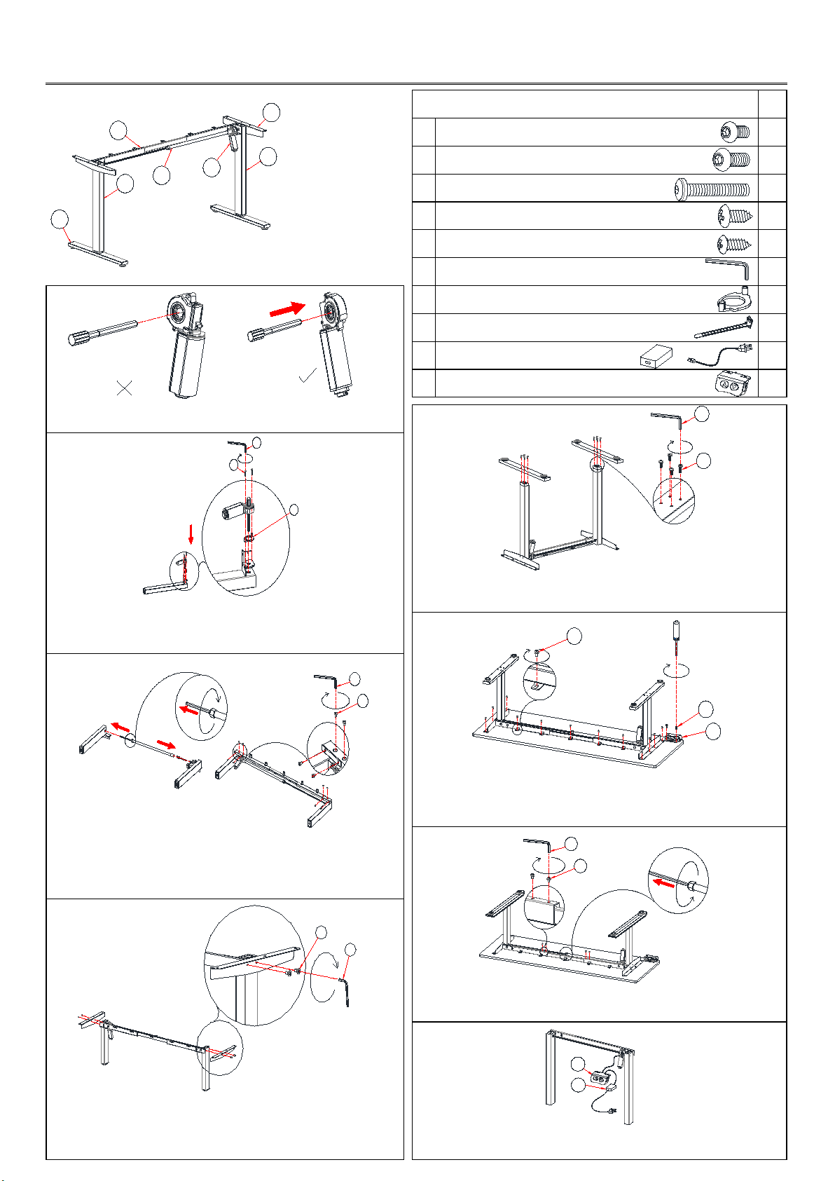
①Foot Parts Included Qty
②Right lifting leg A Screw M6x10 16
③Left lifting leg B Screw M6x16 8
④Side bracket C Screw M5x30 2
⑤Motor D Wood screw ST4.8x16 13
⑥Crossbeam E Wood screw ST4.2x16 2
⑦Hexagonal rod F Allen wrench 4mm 1
Step 1 G Motor Gasket 1
H Cable clip 5
I Power cable 1
J Handset 1
As the picture 2 show: Pass the Hexagonal rod (part 7) through the
hexagonal hole of the Motor (part 5). Step 5
Step 2
Insert the Hexagonal rod assembled in Step 1 into the hexagonal
hole of the Right lifting leg (part 2) through the Motor Gasket (part
G), and tighten it with (part C) Screw M5x30.
Attach Foot (part 1) to the Lifting leg (parts 2 and 3) using (part B)
Screw M6x16.
Step 6
Step 3
Adjust Crossbeams to the proper position to fit the desktop. Tighten
the (part D) Wood screw ST4.8x16 to lock. Attach the Handset (part J)
to the underside of the desktop using (part E) Wood screw ST4.2x16.
Insert the other side of the Hexagonal rod into the hexagonal hole
of the Left lifting leg (part 3) and Right lifting leg (part 2), and
attach the Crossbeam (part 6) to the Lifting leg (parts 2 and 3)
using (part A) Screw M6x10.
Step 7
Step 4
Tighten Crossbeams (part 6) using (part A) Screw M6x10. Adjust the
Hexagonal rod (part 7) to the proper position and tighten the plastic
screw.
Step 8
Attach the Side bracket (part 4) to the Crossbeam (part 6) using
(part A) Screw M6x10.
Connect the Motor cable (part 5) and Power cable (part I) to the
Handset (part J).
1
3
2
4
6
75
C
G
F
A
F
A
F
D
E
J
A
F
图1
图2
B
F
J
I

Specifications
Input voltage: 100-240VAC, 50/60HZ, Max3A
Output voltage: Max32VDC/Max6A
Motor: 1
Duty cycle: Max.10%
Ambiance temperature: -20℃— 50℃
Noise: ≤ 50 dB
Instructions For Use
IMPORTANT: You must reset the lifting column prior to use.
Reset Procedure:
1. Press and hold the DOWN button on the handset until the column reaches its lowest height.
2. Release the DOWN button.
3. Press and hold the DOWN button for about 5 seconds until the desk slightly rises 5mm, and stops.
4. Release the DOWN button. The desk will be ready to use.
Adjust desk height:
Press UP or DOWN button to adjust the lifting height.
NOTE
Do not attempt to open the housing of the following components
Contact with electrical voltage may cause serious injury and death by electrocution
Do not pull on the power cord to unplug the plug from the power outlet
If any issues, please contact your sales rep.
Other Ergo Furniture Indoor Furnishing manuals


Popular Indoor Furnishing manuals by other brands

RSA Lighting
RSA Lighting Microgem MLV2037 specification

JWA
JWA Yarrow 68205 Assembly instruction

Walker Edison
Walker Edison B42STC Assembly instructions

Flash Furniture
Flash Furniture SDA-AD723002-4-BK-GG Assembly instructions

DITALIA
DITALIA RC-30 Assembly manual

Bensons for Beds
Bensons for Beds STK268008 Assembly instructions


