manuals.online logo
Brands
  1. Home
  2. •
  3. Brands
  4. •
  5. Teknik
  6. •
  7. Indoor Furnishing
  8. •
  9. Teknik 5420173 User manual

Teknik 5420173 User manual

NOTE: THIS INSTRUCTION
BOOKLET CONTAINS IMPORTANT
SAFETY INFORMATION.
PLEASE READ AND KEEP FOR
FUTURE REFERENCE.
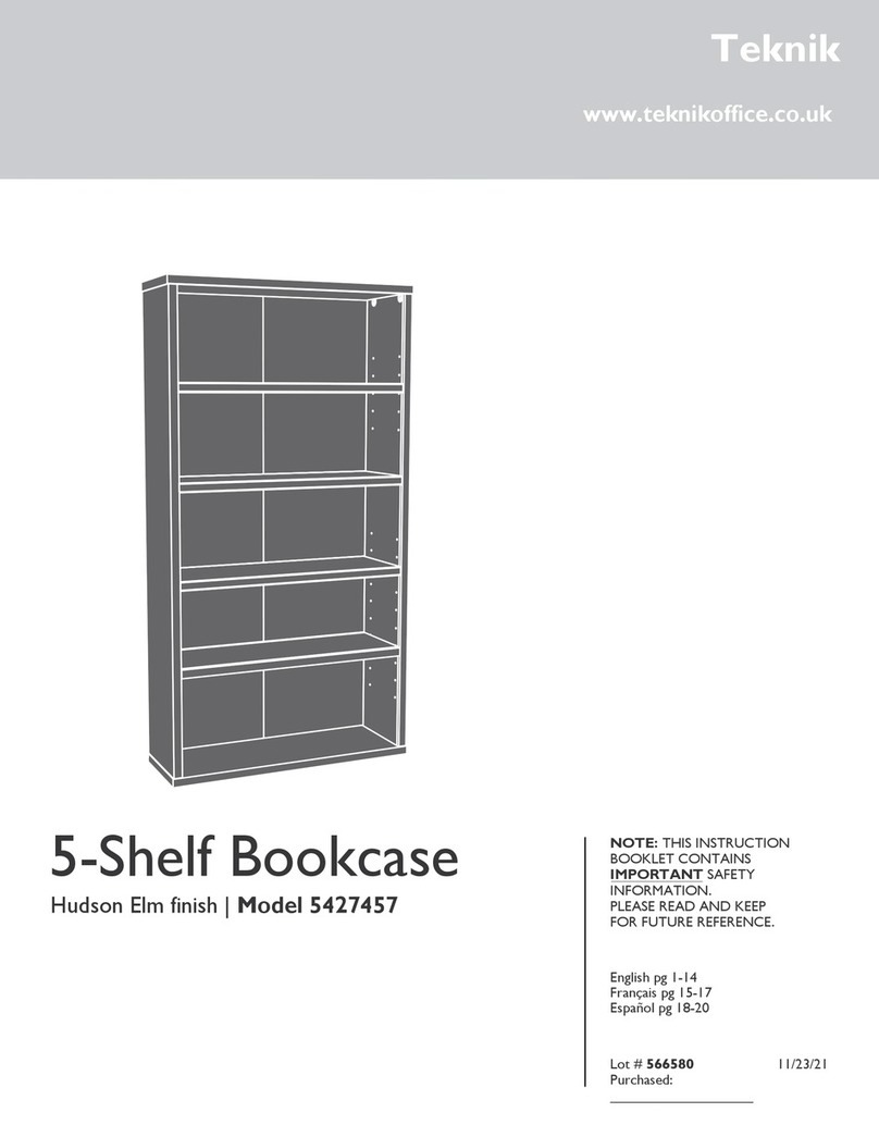
5-Shelf Bookcase
Barrister Home | Model 5420173
Great for all those
books you’ll never read.
Teknik
www.teknikoffice.co.uk
Table of Contents Assembly Tools Required
2-3
4
5-18
19
Part Identification
Hardware Identification
Assembly Steps
Safety
Hammer
Not actual size
No. 2 Phillips Screwdriver
Tip Shown Actual Size
Page 2
Part Identification
åWhile not all parts are labeled, some of the parts will have a label or an inked letter on the edge
to help distinguish similar parts from each other. Use this part identification to help identify similar parts.
A2 RIGHT END (1)
B2 LEFT END (1)
C LOWER RIGHT END (1)
D LOWER LEFT END (1)
E2 TOP (1)
F BOTTOM (1)
G2 SHELF (1)
H2 LARGE BACK (1)
I BACK (1)
J ADJUSTABLE SHELF (3)
K END MOLDING (2)
M25 TOP MOLDING (1)
M48 BASE (1)
N SHELF MOLDING (3)
O SKIRT (1)
P LOWER END MOLDING (2)
Skip the power trip.
This time.
Tape Measure
Nail Holder (provided)
Part Identification Now you know
our ABCs.
Page 3
A2
B2
C
D
E2
F
G2
H2
I
J
K
N
O
P
N
N
K
P
J
J
M48
M25
Hardware Identification
åScrews are shown actual size. You may receive extra hardware with your unit.
Page 4
HIDDEN CAM - 12
1F CAM DOWEL - 12
2F
CAM COVER - 8
13P HOLE PLUG - 3
14P METAL PIN - 12
1R
BLACK 1-1/8" PAN HEAD SCREW - 3
9S
BLACK 9/16" LARGE HEAD SCREW - 16
1S
NAIL - 55
1N
ANGLE BRACKET - 8
27G
BLACK 1-15/16" FLAT HEAD SCREW - 4
113S
FURNITURE TIPPING
RESTRAINT KIT - 1
97
Step 1
å Assemble your unit on a carpeted floor or on the empty
carton to avoid scratching your unit or the floor.
å Push twelve HIDDEN CAMS (1F) into the ENDS (A2 and B2),
LOWER ENDS (C and D), and BOTTOM (F). Then, insert the
metal end of a CAM DOWELS (2F) into the HIDDEN CAMS.
Page 5
Insert the metal end of the CAM
DOWEL into the HIDDEN CAM.
Arrow
Do not tighten the HIDDEN CAMS in this step.
A2
B2
C
D
F
Arrow
1F
2F
(12 used)
Step 2
å Open the FURNITURE TIPPING RESTRAINT KIT (97) and fasten
the SAFETY STRAP to the TOP (E2). Use the provided BLACK
9/16" LARGE HEAD SCREW.
å NOTE: Position the SAFETY STRAP exactly as shown.
Page 6
E2
Surface with holes
Long finished edge
Remember:
Righty tighty.
Lefty loosey.
BLACK 9/16" LARGE HEAD SCREW
(1 used for the SAFETY STRAP)
Safety strap
97
Step 3
Page 7
Start Tighten
Arrow
Minimum
190 degrees
Caution
Risk of damage or
injury. HIDDEN CAMS
must be completely
tightened. HIDDEN
CAMS that are not
completely tightened
may loosen, and parts
may separate. To
completely tighten:
Arrow
Maximum
210 degrees
A2
B2
E2
Notched edge
Notched edge
Surface with
HIDDEN CAMS
Surface without
HIDDEN CAMS
Surface with holes
Do not stand the unit upright without the
BACK fastened. The unit may collapse.
Caution
å Fasten the TOP (E2) to the ENDS (A2 and B2). Tighten
four HIDDEN CAMS.
Long finished edge
Step 4
å Fasten the TOP MOLDING (M25) to the TOP (E2). Use three BLACK 1-1/8" PAN
HEAD SCREWS (9S).
å NOTE: Do not overtighten the SCREWS into the TOP.
å Insert three HOLE PLUGS (14P) into the holes in the TOP MOLDING (M25).
å Slide the END MOLDINGS* (K) onto the notched edges of
the ENDS (A2 and B2).
å * U.S. Patent No. 5,499,886
Page 8
Notched edge
Notched edge
A2
B2
K
K
Slide the END MOLDINGS (K)
onto the notched edges.
The large groove is
closer to this edge.
The large groove is
closer to this edge.
Curved edge
E2
14P BLACK 1-1/8" PAN HEAD SCREW
(3 used in this step)
9S
M25
å Fasten the SHELF (G2) to the ENDS (A2 and B2). Use four
BLACK 1-15/16" FLAT HEAD SCREWS (113S).
Step 5
Page 9
A2
B2
G2
Long finished edge
BLACK 1-15/16" FLAT HEAD SCREW
(4 used in this step)
113S
Don't worry. It isn't
Rome. This can be built
in a day.
Surface with
more holes
Step 6
å Fasten the LOWER LEFT END (D) to the SHELF (G2).
Tighten two HIDDEN CAMS.
å Fasten the BOTTOM (F) to the LOWER LEFT END (D).
Tighten two HIDDEN CAMS.
Page 10
Arrow
Minimum
190 degrees
Maximum
210 degrees
Notched edge
Surface with
HIDDEN CAMS
G2
F
Surface with
HIDDEN CAMS
These holes
must be here.
D
å Fasten the LOWER RIGHT END (C) to the BOTTOM (F)
and SHELF (G2). Tighten four HIDDEN CAMS.
å Slide the LOWER END MOLDINGS (P)* onto the notched
edges of the LOWER ENDS (C and D).
å * U.S. Patent No. 5,499,886
Step 7
Page 11
Arrow
Minimum
190 degrees
Maximum
210 degrees
Notched edge
Notched edge
C
D
P
P
Slide the LOWER END
MOLDINGS (P) onto
the notched edges.
G2
F
Surface without
HIDDEN CAMS
The large groove is
closer to this edge.
The large groove is
closer to this edge.
Step 8
Page 12
å Fasten five ANGLE BRACKETS (27G) to the LOWER ENDS (C and D) and
BOTTOM (F). Use five BLACK 9/16" LARGE HEAD SCREWS (1S).
å NOTE: Be sure the ANGLE BRACKETS are even with the edges of the
LOWER ENDS and BOTTOM.
å Fasten the BASE (M48) to the LOWER ENDS (C and D) and BOTTOM (F).
Use five BLACK 9/16" LARGE HEAD SCREWS (1S).
C
D
F
27G
27G
27G
BLACK 9/16" LARGE HEAD SCREW
(10 used in this step)
1S
Finished surface
M48
Wide edge
Step 9
Page 13
å Fasten three ANGLE BRACKETS (27G) to the SHELF (G2).
Use three BLACK 9/16" LARGE HEAD SCREWS (1S).
å Fasten the SKIRT (O) to the SHELF (G2). Use three
BLACK 9/16" LARGE HEAD SCREWS (1S).
å NOTE: There are no pre-drilled holes in the SKIRT. The
SCREWS will tighten into the groove.
å Carefully turn your unit over onto its front edges.
G2
O
27G
BLACK 9/16" LARGE HEAD SCREW
(6 used in this step)
1S
T
U
R
N
O
V
E
R
O
N
L
O
N
G
E
D
G
E
T
U
R
N
O
V
E
R
O
N
L
O
N
G
E
D
G
E
Do not stand the unit upright without the
BACK fastened. The unit may collapse.
Caution
å Unfold the LARGE BACK (H2) and lay it over your unit.
å Make equal margins along all four edges of the LARGE BACK (H2). Push on opposite corners of your unit if needed to
make it "square".
å A perforation in the LARGE BACK (H2) has been provided for access to the SAFETY STRAP. Punch out the perforation
and push the SAFETY STRAP through the hole.
å Fasten the LARGE BACK (H2) to three edges of your unit using the NAILS (1N).
We have provided a Nail Holder tool to use
in this step for proper positioning of the NAILS. Please refer to the parts of the Nail Holder as the bead, oset edge, and nail
slot as shown in the diagrams below
å Diagram 1.
Place the oset edge of the Nail Holder down.
The NAILS should be 5-1/2" apart, 1-1/2" from the corners. and
be sure the NAILS are 1/2" from each fold line in the BACK. Place a NAIL (1N) into the nail slot of the Nail Holder. Tap the
NAIL through the BACK and into lower edge of the END shown. Remove the Nail Holder from the NAIL and completely tap
the NAIL in with your hammer. Repeat this to tap the remaining NAILS in the top and side edges of the BACK.
å NOTE: Do not tap nails into the bottom edge of the
LARGE BACK at this time.
Step 10
1"
1/2"
Unfinished
surface
H2
Do not fasten NAILS
along this edge until the
BACK (I) is overlapping
the LARGE BACK (H2).
NAIL
(24 used in this step)
1N
Before fastening the
BACK, punch out the
perforation and push
the SAFETY STRAP
through the hole.
Safety strap
1.
Bead
Nail slot
Nail
Holder
Oset edge
Do not stand the unit upright without the
BACK fastened. The unit may collapse.
Caution
5-1/2"
1-1/2"
Oset edge
Page 14
å Position the BACK (I) over the lower portion of your unit, making equal margins along the bottom
and side edges.
å Fasten the BACK (I) to the bottom and side edges of your unit using the NAILS (1N) using the Nail
Holder tool as shown in the previous step.
å NOTE: The BACK (I) will overlap the LARGE BACK (H2) as shown in the enlarged diagram.
å Fasten the BACK and LARGE BACK to the SHELF (G2) using the remaining NAILS (1N). by
following the enlarged diagram below.
å Diagram: Place the bead of the Nail Holder down onto the LARGE BACK (H2) and BACK (I).
Place
a NAIL into the nail slot of the Nail Holder. Tap the nail through the BACKS (H2 and I). Repeat this to
tap the remaining NAILS on the top edge of the BACK (I).
Step 11
I
Unfinished
surface
H2
I
G2
The BACK (I)
overlaps the
LARGE BACK (H2).
Bead
H2
NAIL
(31 used in this step)
1N
Page 15
G2
Step
Page 16
Step 12
å Carefully stand your unit upright in its final position against a wall.
å NOTE: Do not turn the SAFETY DRYWALL ANCHOR into a wall stud. If you prefer to fasten the SAFETY
STRAP to a wall stud, go to your local hardware store for proper hardware.
å INSTALLATION INSTRUCTIONS:
1. Insert the SAFETY DRYWALL ANCHOR through the WASHER and the end of the SAFETY STRAP.
2. Using a Phillips screwdriver or a hand drill, press the screw slightly onto the drywall just below the top surface of your
unit so the SAFETY STRAP will not be visible.
3. Apply pressure; turn the screw until a pilot hole is made and the nylon sheath slips through.
4. Turn the screw until it is flush against the wall and you feel a firm resistance.
5. Continue to turn until the screw starts spinning freely.
å NOTE: Before moving your unit to a dierent location, unscrew the SAFETY DRYWALL ANCHOR from your wall. The
nylon sheath will remain behind your wall.
Pro Tip: Lift with your
legs. And, you know,
your arms.
Safety
drywall
anchor
Safety strap
Washer
97
å Slide and center a SHELF MOLDING* (N) onto the notched
edge of one of the ADJUSTABLE SHELVES (J).
å Repeat this step for the other ADJUSTABLE SHELVES (J).
å * U.S. Patent No. 5,499,886
å Insert the METAL PINS (1R) into the hole locations of your
choice in the ENDS (A2 and B2) and LOWER ENDS (C and D).
Set the ADJUSTABLE SHELVES (J) onto the METAL PINS.
Step 13
Page 17
J
Slide the SHELF
MOLDING (N) onto
the notched edge.
N
These surfaces
should be even.
1R
(12 used)
J
J
J
A2
C
D
B2
The large groove is
closer to this edge.
Notched edge
Step 14
å Using your hammer, gently tap a CAM COVER (13P) onto each visible HIDDEN CAM.
å NOTE: Please read the back pages of the instruction booklet for important safety information.
å This completes assembly. Clean with a damp cloth. Wipe dry.
Page 18
To cover HIDDEN CAMS
(8 used)
13P
No load
40 lbs.
50 lbs.
30 lbs.
30 lbs.
30 lbs.
Page 19
WARNING
Please use your furniture correctly and safely. Improper use can cause safety hazards,
or damage to your furniture or household items. Carefully read the following chart.
Look out for: What can happen: How to avoid the problem:
• Overloaded shelves.
• Improper loading can cause the
product to be top-heavy.
• Risk of injury.
• Top-heavy furniture can tip over.
• Overloaded shelves can break.
• Never exceed the weight limits shown in
the instructions.
• Work from bottom to top when loading
shelves. Place the heavier items on the
lower shelves.
• Improperly moving furniture that is not
designed and equipped with casters. • Furniture can tip over or break if
improperly moved.
• Physical injury. Furniture can be very
heavy.
• Unload shelves from top to bottom before
moving the furniture.
• Do not push furniture, especially on a
carpeted floor. Have a friend help you lift
the item and set it in place.
• This unit must be positioned against a
wall.
• Children climbing on the shelves can
cause the product to tip. • Risk of injury or death. • Do not allow children to climb on the
shelves. Avoid placing items like toys or
candy on upper shelves.
• Use the supplied safety strap for added
stability.
• Placing TVs on furniture items that are
not designed to support a television is
hazardous.
• Risk of injury or death. TVs can be very
heavy. Plus the weight and location of the
picture tube tends to make TVs unbalanced
and prone to tipping forward.
• This product is not designed to support a
television.

Other Teknik Indoor Furnishing manuals
Teknik Clifton Place 5421113 User manual

Teknik

Teknik Clifton Place 5421113 User manual

Teknik Barrister Home 5418705 User manual

Teknik

Teknik Barrister Home 5418705 User manual

Teknik Scribed Oak Desk 5414836 User manual

Teknik

Teknik Scribed Oak Desk 5414836 User manual

Teknik 5423505 User manual

Teknik

Teknik 5423505 User manual

Teknik 5426463 User manual

Teknik

Teknik 5426463 User manual

Teknik Hudson Chunky Desk 5425833 User manual

Teknik

Teknik Hudson Chunky Desk 5425833 User manual

Teknik City Centre 5427120 User manual

Teknik

Teknik City Centre 5427120 User manual

Teknik Barrister Home User manual

Teknik

Teknik Barrister Home User manual

Teknik Craft 5421407 User manual

Teknik

Teknik Craft 5421407 User manual

Teknik Executive Trestle Desk 5424128 User manual

Teknik

Teknik Executive Trestle Desk 5424128 User manual

Teknik Canyon Lane 5425306 User manual

Teknik

Teknik Canyon Lane 5425306 User manual

Teknik 5431262 User manual

Teknik

Teknik 5431262 User manual

Teknik Hampstead Park 5423704 User manual

Teknik

Teknik Hampstead Park 5423704 User manual

Teknik Barrister Home L-Shaped Desk 5418270 User manual

Teknik

Teknik Barrister Home L-Shaped Desk 5418270 User manual

Teknik Barrister Home 5417772 User manual

Teknik

Teknik Barrister Home 5417772 User manual

Teknik Canyon Lane 5425302 User manual

Teknik

Teknik Canyon Lane 5425302 User manual

Teknik Boulevard Cafe 5420650 User manual
Teknik

Teknik Boulevard Cafe 5420650 User manual

Teknik Clifton Place 5421116 User manual

Teknik

Teknik Clifton Place 5421116 User manual

Teknik 5424943 User manual

Teknik

Teknik 5424943 User manual

Teknik Hampstead 5426504 User manual

Teknik

Teknik Hampstead 5426504 User manual

Teknik 5427134 User manual

Teknik

Teknik 5427134 User manual

Teknik Elstree 5426910 User manual

Teknik

Teknik Elstree 5426910 User manual

Teknik Barrister Home 4 Drawer Chest User manual

Teknik

Teknik Barrister Home 4 Drawer Chest User manual

Teknik Lateral Filer 5421114 User manual
Teknik

Teknik Lateral Filer 5421114 User manual

Popular Indoor Furnishing manuals by other brands

Maidesite Standing Desk Assembly instructions

Maidesite

Maidesite Standing Desk Assembly instructions

SOS BM Seating System user manual

SOS

SOS BM Seating System user manual

Pipe Decor 365 ET30 quick start guide

Pipe Decor

Pipe Decor 365 ET30 quick start guide

Costway KC53544 user manual

Costway

Costway KC53544 user manual

Oxford Garden Hampton Counter Stool HACST Assembly instructions

Oxford Garden

Oxford Garden Hampton Counter Stool HACST Assembly instructions

Livarno Living 114813 Assembly instruction

Livarno Living

Livarno Living 114813 Assembly instruction

Next MALVERN 284262 Assembly instructions

Next

Next MALVERN 284262 Assembly instructions

Amart Furniture 56928 Assembly instruction

Amart Furniture

Amart Furniture 56928 Assembly instruction

Gordon Ellis & CO LANgHAM K100 manual

Gordon Ellis & CO

Gordon Ellis & CO LANgHAM K100 manual

Oeseder Möbelindustrie 992 557 Assembly instructions

Oeseder Möbelindustrie

Oeseder Möbelindustrie 992 557 Assembly instructions

HULALA HOME HCHS010 quick start guide

HULALA HOME

HULALA HOME HCHS010 quick start guide

Royalcraft Wentworth WENFIXCOMP-WS Assembly instructions

Royalcraft

Royalcraft Wentworth WENFIXCOMP-WS Assembly instructions

Next 645958 Assembly instructions

Next

Next 645958 Assembly instructions

Loll Designs SALMELA LUSSI ASSEMBLY INSTRUCTIONS & PRODUCT INFO

Loll Designs

Loll Designs SALMELA LUSSI ASSEMBLY INSTRUCTIONS & PRODUCT INFO

FURNITUREBOX MOON CHAIR Assembly guide

FURNITUREBOX

FURNITUREBOX MOON CHAIR Assembly guide

Permobil ROHO SOFFLEX 2 Operation manual

Permobil

Permobil ROHO SOFFLEX 2 Operation manual

Tech Craft BG4020 Assembly instruction

Tech Craft

Tech Craft BG4020 Assembly instruction

PURE comfort 8502AB manual

PURE

PURE comfort 8502AB manual

manuals.online logo
manuals.online logoBrands
  • About & Mission
  • Contact us
  • Privacy Policy
  • Terms and Conditions

Copyright 2025 Manuals.Online. All Rights Reserved.