Ergo In Demand PPD Series User manual

Plasma Presenters Dual Display
V
ideo Conferencing Cart (PPD-Series)
BEFORE YOU BEGIN
•CAUTION: To prevent damage to the cart, which could affect or void the Factory warranty, thoroughly
study all instructions and illustrations before you begin to install or operate the unit. Pay particular atten-
tion to the “Important Precautions” on Page 1.
• The maximum weight to be installed on the PPD is 200 pounds (90.72 Kg).
• If you have any questions about this assembly, contact Ergo In Demand at 1-800-888-6024 or 541-779-3763
I N S T R U C T I O N M A N U A L
The PPD is a highly functional video conferencing solu-
tion. The cart provides agile mobility for two Large Flat
Panel Displays, side-by-side, with a combined weight of
up to 200 pounds. Optional equipment shelves and video
conferencing accessory shelves can be easily added for
a complete system.
Using the exclusive Q-latch™ Mounting System for
easy installation, the cart provides stable mounting, quick
release and optional security. Additionally, its streamline
shape eliminates trip hazards and allows the display to
roll smoothly up to a conference table
Large swivel casters with lock brakes, pitch adjustment,
and cable management make the cart user friendly.
1-800-888-6024 541-779-3763 FAX 541-779-0829
4900 Industry Drive
Central Point, Oregon 97502 USA
PART NO. 8809-000004 (Rev. B)
01-05
Ergo In Demand, Inc.

Instruction Manual Dual Display Video Conferencing Cart
1
IMPORTANT WARNINGS and CAUTIONS!
WARNING: A WARNING alerts you to the possibility of serious injury or death if you do not follow the instructions.
CAUTION: ACAUTION alerts you to the possibility of damage or destruction of equipment if you do not follow the corre-
sponding instructions.
• WARNING: Do not attempt to hang the Plasma Display Panel onto the cart alone. Always use two people to hang the
display.
• WARNING: Always park the cart on a level surface. The locking wheels of the cart are not designed to hold the cart on
an inclined surface.
• WARNING: Do not use the cart to transport your Plasma Display Panels on ramps or steep angles. The cart is
designed to move on smooth, flat surfaces.
•CAUTION: Inspect the unit for shipping damage.
•CAUTION: Do not use cleanser or harsh cleaning agents on acrylic shelves.
TOOLS REQUIRED FOR INSTALLATION
• 7/16” and 3/4” wrench
• Allen wrenches
• Socket set with extension
NOTE: Other tools may be required depending on the
method of installation.
CONTENTS
INSPECT PARTS BEFORE ASSEMBLY ......... 2
Inspect The Cart ................................................. 2
OPTIONAL ACCESSORIES .............................. 4
ASSEMBLE CART ............................................. 4
MOUNT FLAT PANEL DISPLAYS
ON CART............................................................. 6

2
Instruction Manual Dual Display Video Conferencing Cart
INSPECT PARTS BEFORE ASSEMBLY
Inspect The Cart
1. Carefully inspect the cart for shipping damage. If any
damage is apparent, call your carrier claims agent and do
not continue with the assembly procedure until the carrier
has reviewed the damage.
NOTE: Read all assembly instructions before assembly.
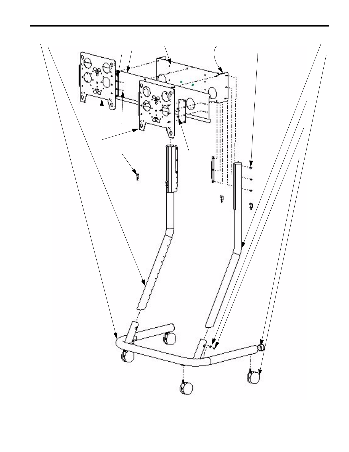
2. Carefully inspect the Plasma Presenters Dual Cart (PPD)
components (See Table 1 and Figure 1) and Accessories
(see Table 2 and Figure 2) for damage
Table 1: Parts
Item# Description Quantity
10 BASE with corner supports 1
20 LEG, Right 1
30 LEG, Left 1
40 HEAD, Mounting 1
50 SPREADER, Head Tilt (viewed from inside) 2
60 BRACKET, Dual Screen Mounting 1
70 FACEPLATE, Sides 4
80 SCREW, Cap, Button head, 5/16-18X3/4 6
90 CASTERS (2 Locking) 4
100 WRENCH, Allen, 3/16” (Not Shown) 1
110 WASHER, 1/4” 2
120 SCREW, Phillips Pan, 10-24X1/2” 2
130 SCREW, Cap, Button head, 1/4X20X5/8” 28
140 PLUG, Cap (2 hard plastic, 2 slip on vinyl) 4
150 WRENCH, Allen, 5/32” (Not Shown) 1
160 PLATE, Face 2
170 LATCH (Not Shown) 2
180 NUT, Lock, 10-24 (Not Shown) 2
190 WASHER, Nylon (Not Shown) 2
200 PAC-140 (Q-clamps) 4
210 SCREW, Cap, Button head, 1/4X20X7/8” 4
Instruction Manual Dual Display Video Conferencing Cart
3
10 30 40
60
70 80
110
50
120
130
140
200
20
90
120
160
210
Figure 1. Parts
4
Instruction Manual Dual Display Video Conferencing Cart
OPTIONAL ACCESSORIES
1. Acrylic Shelf
2. Video Conferencing Shelf
ASSEMBLE CART
Numbers in ( ) refer to parts shown in Figure 1.
Assemble cart as follows:
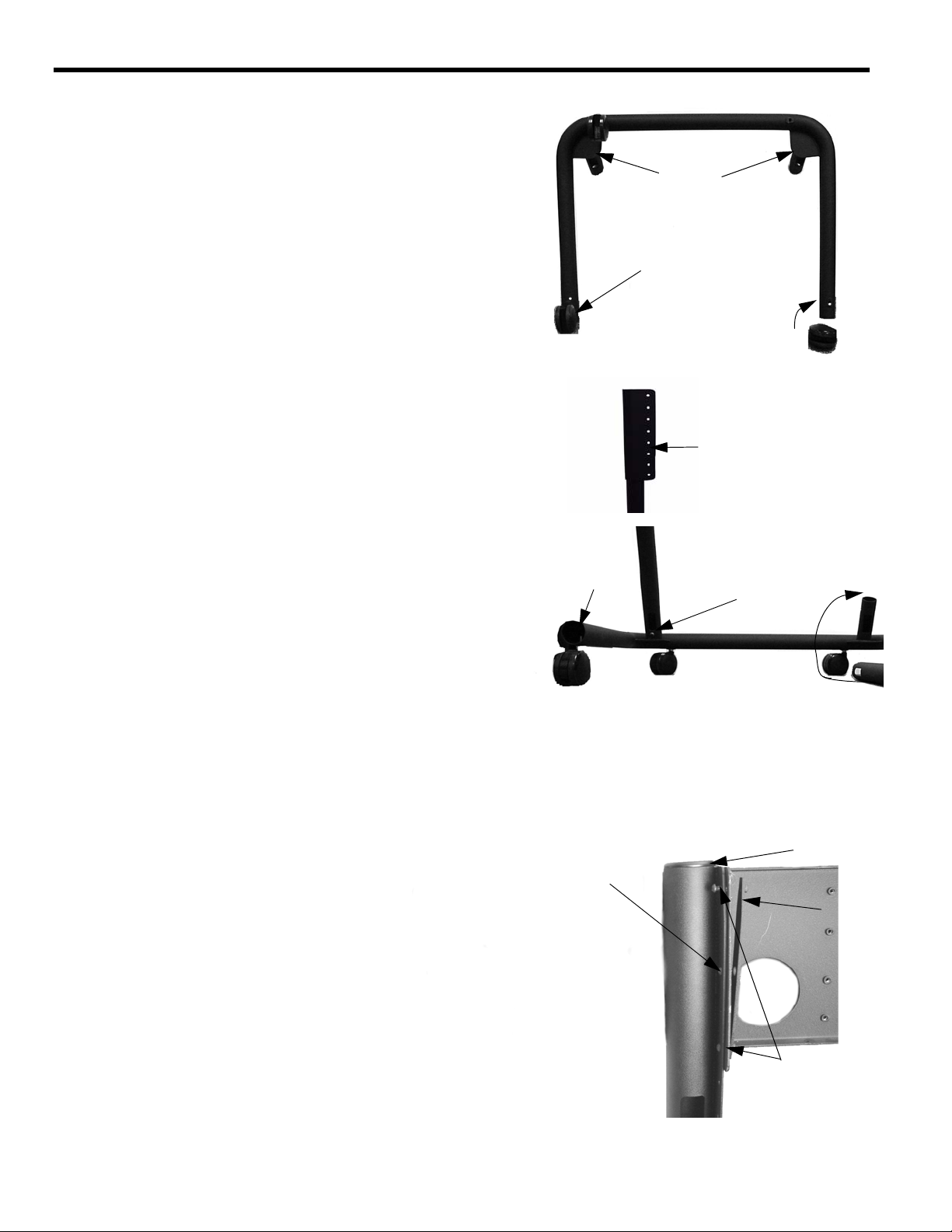
1. Place base (10) upside down and thread two locking
casters and two regular casters (90) into base
(see Figure 3).
2. Place base upright on casters, Install right leg (20) and
left leg (30), making sure the mounting tabs face inward
(see Figure 4). Secure legs using two washers (110) and
two 1/4-20X1/2” screws (120).
3. Install vinyl cap plugs with star cut in base (140) (see Fig-
ure 4) and on top of each leg (see Figure 5).
4. Using a 1/4-20X5/8” button head cap screw (130), one on
each side, secure the mounting head (40) to the top of
the legs of the cart (see Figure 5).
5. Using four 1/4-20X5/8” button head cap screws (130)
(two per side) secure two tilt head spreaders (50), one
per side (see Figure 5).
Locking Casters
Casters
Figure 3. Install Casters
Facing in
Figure 4. Install Legs
Vinyl Cap Plug Posts may need to be
lifted slightly to
insert fasteners
with star cut
Install this 1/4-20 screw securing
mounting head on each side first
1/4-20 Screws
Securing
Tilt Plate
Tilt Plate
Cap Plug
(threads into mounting head)
Figure 5. Mounting Head

Instruction Manual Dual Display Video Conferencing Cart
5
6. Adjust tilt head to desired tilt by slightly loosening
four 1/4-20X5/8” button head cap screws (130) securing
tilt head spreaders (50), adjust tilt head to desired angle
(angle 0 - 7 1/2º), and tighten four 1/4-20X5/8” button
head cap screws (see Figure 6).
7. Using six 5/16-18X3/4” screws (80), secure the dual
screen mounting bracket (60) to the mounting head (40)
(see Figure 7).
Figure 7. Dual Screen Mounting Bracket to Mounting Head
5/16-18 Screws
Mounting Head Dual Screen Mounting Bracke
t
Tilt Head
Loosen Screws
Loosen Screws
Tilt Head Spreader
0 to 7.5 Degrees
Figure 6. Adjust Tilt

6
Instruction Manual Dual Display Video Conferencing Cart
MOUNT PLASMA DISPLAYS ON CART
1. Measure the distance from the center of your display to
its outermost edge.
NOTE: Make sure to leave some space between dis-
plays when mounted.
2. Using the measurement found in Step 3 and the face-
plate (160) as a template, measure from the center of the
dual screen mounting bracket (60) to find the correct
mounting holes for your application (see Figure 8).
3. Secure each face plate (160) using four 1/4-20X5/8”
screws (130) (see Figure 9).
4. Secure a latch (170) to each face plate (160) using a
10-24X1/2” screw (120), 10-24 Nylock nut (180) and
Nylon washer (190) (see Figure 10). Tighten Nylock nut
enough to allow latch to move, but remain in place when
set.
5. Install PSB brackets (included separately) on Large Flat
Panel Displays according to instructions supplied with
brackets.
WARNING: Do not attempt to hang the plasma display onto
the cart with one person.
6. With the cart rolled up against a stable vertical surface,
make sure the casters are locked.
7. Make sure the latches are positioned (lowered) so they
will not obstruct display installation (see Figure 11).
8. With one person supporting each side of the display and
another person stabilizing the cart, align the four Q-but-
tons with the four teardop slots.
9. Secure the display by completely engaging the latch.
10. Lock the display in place by installing two Q-clamps (200)
on each side of the bottom of face plate (160) as shown
in Figure 12.
11. Repeat steps 2 through 6 for second display.
Figure 8. Face Plate and Dual Mounting Head Measurements

Instruction Manual Dual Display Video Conferencing Cart
7
Figure 12. Install Q-Lock
Face Plate
Q-latch
Q-lock
1/4-20X7/8”
Screw
Q-clamp
Q-latch
Figure 11. Lower/Raise Latch
Latch
Figure 10. Install Latch
10-24 Nut
Latch
N
ylon washer between latch and plate
10-24x1/2” Screw
Figure 9. Dual Mounting Head with Face Plates Attached
Table of contents
Popular Outdoor Cart manuals by other brands

Expondo
Expondo Royal Catering RCZT-01W user manual

Copernicus
Copernicus BTHC2 Assembly guide

Ameriwood HOME
Ameriwood HOME 3848015COM Instruction booklet

Sport-thieme
Sport-thieme 126 4917 Operating & assembly instructions

Granite
Granite 67243-75 instruction manual

Premier Mounts
Premier Mounts LFC-L installation guide


