Ergo EBDSK4 User manual

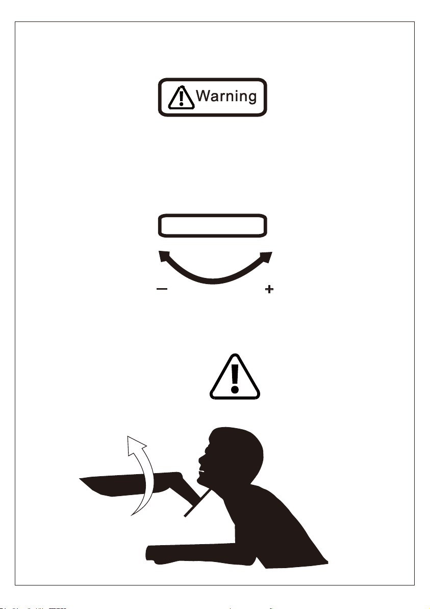
Warning!
Do not adjust tension without monitor.
1. Ensure monitor has been attached to the mount.
2. Read your monitor box or manual to find out monitor net weight.
3. Ensure the net weight of monitor (including accessories) is within
17.6 Ibs (8 kg).
Clockwise to reduce
tension(carry less weight)
Counter-clockwise to increase
tension(carry more weight)
TENSION ADJUSTMENT SHOULD BE DONE ONLY
AFTER MOUNT INSTALLATION
Adjustment Sign

01
IMPORTANT SAFETY INFORMATION
Check the VESA Pattern of Monitor Before the Installation
MAX: 100mm/4in.
MAX: 100mm/4in.
100 mm ≈ 4 in.
75 mm ≈ 3 in.
• Please read through these instructions completely before attempting
installation. If you do not understand the instructions or have any concerns or
• Check package contents against Supplied Parts and Hardware List to assure
that all components were received undamaged. Do not use damaged or defective
parts. If you require replacement parts, contact customer service at
• Not all parts and hardware included will be used.
• This product contains a high pressure gas spring, fire and percussion
prohibited. Also it is strictly prohibited to dismantle without professionals. Please
return to the manufacturer or hand over to professional agencies if the product is
abandoned.
• Do not use this product for any purpose or in any configuration not explicitly
specified in this instruction. We hereby disclaim any liability for injury or damage
arising from incorrect assembly, incorrect mounting, or incorrect use of this
product.
Minimum VESA Pattern: 3 in./75mm(W) x 3 in./75mm(H)
If your monitor VESA is greater than 100 x 100 mm/4 x 4 in. or less
than VESA 75 x 75 mm/ 3 x 3 in., this mount is NOT compatible.
If this mount is NOT compatible, please contact customer service at
[email protected] to find a compatible mount.
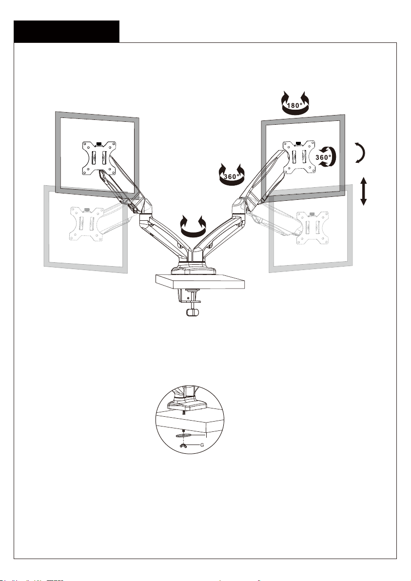
Product Features
02
270°
C-Clamp Mounting
Grommet Mounting
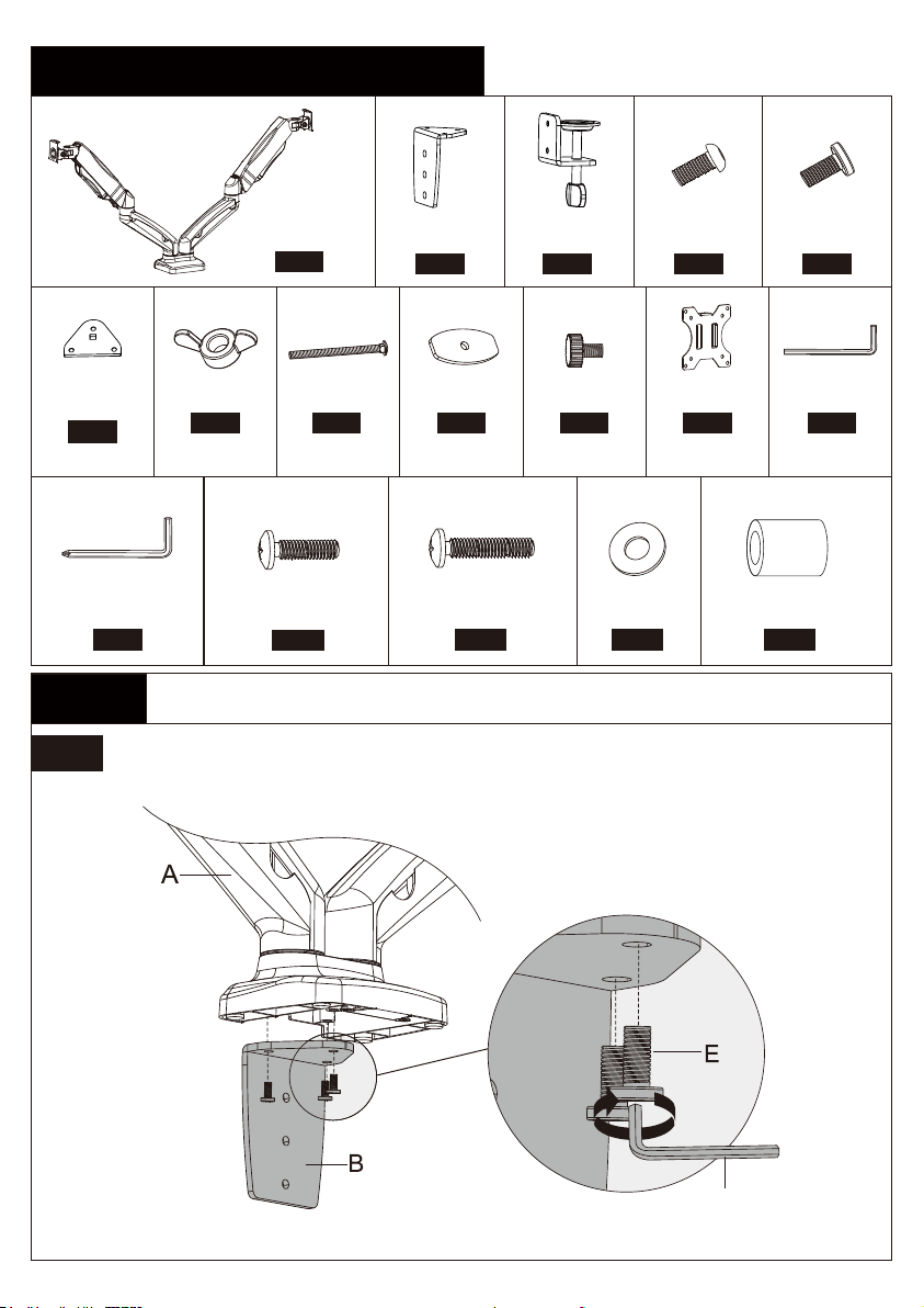
Supplied Parts and Hardware List
Ax1
Arm Assembly
Cx1
Desk Clamp
Gx1
Butterfly Nut
Hx1
Bolt
Ix1
Grommet
Plate
Lx1
5/32in.(4mm)
Allen Key
Mx1
13/64in.(5mm)
Allen Key
Step 1A For Clamp Mounting
1A-1 Connect Connecting Plate [B] to Arm Assembly [A]
Ex3
M6x12mm
Bolt
Dx2
M6x10mm
Bolt
Fx1
Bottom
Plate
03
Bx1
Connecting
Plate
Jx2
Bolt
Kx2
Monitor Plate
L
M4x12mm (x8)
M-A
Bolt
M4x30mm (x8)
M-B
Bolt
D4 (x8)
M-C
Washer
L13mm (x8)
M-D
Spacer
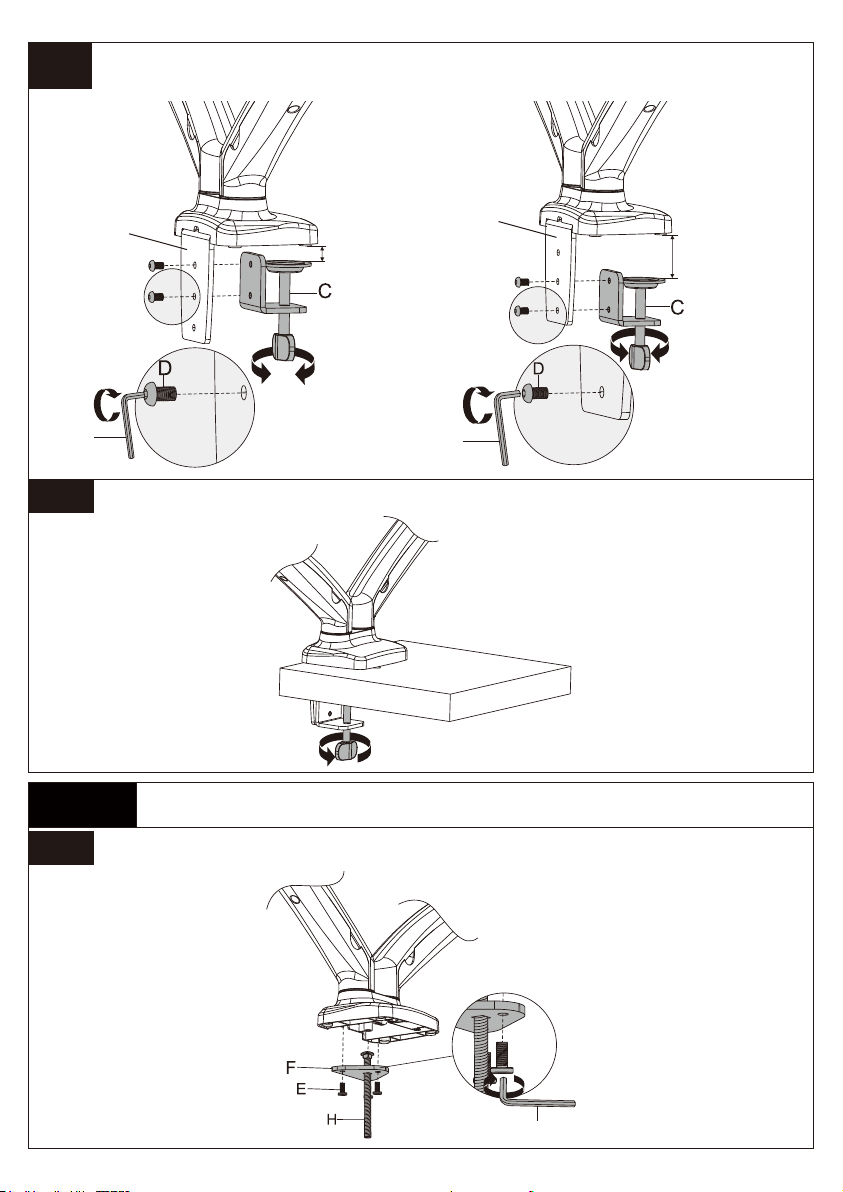
1A-2 Secure Desk Clamp [C] to Connecting Plate [B] According to the
Thickness of the Desktop
1A-3 Secure the Mount to Desktop
1B-1 Secure Bottom Plate [F] and Bolt [H] to Arm Assembly [A]
Step 1B For Grommet Mounting
04
LL
or
L
10-50mm
(0.4in.-2in.)
50-83mm
(2in.-3.3in.)
BB

05
1B-2 Secure the Mount Assembly to the Desktop
0.4-3.3 in.
(10-83 mm)
Bolt length: Verify adequate thread engagement with bolts or bolts/spacers combination. We
recommend thread engagement by at least 5 turns.
-Too short will not hold the monitor.
-Too long will damage the monitor.
M6M4
Only one bolt size fits your monitor.
Select Monitor Bolts
Attach the Monitor Plate [K] to the Monitor
Step 2
M-A
M-C
FLAT BACK MONITOR
(UNIVERSAL MONITOR PLATE)
K
M-B
M-C
ROUND BACK MONITOR
(UNIVERSAL MONITOR PLATE)
K
Too Short Too Long Correct Correct
M-D
06
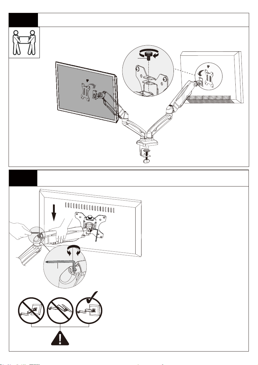
Step 4 Adjust the Gas Spring Tension
Step 3 Secure the Monitors to Arm Assembly
The tension is preset at 4-5kg.
After hanging the monitor to the
mount, please release the monitor
slowly to prevent it from falling
suddenly
J
Be sure to keep the arm in
horizontal position during
adjustment. Or else, it would be
difficult to adjust the mount or
damage the mount.
1. If the monitor can stay at the desired height by
itself, no adjustment needed.
2. If the monitor rises up, press the arm to keep it in
horizontal position and then use the 13/64in.(5mm)
Alley key [M] to turn the bolt clockwise(“-” direction)
to reduce tension of the arm only until the monitor
can stay at the desired height by itself.
3. If the monitor falls down, lift the arm to keep it in
horizontal position and then use the 13/64in.(5mm)
Alley key [M] to turn the bolt counter-clockwise(“+”
direction) to increase tension of the arm only until the
monitor can stay at the desired height by itself.
M

07
Step 6 Adjustments
“+” Clockwise: Tighten
“-” Counter-clockwise: Loosen
Situation 1: If the monitor can stay at the desired tilt angle by itself,
no adjustment needed.
Situation 2: If the monitor can not stay at the desired tilt angle by
itself, turn the bolt clockwise or counter-clockwise as shown until
the monitor can stay at the desired tilt angle by itself.
Tilt Adjustment L
Step 5 Rotation Restriction
Non-proper usage directions Proper usage directions
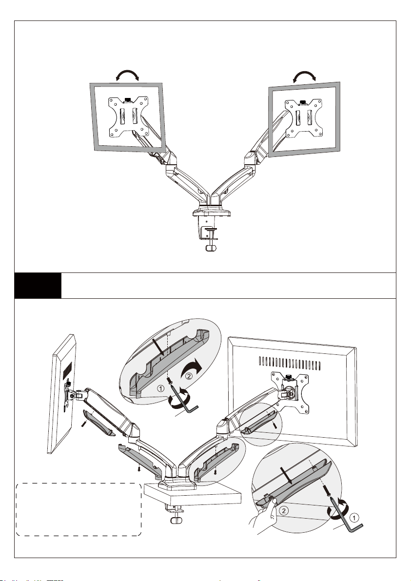
Step 7 Route the Cables Along the Arm Assembly [A]
Step 7-1 Detach the cable covers from the arm assembly [A]
Note: Loosen the preassembled
bolts from the covers, then pinch
the both sides of the bottom end
of the cable covers to make
them detach from the arm
08
Level and Rotation Adjustments
If needed, the TV can be
levelled and rotated 360
degree
M
M
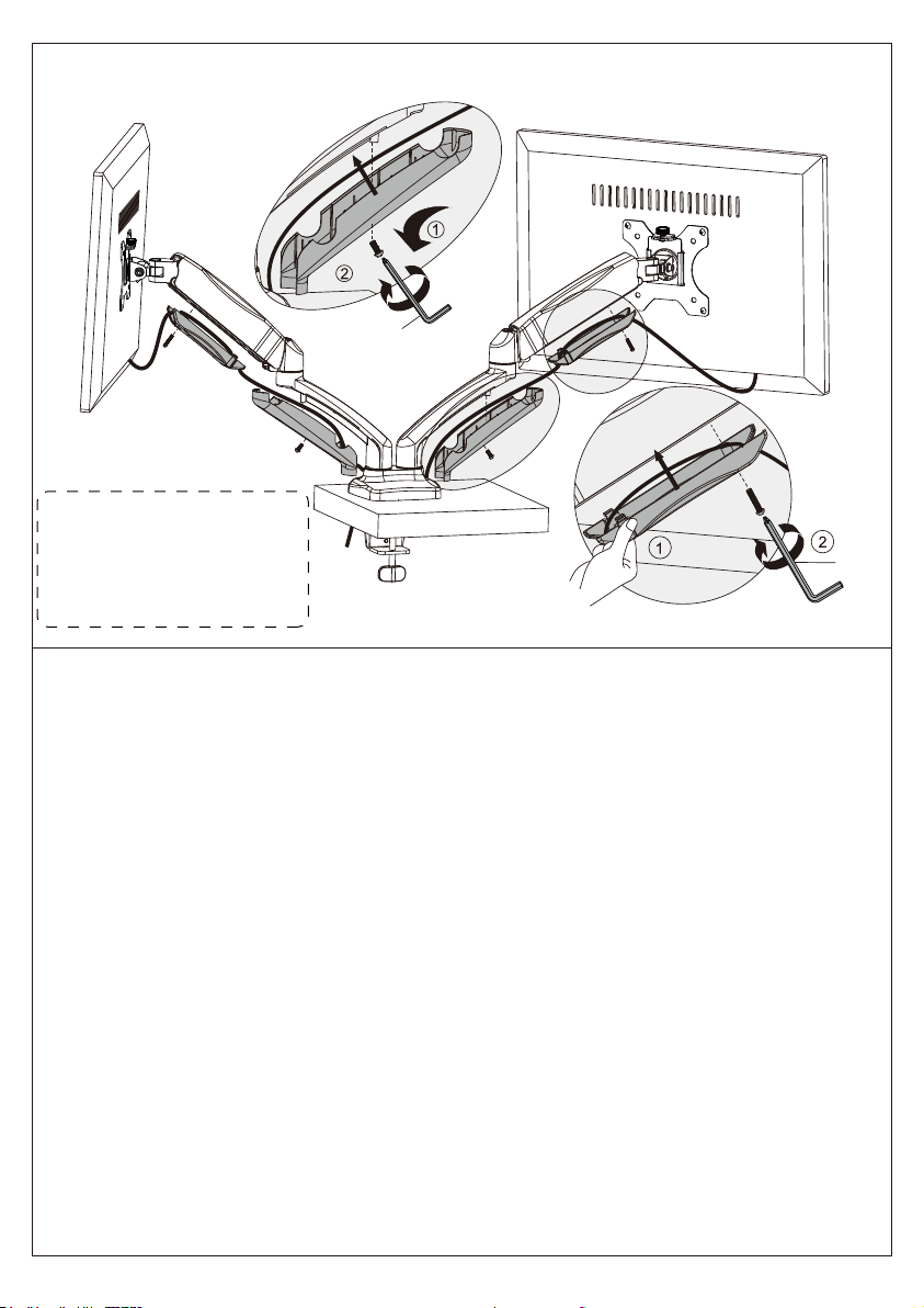
Step 7-2 Route the cables along the arm assembly and secure the cable covers
to the arm assembly [A]
09
Note: Pinch the both side of
the bottom end of the cable
covers to make them attach to
the arm, then fasten the bolts
to secure the covers to the
arm.
MM
M

Table of contents
Other Ergo TV Mount manuals


