Ergo INNOVATE EI6171 User manual

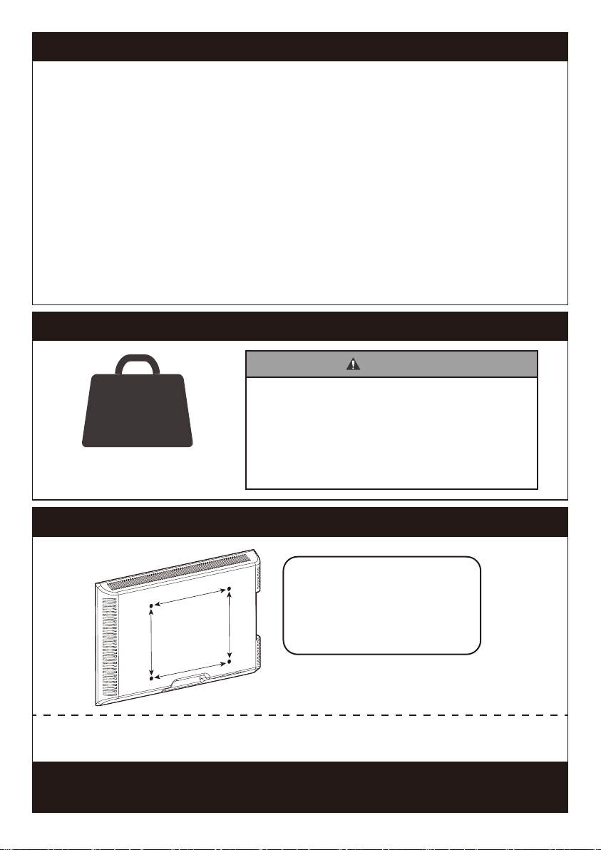
Weight Restrictions
DO NOT exceed the maximum weight indicated.
This mounting system is intended for use only
with the maximum weights indicated. Use within
products heavier than the maximum weights
indicated may result in failure of the mount and
its accessories, causing possible
damage and or injury.
WARNING
If your TV weighs more, this
mount is NOT compatible.
132 lbs.
(60.0 kg)
V1.0
IMPORTANT SAFETY INFORMATION
Please carefully read all instructions before attempting installation. If you do
not understand the instructions or have any concerns or questions, please
CAUTION: Avoid potential personal injuries and property damage!
• Do not use this product for any purpose that is not explicitly specified in this
manual. Do not exceed weight capacity. We are not liable for damage or injury
caused by improper mounting, incorrect assembly or inappropriate use.
• This product is designed for use in wood stud, solid concrete, concrete
block and brick walls - DO NOT install into drywall alone.
• The wall must be capable of supporting five times the weight of the TV and
mount combined.
Check the VESA Pattern of TV before the Installation
If your TV VESA is greater than 400x400 mm/16x16in. or less than
VESA 100x100mm/4x4 in., this mount is NOT compatible.
If this mount is NOT compatible, please contact customer service at
[email protected] to find a compatible mount.
MAX: 600mm/24 in.
MAX: 400mm/16 in.
Minimum VESA pattern:
100mm/4 in.(W)x100mm/4 in.(H)
200 mm ≈ 7 7/8 in.
400 mm ≈ 15 3/4 in.
100 mm ≈ 4 in.
300 mm ≈ 11 3/4 in.
600 mm ≈ 23 6/10 in.
01
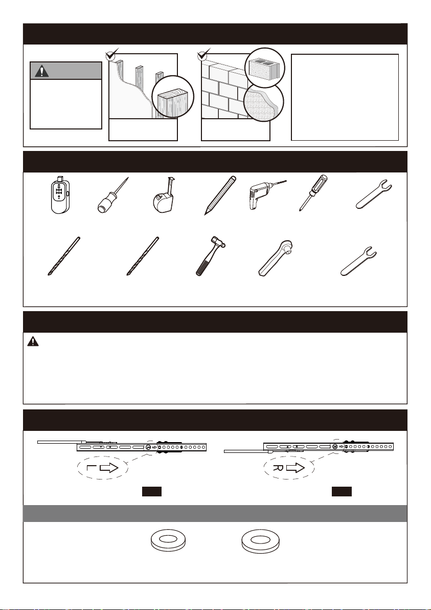
Left TV Bracket x1
03
M4/M5
[B1] x4
M6/M8
[B2] x4
Tools Needed (Not lncluded)
Supplied Parts and Hardware
Supplied Parts and Hardware for Step 1
Warning: This product contains small items that could be a choking hazard if swallowed.
Before starting assembly, verify all parts are included and undamaged. Do not use
damaged or defective parts. lf you require replacement parts, please contact our
• Please note: Not all hardware included in this package will be used.
Stud Finder Tape Measure Pencil Drill
5/32 in. (4mm)
Wood Drill
3/8 in. (10mm)
Wood Drill
3/8in. (10mm)
Socket Wrench
Phillips
Screwdriver
Hammer 5/16 in. (8mm)
Wrench
Awl
x1
04
Right TV Bracket
[B]
Washers
Solid Concrete
or Concrete Block
CAUTION
DO NOT
install into
drywall alone Wood Studs
(with Drywall)
Verify Your Wall Construction
If you are are not sure
the wall construction,
please contact our
product support line at
ssupport@ergo-innovat
e.com.
3/8in.(10mm)
Wrench
02
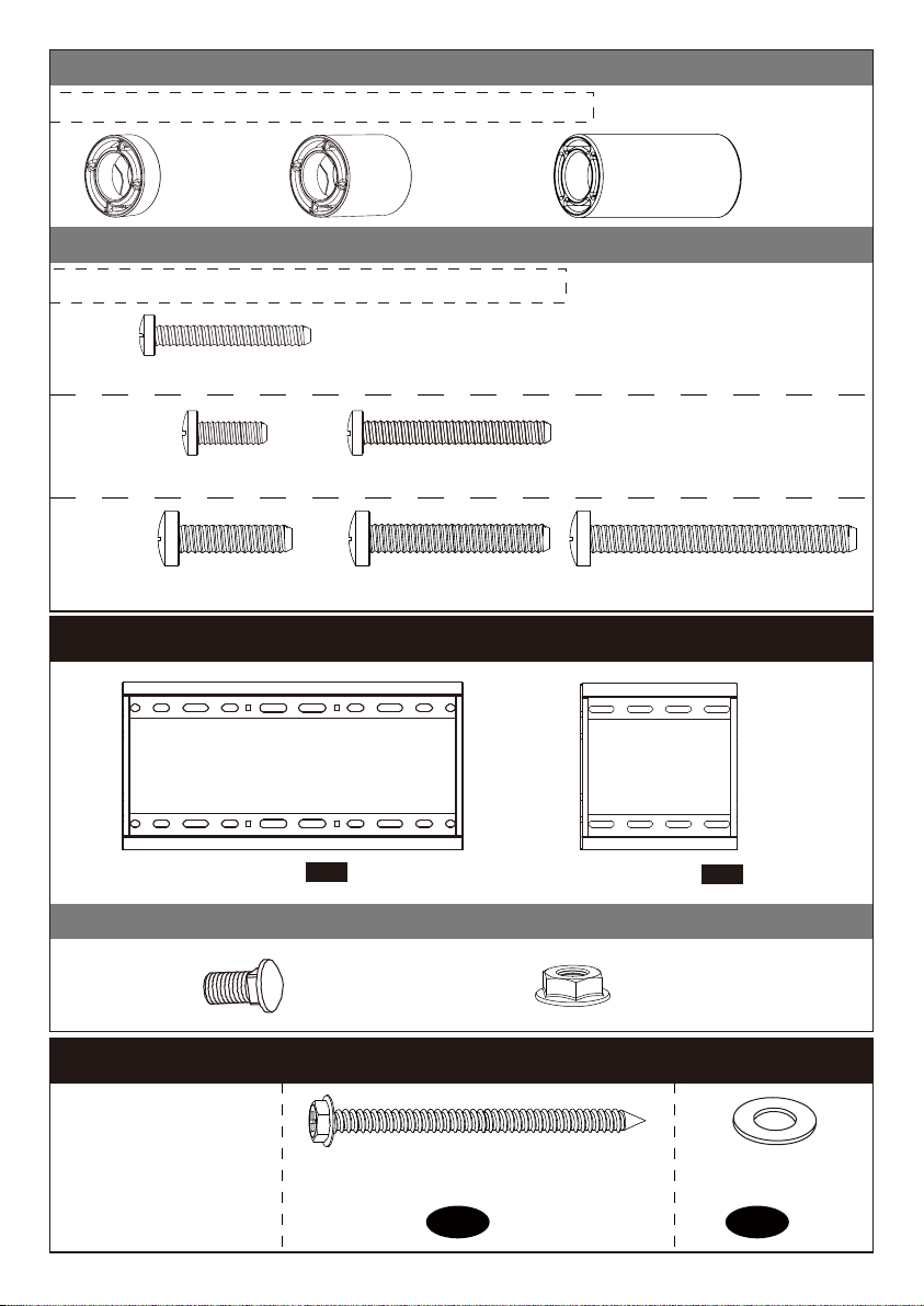
M4 M4 x 30mm
[D1]x4
M8
M8 x 25mm
[D4] x4
M8 x 35mm
[D5] x4
M8 x 50mm
[D6] x4
M6
M6 x 15mm
[D2] x4
M6 x 35mm
[D3] x4
2.5mm
[C1] x8
10mm
[C2] x4
22mm
[C3] x4
Note: The spacers are shown in accordance with the actual size.
Note: The bolts are shown in accordance with the actual size.
[C] Spacers
[If necessary]
[D] TV Bolts
Wall Plate Extender 02 x1
Wall Plate 01 x1
M6 Nut
[E2] x2
Bolt
M6X12mm
[E1] x2
[E]
Supplied Parts and Hardware for Step 2
Washer
φ6.5Xφ18X1.8mm
x4
A2
Lag Screw
ST6.3X60mm
x4
A1
Note: The lag screw is
shown in accordance
with the actual size
Supplied Parts and Hardware for Step 3
03

x1
05Level
Step 1 Secure the TV Brackets to TV
Bolt length: Verify adequate thread engagement with bolts or bolts/spacers combination.
We recommend thread engagement by at least 5 turns.
-Too short will not hold the TV.
-Too long will damage the TV.
Note: If necessary, the spacers can be used in multi-layer. If the installation
fails after trying various methods, please contact customer service at
Too Short
CorrectCorrect
Too Long
CAUTION: Ensure the TV
brackets [03] and [04] are
EQUALLY CENTERED on your TV
and securely fastened in place.
Only one bolt size fits your TV.
Select TV Bolts
M4 M6 M8
UP
Wall
Anchor
x4
A3
This anchor is for
concrete or brick walls
ONLY. DO NOT use them
in drywall or wood studs.
CAUTION!
04
Table of contents
Other Ergo TV Mount manuals


