Ergonomic products D1 Workstation User manual
198 Airport Road, Fall River, MA 02720
www.ergonomic-products.com 1-866-ERGO-4-US
Assembly & Installation Guide
950-007 rev F
D1: Ergonomic Products Workstation
®

1
Introduction
In this manual you will find complete assembly & installation instructions for your new Ergonomic Products
Workstation. There are sections nine (9) sections:
1.
Receiving your workstation
2.
Unpacking & Assembly
3.
Installation
4.
Connecting a USB Keyboard
5.
Height Adjustment
6.
Accessing the Power Channel Interior
7.
Utility Connections
8.
Basic Anatomy of an Ergonomic Products Workstation
9.
Technical Specifications
Section 1 - Receiving your workstation
Prior to assemble your Ergonomic Products Workstation, carefully follow the instructions in the following
subsections. Doing this will facilitate the actual assembly process.
Shipping Configuration
Your Ergonomic Products Workstation is carefully packed at the factory for safe shipment. During unpacking
and assembly, please refer to the table below for the Packing/Shipping checklist. In the event that your
shipment was damaged and/or missing, contact Ergonomic Products customer service and the shipping
insurance
company.
Description
Notes
Ergonomic Products Workstation Base assembly
Shipped on Pallet
Ergonomic Products Top Tier assembly
(if applicable)
Shipped on Pallet
Accessories Box
Packed on Workstation Base, Please refer to
shipping checklist on box for complete list of
contents.
Inspection
After unpacking your Workstation, carefully check that the configuration/options for your product(s) are
correct. Inspect the shipping cartons immediately for evidence of in-transit damage. If you see any
indication of external damage, call us at the toll-free number listed above. This will simplify making a
claim against the shipping company.
QUESTIONS? Contact Customer Service At: 1-866-ERGO-4-US
For answers to your technical questions.
In the event you need to use our voice mail system, a technical service representative will return your
call promptly.

2
Required Tools
Description
Notes
Utility knife
For box and packing removal
Water Pump Pliers
Top Tier Assembly
Phillips screwdriver
5/32” Allen wrench
Supplied
1/8” Allen wrench
Supplied
3/32” Allen wrench
Supplied
Electric drill
For umbilical plate mounting
2 inch hole saw
Pilot bit for No. 8 screws

3
Section 2 -
Unpacking & Assembly
Your Ergonomic Products Workstation is carefully packed at the factory for safe shipment. The following
section describes the steps for safe unpacking and assembly.
1.
Remove all packing material from the Ergonomic Products Shipping container.
(Fig 1.)
Fig. 1
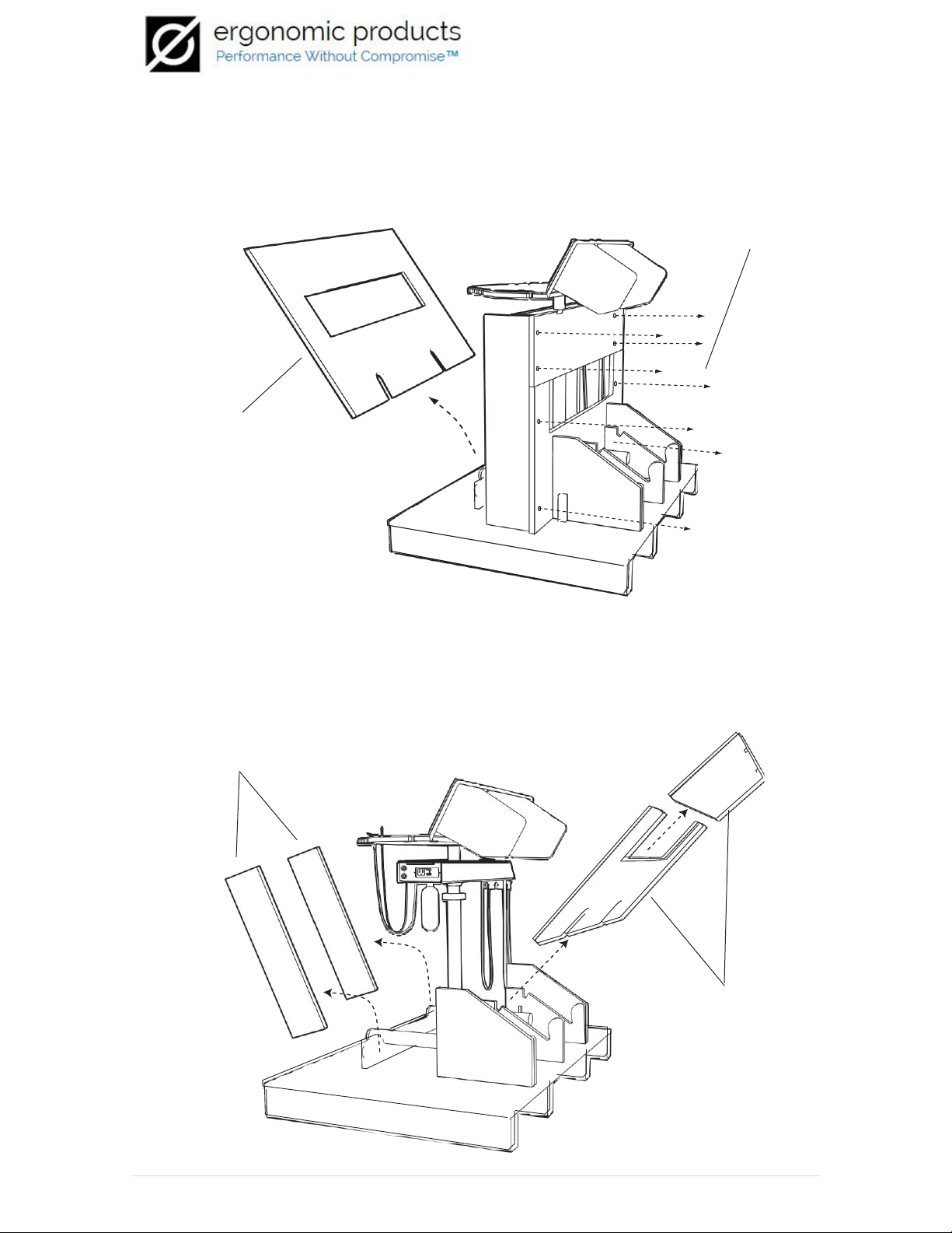
2.
Remove Top Tier Assembly from rear of container and set aside. Using a Phillips
screwdriver, remove the six (6) screws from the front face of the container. (Fig. 2)
top tier
assembly
six (6) phillips screws
Fig. 2
4
3.
Remove the front face plate and set aside. Proceed to the rear of container and
remove the eight (8) Phillips screws from the upper and lower sections of the rear
face plate. (Fig.3)
Eight (8) Phillips Screws
Front Face Plate
Fig. 3
4.
Remove the rear face plate sections & side supports and set aside. (Fig. 4)
Side Panels
Rear Panels
Fig. 4

5
5.
Safely lift Workstation Assembly from container base and place on floor. (Fig. 5)
Important: Practice safe lifting procedures & use a partner to remove
workstation from container base.
Fig. 5
6.
Retrieve Top Tier Assembly (if applicable) and align the Top Tier Support Shafts
with the holes in the Workstation Assembly worksurface. Once in place, fasten the
Top Tier Assembly in place with the Support Shaft Lock Nuts. (Fig. 6)
Top Tier Assembly
Workstation Assembly
Top Tier Support Shafts
Support Shaft Lock Nuts
Fig. 6
Congratulations! Your Ergonomic Products Workstation is now fully assembled!

6
Section 3 - installation
Umbilical Installation
All of the utilities required by your Workstation are supplied via the Umbilical Tube. Installation simply involves
plugging in tubing and electrical connectors. After connections are made, install hose clamp and umbilical
cover.
1.
Plug in 9 pin power connector and tubing connector. (See fig. 7)
Be Careful not to cut or damage any of the tubes and wires inside the umbilical tube.
9 Pin Power connector
Black, yellow, red wires on top
Tubing Connector:
Move lever clockwise to install or
remove; Move counter
clockwise to lock
Fig 7
2.
Plug suction hose onto copper tube. Run USB cord through hole and make appropriate
connections. (See fig. 8)
USB Port
120 V Outlet
Fig. 8
7
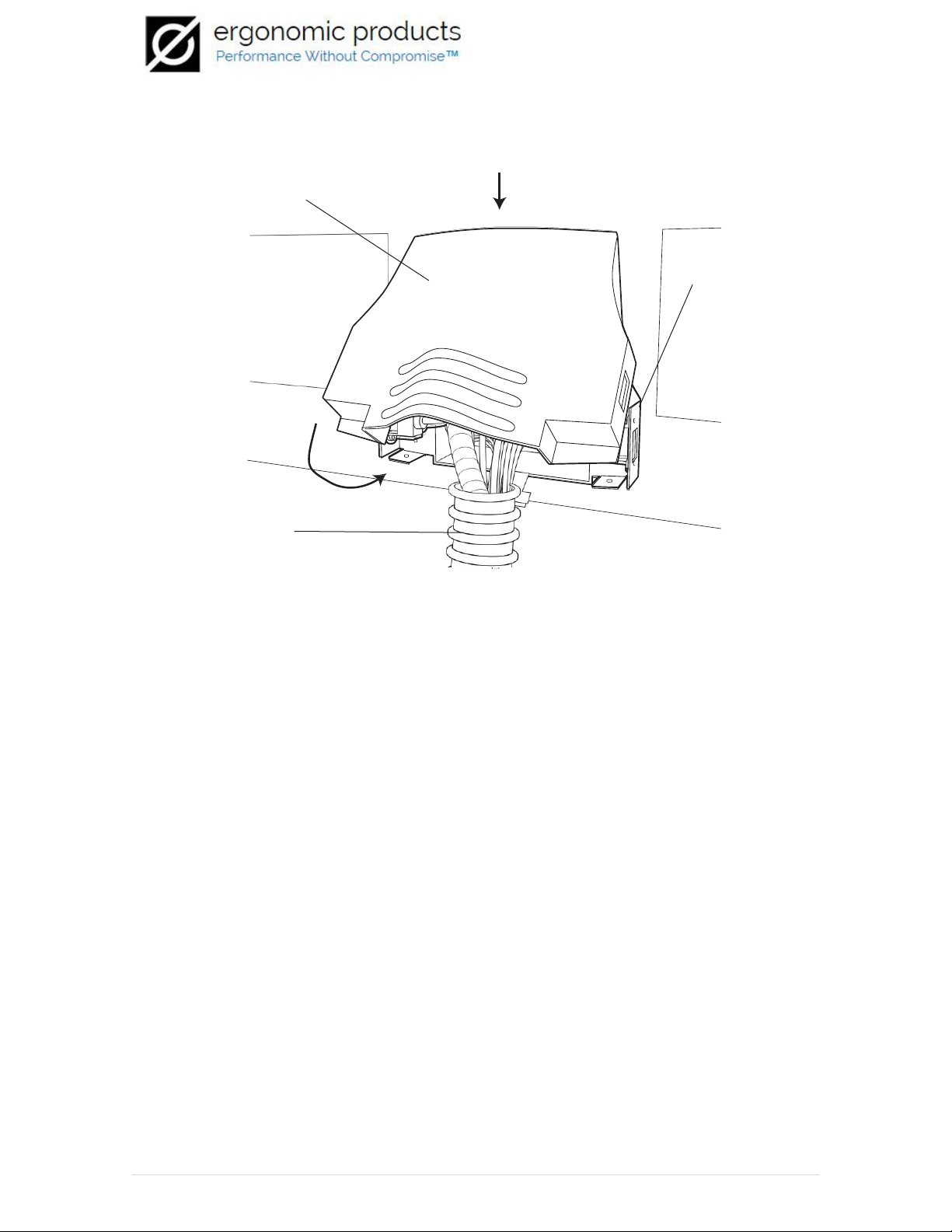
3.
Securely attach umbilical hose to chassis with hose clamp. Hook cover on tab at
top and fasten with the 2 screws on bottom corners. (See fig. 9)
Umbilical Cover
Umbilical chassis
Umbilical
hose
Fig. 9

8
Section 4 - USB Keyboard connection
Your Ergonomic Products Workstation supports USB (Universal Serial Bus) for connections to a Mac or PC computer
keyboard (not supplied). The following section describes the connection process.
1.
Remove both Keyboard Slide Bracket Screws with a 1/8” Allen wrench (supplied). Locate both
Top Tier Set Screws and loosen with the supplied 5/32” Allen wrench (supplied) until Top Tier can
be lifted away from posts. (Fig. 10)
Top tier set screw (detail)
Keyboard
slide bracket
screws
(2)
Top tier set screws (2)
Fig. 10
2.
Lifting the Top Tier Worksurface away, run USB cable from a USB Keyboard (not supplied)
down the length of the slotted support shaft and replace the Top Tier Worksurface. Re-tighten
the Top Tier Set Screws and replace the Keyboard Slide Bracket Screws. (Fig. 11)
Top tier work surface
USB cable (from USB keyboard)
Top tier support shaft
w/slot
Fig. 11

9
3.
Under the Lower Worksurface, plug the male end of the USB cable (from Key-
board) into the female USB receptor on the Power Channel® and the keyboard
connection is complete. (Fig. 12)
Lower work surface
Top tier support shaft
Power Channel®
USB Cable
(From USB Keyboard)
Fig. 12
Section 5 - Worksurface height adjustment
Your Ergonomic Products Workstation is height adjustable. To adjust the worksurface height to your personal
preference, read the following section.
To Adjust: Loosen the Height Adjust Set Screw on the Workstation Support Post Coupler
and raise or lower the worksurface (in one inch increments) to the desired height and then
re-tighten the set screw. (Fig. 13)
Workstation
support Post
coupler
Workstation support
Post
Height adjust set screw
Height adjustment detent(s)
Fig. 13
Important: The height adjustment is only complete when the set screw is in contact with a
height adjustment detent.

10
Section 6 - Accessing the Power Channel® Interior
Only a licensed dental service technician should attempt to service your Ergonomic Products Workstation. This
section is to show the proper way to gain access to the interior of the Power Channel® on your workstation.
1. Depress Saliva Trap Canister until it slips under Power Channel® chassis. (Fig. 14)
note: If vac is shut off, removing canister cover allows for more clear
Saliva trap canister
Power channel®
Chassis
Fig. 14
2. Remove Chassis Thumb Screw & water bottle from the rear of the Power Channel® and set
aside. (Fig. 15)
Chassis thumb
screw
Water bottle
Fig. 15

11
3. Slide the Power Channel® Chassis forward until the six (6) alignment tabs are
aligned with the Power Channel® Cover. (Fig. 16)
Power channel®
Cover
Power Channel® Chassis
Alignment tab(s)
Fig. 16
4. When tabs are aligned, the Power Channel® Chassis can be lowered to disengage it
from the Power Channel® Cover. (Fig.17)
Note: Sliding Power Channel® cover upwards facilitates Power Channel® Chassis removal.
Power Channel®
Cover
Power Channel® Chassis
Fig. 17
NOTE: Reverse steps 1-3 to re-install

12
Section 7 - Utility Connections
13
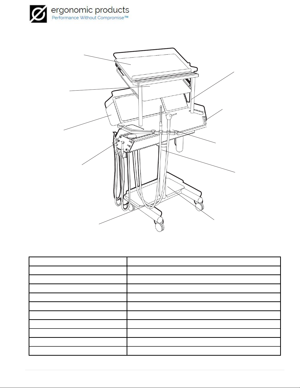
Section 8 - Basic anatomy of an Ergonomic Products Workstation
Top tier
worksurface
Top tier
support post
Keyboard slide
Lower worksurface
Consumable bins
Power channel®
Power channel®
faceplate
Worksurface
support post
H-Frame
Base
Trash shelf
Section 9 - Technical Specifications
Dimensions (Single Tier)
30”w, 25
1/2
”d, 30”h
Dimensions (Two Tier)
30”w, 25
1/2
”d, 48 1/2”h
Weight
88 lbs
Plumbing Requirements (general)
1/2” copper pipe stub for vacuum
Plumbing Requirements (air)
3/8” Compression fitting w/valve
Plumbing Requirements (water)
3/8” Compression fitting w/valve
Electrical Requirements (general)
(1) 120V 15A - GFI outlet (quad)
Cure Light Info (standard)
120V, 0.5A
UltraSonic Info (optional)
120V, 1.5A
Electric Handpieces (optional)
120V,1.25A
Handpiece illumination (Standard)
120V, 0.6A

14
A PROMISE FROM THE EMPLOYEES AT ERGONOMIC PRODUCTS, INC.
At Ergonomic Products, Inc., we understand that placing a dental equipment order, whether it be with a
local distributor, one of the big names in the industry or a specialty firm like ours, can be difficult. We
understand your fears in making such an investment. Whether your order is large or small, we promise
to treat every customer with the same level of complete honesty and courtesy. We know you won’t get
this kind of commitment everywhere you go.
We promise to give you answers to your technical questions as quickly as possible. Our technical people
are working diligently every day to deliver the finest equipment. When a service need does occur, we
will take full responsibility and do everything in our power to correct the problem.
We promise to always truthfully describe our products and the technology they provide you with. We
are sure that our equipment is absolutely the best available. Period. We believe that it will tell its own
story. We will never sell you more than our equipment can deliver. Life is too short for that.
We promise to offer you a significant warranty on our products that we will unequivocally stand behind.
• 10-year limited warranty on all Corian®surfaces*
• 5-year warranty on all RapidCarts®**
•
• 3-year warranty on all Workstations®
• 1-year warranty on all storage tubs and bins
• 3rd party components carry the original manufacturer’s warranty:
o 1-year warranty on scalers
o 1-year warranty on curing lights
o
o 1-year warranty on BienAir Electric Motors
* Limited to manufacturer’s defects only
** Excludes powder coated RapidCarts®tops (1 year warranty)
**** Excludes bulbs
We promise to offer you prompt, inexpensive repairs. Products under warranty will, of course, be fixed
as quickly as possible and service will be done on site if feasible. If it must be returned to our technical
center, it will be returned to you without additional shipping charges. If the time needed to repair it will
affect your practice schedule, we will try to provide a loaner so as to not interrupt your service to your
patients. In an emergency, our Doctor Delivery Power Channels® will ship overnight. The entire new
unit can be placed in service in 45 minutes or less. No one else in the industry can come close to this
level of response. Further, if a warranty does not apply, we will quickly repair your product and promise
that our repair costs are very modest.
Should your office damage equipment, due to improper use or inadequate installation or maintenance,
we’ll still make sure to fix your problem, promptly and without complaint.
We promise to continuously satisfy you with our products and services. We think of our customers as
friends. We want to hear from you and help you improve your practice.
Sincerely,
The Staff at Ergonomic Products, Inc. 1-866-ERGO-4-US
Table of contents


