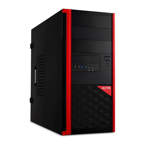
Altos P30 F6 User manual

Workstation
User Guide

© 2013. All Rights Reserved.
Altos Workstation
User Guide
Model Number :
Serial Number:
Purchase Date:
Place of Purchase:

1 System setup
System notes
System controls and indicators
Front panel controls
Front panel LED indicator
status Rear panel controls
Setting up the system Pre-
installation requirements
Turning on the system
Power-on problems
Turning off the system
Configuring the hard disk drive
Replacing components
Replacing the heatsink fan assembly
Replacing the processor
Replacing the hard disk
Upgrading the system memory
Installing an expansion card
Installing a SAS card
System troubleshooting
Resetting the system
Initial system startup problems
Initial troubleshooting checklist
Hardware diagnostic testing
Checking the boot-up status
Specific problems and corrective actions
Notices
Regulations and safety notices
1
C
o
n
t
e
n
t
s
2
3
3
4
5
7
7
8
8
9
10
11
11
15
20
21
23
23
25
25
25
25
26
26
27
31
31

iv

1 System setup

21 System setup
System notes
Thank you for purchasing your Altos workstation. This user guide is
intended as a reference for experienced workstation technicians and
helps detail many of the features available in Altos workstations. For more
detailed information about any particular component or software solution,
you may consult the technical specifications or the user manuel for that
application.
Note: Before opening or removing any components please
contact your local certified Altos service representative.
Warning: Any parts or components damaged during replacement by
a non-certified technician are not covered by the warranty. For
details, please consult the warranty guide from your system.

3
System controls and indicators
Front panel controls
Icon
Component
Description
Power button
Press to turn the workstation on/off, or
to put it in standby mode
Power indicator
Indicates the system power status.
HDD activity
Indicates the status of a system hard
indicator
disk drive.
System status/fault
Indicates the status of the system
indicator
operations.
LAN port 1 activity
Indicates the system network 1
indicator
connection status.
LAN port 2 activity
Indicates the system network 2
indicator
connection status.
System ID switch/
Indicates if the system ID button is
indicator
pressed or activated through IPMI.
USB 2.0 ports
Connect to USB devices.
USB 3.0 ports
Connect to USB devices.

41 System setup
Front panel LED indicator status
LED
LED
LED state
Status
indicator
color
Power state
Green
On
S0: Power On
indicator
Green
Blink (1 Hz with at
S1: Sleep
50% duty cycle)
N/A
Off
S4
N/A
Off
S5
HDD
Green/
Blink
HDD access
activity
Amber
indicator
N/A
Off
No access and No HDD fault
System
Red
On
CPU overheat
status1
Red
Fast blink (once
Fan failure
per second)
Red
Slow blink (once
Power failure
every 4 seconds)
N/A
Off
Normal
System
Green
On
System ready/No alarm
status2
Green
Blink
System ready but some CPU
functions and DIMM may be
degraded or damaged
Red
On
Critical alarm
Red
Blink
Non-critical alarm
N/A
Off
System not ready (POST
error/NMI event/CPU or
terminator missing, … etc.)
LAN activity
Green
On
LAN link/No access
indicators
Green
Blink
LAN access
LAN1
N/A
Off
Disconnect/Idle
LAN2
System ID
N/A
Off
Normal
indicator
Blue
On
System ID button pressed.3
Blue
Blinking/On
IPMI-activated system ID
1 For single color system.
2 For dual colors system.
3 For 310/320 F2, the system ID indicator stays lighted while BMC is initializing.

5
Rear panel controls
Icon
Component
Description
Management port
Reserved for remote management.
(10/100)
PS/2 mouse port
Connects to a PS/2 mouse.
PS/2 keyboard port
Connects to a PS/2 keyboard.
USB 2.0 ports
Connect to USB devices.
USB 3.0 ports
Connect to USB devices.
Video port
Connects to monitors.
Gigabit LAN port
Connects to an internet or intranet
network.
Serial port
Connects to serial devices.

61 System setup
LAN port LED indicator status
LED
LED color
LED state
Status
indicator
RJ45 LED
N/A
Off
No connection or
(left)
10 Mbps
Green
On
100 Mbps
Amber
On
1000 Mbps
RJ45 LED
Amber/
On
Active connection
(right)
Green
Amber/
Blinking
Transmit/Receive activity
Green

7
Setting up the system
Pre-installation requirements
Selecting a site
Before unpacking and installing the system, select a suitable site for
the system for maximum efficiency. Consider the following factors
when choosing a site for the system:
•Near a grounded power outlet.
•Clean and dust-free.
•Stable surface free from vibration.
•Well-ventilated and away from sources of heat.
•Secluded from electromagnetic fields produced by electrical
devices such as air conditioners, radio and TV transmitters, etc.
Checking the package contents
Check the following items from the package:
•System unit
•Accessory box
If any of the above items is damaged or missing, contact your
dealer immediately.
Save the boxes and packing materials for future use.

81 System setup
Turning on the system
After making sure that you have properly set up the system, applied
power and connected all the necessary peripherals, you can now power
on the system. Follow the procedure below.
1 Press the power button .
The system starts up and displays a welcome message on the monitor.
After that, a series of power-on self-test (POST) messages appears. The
POST messages indicate if the system is running well or not.
Note: If the system does not turn on or boot after pressing the
power button, go to the next section for the possible causes of the
boot failure.
Aside from the POST messages, you can determine if the system is
in good condition by checking if the following occurred.
•The power status indicator on the front panel lights up blue.
•The Num Lock, Caps Lock and Scroll Lock indicators on the
keyboard light up.
Power-on problems
If the system fails to boot after you have applied power, check the
following factors that might have caused the boot failure.
•The external power cord may be loosely connected.
Check the power cord connection from the power outlet to the power
cord socket on the rear panel. Make sure that the cord is properly
connected to the power outlet and to the power cord socket.
•No power comes from the grounded power outlet.
Have an electrician check your power outlet.
•Loose or improperly connected internal power cables.
Check the internal cable connections. If you are not confident
to perform this step, ask a qualified technician to assist you.
Warning! Make sure all power cords are disconnected from
the electrical outlet before performing this task.

9
Turning off the system
There are two ways to turn off the workstation—via software or via
hardware. The software procedure below applies to a system running on
a Windows OS. For other shutdown procedures, refer to the related user
documentation.
To turn off the system via software:
1 Press <Ctrl> + <Alt> + <Delete> on the attached keyboard or
click Start on the Windows taskbar.
2 Select Shut Down.
3 Select Shut Down from the drop-down menu, then click OK.
To turn off the system via hardware:
If you cannot shut down the workstation via software, press the power
button for at least four seconds. Quickly pressing the button may put
the workstation in a Suspend mode only.

10 1 System setup
Configuring the hard disk drive
By default, the system is shipped with only one hard disk drive bay. To
install additional hard disk drives in the second hard disk drive bay,
you need to purchase the optional bay.
Note: Maximum HDD support is SKU-dependent.

11
Replacing components
The following sections show you how to replace certain components
in your workstation.
Note: The drawings of the components are for reference only.
The actual components may vary slightly.
Replacing the heatsink fan assembly
Notes:
•Always connect the power cord last and always remove it before
adding, removing or changing any hardware components. Make
sure that you install the processor in the CPU socket before you
install the CPU heatsink fan assembly.
•If you buy a processor separately, make sure that you use an
Altos-certified multidirectional heatsink fan assembly only.
•Make sure to install the mainboard in the workstation before
you install the CPU heatsink fan assembly.
•When receiving a mainboard without a processor pre-installed, make
sure that the plastic CPU socket cap is in place and none of the socket
pins is bent; otherwise, contact your retailer immediately.

12 1 System setup
Removing the heatsink
Warning! We do not recommend that the processor or the
heatsink assembly be removed. However, if you do need to
uninstall the heatsink fan assembly, please follow the
instructions below to prevent damage to the processor or
the CPU socket.
1 Open the workstation and locate the heatsink.
2 If your heatsink has a fan assembly, remove the fan cable from
its mainboard connector.
Note: Some workstation models use a passive heatsink design which
does not include a fan assembly.

13
3 Using a screwdriver, loosen the heatsink screws from the
mainboard and detach the heatsink.
(1) Lay down the heatsink in an upright position —with the thermal
patch facing upward. Do not let the thermal patch touch the
work surface.
Installing the heatsink
Caution! The heatsink has a thermal interface material (TIM) on the
underside. Use caution so that you do not damage the TIM. If a
protective film is installed on the TIM, remove it.
1 Open the workstation and locate the heatsink connector.
2 Do not apply any thermal grease to the heatsink or the processor
die; the required amount has already been applied.
3 Align then insert the heatsink on top of the retention plate.

14 1 System setup
4 Use a long-nosed screwdriver to tighten the heatsink screws to
secure it to the mainboard.
5 If your heatsink has a fan assembly, connect the fan cable to
its mainboard connector.

15
Replacing the processor
Warning! The processor becomes very hot when the system is
on. Allow it to cool off first before handling.
Before you replace the processor, kindly check if you have a type 1 or
2 processor and follow the instructions accordingly.
For type 1 processor
1 Remove the heatsink fan assembly (see "Removing the
heatsink" on page 12).
2 Remove the default processor.
(1) Press down on the load lever then release out of the retention tab.
(2) Rotate the load lever to the fully open position until the
retention plate is completed lifted.
(3) Grasp the processor by its edges and lift it out of its socket.
(4) Store the old processor inside an anti-static bag.
3Remove the new processor from its protective packaging.

16 1 System setup
4 Install the new processor.
(1) Hold the processor by its edges then insert it in the socket.
Make sure that the alignment tabs on the socket fit the two
notches located on the edges of the processor. The pins are
keyed in such a way that you cannot install the processor in the
wrong orientation without bending the pins.
(2) Close the retention plate.
(3) Slide the retention plate tab under the retention knob.
(4) Engage the load lever back in place and secure the load
lever under the load lever retention tab.
5 Apply the thermal interface material.
(1) Use an alcohol pad to wipe off the old thermal grease from both
the HSF assembly and the processor socket retention plate.
(2) Apply a thin layer of thermal interface material before installing
the HSF.
Make sure that only a very thin layer is applied so that
both contact surfaces are still visible.
6 Install the heatsink fan assembly (see "Installing the heatsink"
on page 13).
This manual suits for next models
1
Table of contents
Other Altos Desktop manuals

Altos
Altos 580 Manual

Altos
Altos 486 Setup guide

Altos
Altos BrainSphere P555 F5 User manual

Altos
Altos BrainSphere P15 F7 User manual

Altos
Altos 586T User manual

Altos
Altos BrainSphere P130 F5 User manual

Altos
Altos 486 User manual

Altos
Altos 586 User manual

Altos
Altos P550 F4 User manual

Altos
Altos 986T User instructions