ERGONOMIC SOLUTIONS 2ESP-WA-C48-SLV User manual

ASSEMBLY AND OPERATION
WEIGHT ADJUSTABLE
ESPREE Model 2ESP-WA-C48-___
Model 2ESP-WA-C60-___
___ = SLV, BLK or WHTPNEUMATIC TABLE BASE
2ESP-WA Rev B 8/17

2
WEIGHT ADJUSTABLE ESPREE PNEUMATIC TABLE BASE PARTS AND TOOLS
PLEASE REVIEW these instructions before beginning the assembly procedures. Check that all the parts shown
below were provided with your order. Contact your supplier if any materials are missing. Do not discard the
packaging until content that the product operates to your satisfaction.
ADDITIONAL TOOLS REQUIRED
• #2 and #3 Phillips screwdriver • Rubber mallet
• 3/8" ratchet or manual driver*
PARTS AND TOOLS PROVIDED
Frame Assembly (1)
Adjustable Feet (2)
10mm Hex Bit*,
3
/8" Drive (1)
Allen Keys (1 each)
Cable Clip (1) Fasteners
Top Support
End Cap (4)
5mm 6mm
CAUTION: Hand-tighten screws only.
M8x40 SHCS (7)
M8x14 SHCS (4)
M8x25 FHCS (1)
#12x2¾ PPH (10)
Plastic Clip (8)
#8x½ PPH (5)
IMPORTANT: The columns of this table contain high force pneumatic springs that are sized to lift the work
surface and its contents. Proper sizing, handling, and assembly is critical to prevent damage to the columns
or serious injury. All persons not involved in the installation should remain at a safe distance until set-up is
Review the lift rating decal on the frame to learn the minimum and maximum lift weight for the unit. The lift
weight is the total weight of the work surface and the contents it supports.
*DO NOT USE A POWER DRIVER WITH THE 10mm HEX BIT. THIS WILL VOID THE WARRANTY.
WARNING: Do not activate the release lever until the table is fully assembled and
in the upright position. Do not remove any bolts or hardware from the leg columns. Do not
remove the safety pins, warning tags, and warning labels until the table is fully assembled
and in the upright position. Sudden extension of the table legs may cause serious injury if
these instructions are not followed.
CAUTION: Always check that screws
used to attach components to the
work surface are not too long for the
thickness of the surface.
Work
Surface
Ratchet Clip (1)
Note: If installing a keyboard tray please see page 8, step 11.
3mm
3
ASSEMBLY WEIGHT ADJUSTABLE ESPREE PNEUMATIC TABLE BASE
IMPORTANT: This is a heavy product. We strongly recommend that two people lift this product from the
packaging. In addition, whenever the product is re-arranged (such as turning the table over) two people
should be employed in the process.
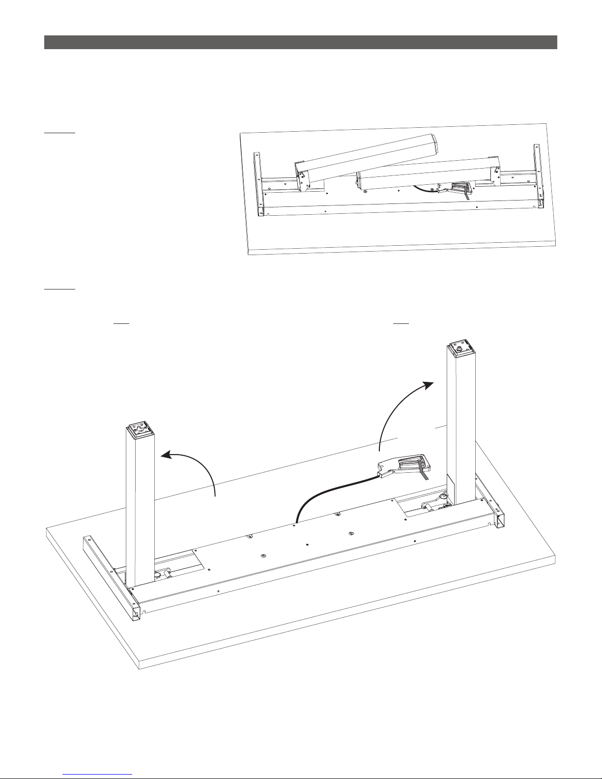
STEP 1
Arrange the worksurface and frame
assembly.
• Lay the tabletop face down on a
soft, clean surface.
• Remove the frame assembly from
its packaging and center the
assembly on the worksurface.
STEP 2
Raise the table legs to the vertical position.
WARNING: Do not remove the safety label on the release handle and do not remove the safety pins
securing the legs until the table is fully assembled and in the upright position.
Do not
engage
handle!
4
WEIGHT ADJUSTABLE ESPREE PNEUMATIC TABLE BASE ASSEMBLY
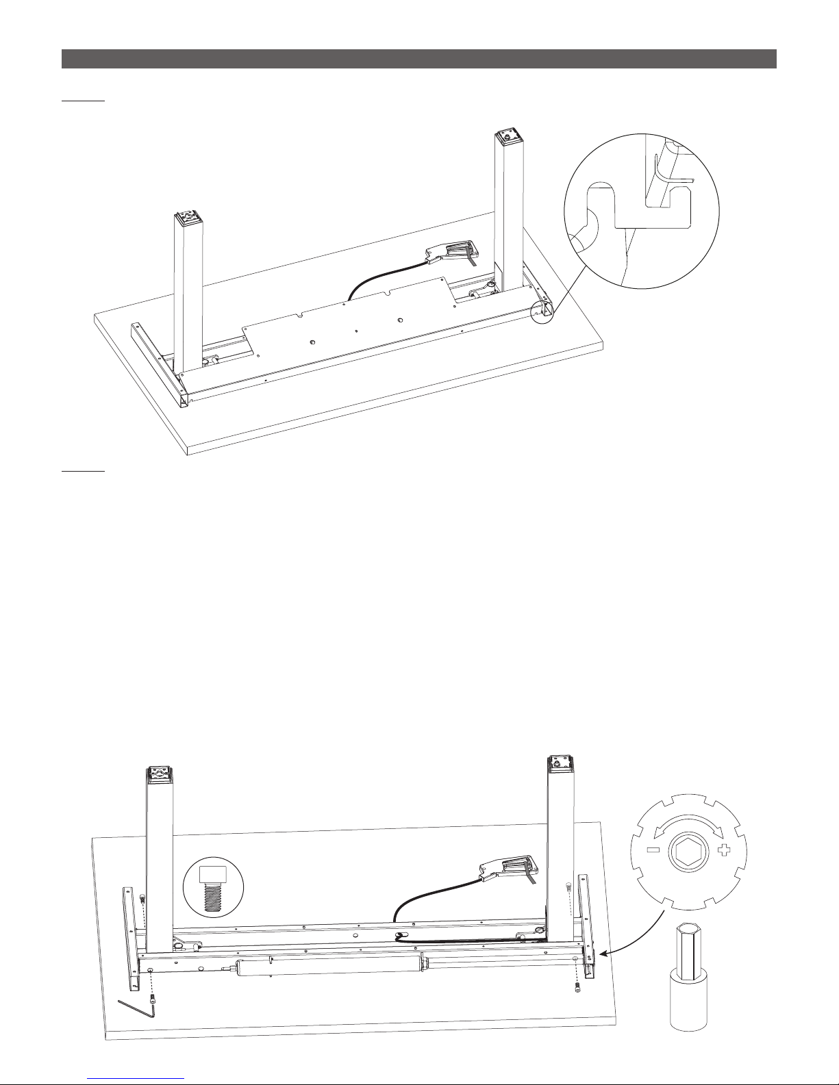
STEP 3
Remove the cover by releasing the two hooks from the cut-outs.
STEP 4
Secure the legs in the vertical position with the four M8x14 screws.
• Use the 5mm Allen key.
— Align the hole on each side of the leg column with the hole in the frame channel by rotating the leg
column.
• If necessary, use the 10mm hex bit to rotate the square drive rod to gain access to the left rear screw
hole.
— The hex adjustment is located on the side of the top support, as shown.
—
Remove Cover
leg column and the hole in the frame channel is most easily done by inserting the Allen key through
the hole in the frame channel and the hole in the leg column. Then hold the leg in place and drive
the screw.
Rotate the bit clockwise only. (Do not go below 0-0 on the gauge; do not rotate the bit
counterclockwise.)
Note: A small spacer or box may be helpful to hold the frame in the proper position. The alignment of the
M8x14 Front
Rear
Rotate Square Drive Rod,
If Necessary to Install Screw
10mm
Hex Bit
5
ASSEMBLY WEIGHT ADJUSTABLE ESPREE PNEUMATIC TABLE BASE
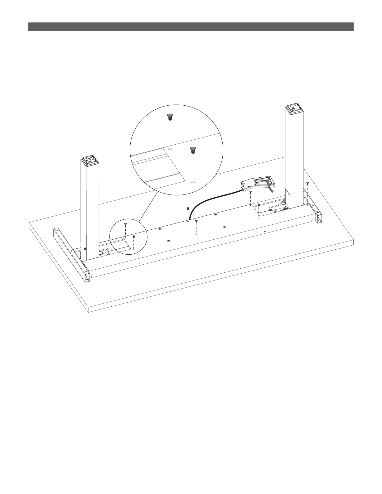
STEP 5
Re-install the cover.
• Insert the two hooks back into the cut-outs (see step 3).
• Insert the eight plastic clips where shown to secure the cover in position.
IMPORTANT: The cover must be re-installed to shield the user from moving components.
Plastic
Clip

6
Right-Side
Column
Left-Side
Column
M8x40
5mm
Allen Key
M8x40
5mm
Allen Key
WEIGHT ADJUSTABLE ESPREE PNEUMATIC TABLE BASE ASSEMBLY
STEP 6
Change the length of the adjustable feet, if necessary.
• The length of the feet may be either 22" (55.9cm) or 28" (71.2cm). The feet are shipped in the 28" length.
•
four base screws, and the 3mm Allen key for the two smaller screws.
• Slide the feet to the 22" length and reinstall the four screws with the 5mm Allen key.
STEP 7
Attach a foot to each of the legs.
Refer to the illustrations.
• The left side foot is attached with
four M8x40 screws using the 5mm
Allen key.
• The right side foot is attached with
three M8x40 screws and one
M8x25 screw. The M8x25
insert on the leg column.
Tighten it with a 5mm Allen key.
Adjustment
Plate
5mm
Allen Key
Slide In
22"
Adjustable
Length
28"
3mm
Allen Key
M8x25

7
ASSEMBLY WEIGHT ADJUSTABLE ESPREE PNEUMATIC TABLE BASE
STEP 8
Use a rubber mallet to install the four end caps into the open
ends of the top supports.
• Tap the end caps with the mallet to secure them in position.
STEP 9
Adjust the position of the frame before screwing
it to the table.
• The frame should be centered from side to side.
• The rear of the feet should align with the rear
of the table, and the rear of the cover should be
5" from the rear of the table.
STEP 10
• Use the ten #12x2¾ pan head screws and a #3 Phillips screwdriver.
Align Rear of Feet with Rear of Table
5"
Center Frame Side to Side
End Cap
Top
Support
#12x2¾

8
STEP 11
Attach the release lever at the front of the table
on the left or right side for easy access by the user.
• Use four #8x½ screws to attach
the lever to the underside of the
worksurface.
• Slide the cable clip over the release
lever cable. Position the clip to support
the cable from sagging and attach
it with the remaining #8x½ screw.
IMPORTANT: When securing the cable,
the cable should be gently curved to
ensure smooth operation. Do not kink
the cable or form corners with it.
STEP 12
IMPORTANT: There must be 1" (25mm) of clearance on all sides of the worksurface (and other moving parts)
to ensure free, unobstructed movement.
• Adjust the leveling glides on the feet to level the worksurface, if necessary.
•
is important when testing operation.
WEIGHT ADJUSTABLE ESPREE PNEUMATIC TABLE BASE ASSEMBLY
Place all contents that will be used
on the worksurface before testing
operation. Examples:
• Monitor(s)
• Keyboard
• Mouse
• Laptop
• Docking station
• Light
Note: If you plan to install a keyboard tray please
attach the release lever on the left side of the
worksurface to avoid cross over issues.
Cord
Clip

9
OPERATION WEIGHT ADJUSTABLE ESPREE PNEUMATIC TABLE BASE
STEP 13
Test operation.
• Verify that the weight of the worksurface and contents is within the lift rating shown on the bottom of the
frame.
• Lightly press your hand onto the table top as a safeguard. Remove the safety pins one by one on both
sides with your other hand and store them so that the frame can be fully secured for transport at a later
time.
IMPORTANT: The safety pins and release lever warning lable must be removed or else the table will not
operate.
• Check operation by pulling the release lever toward you with one hand and using the other hand to raise
or lower the table.
WARNING: The table may suddenly raise upward or fall downward when the release lever is pulled. The
table is designed to be balanced when the weight of the worksurface and its contents is at the midpoint
of the load rating.
Remove
Safety Pins
Pull Release Lever

10
WEIGHT ADJUSTABLE ESPREE PNEUMATIC TABLE BASE ADJUSTMENT
STEP 14
Using a ratchet wrench or manual driver with the 10mm hex bit provided, adjust the pneumatic force by
turning the hex adjustment found on the side, next to the gauge.
• See the graph below right for a 48" table base. At the 0/0 gauge reading, weight is set for just under 50
lbs. That moves up slowly to about 60 lbs at the 4/0 gauge reading and then increases more rapidly, to
over 100 lbs at the 8/0 gauge reading. Do not adjust past the 8/0 setting due to risk of damage.
• If you know the approximate weight of the table top (work surface plus contents), you can go to the
gauge reading for that weight.
• The goal in making this adjustment is to equalize the force needed to raise the table with the force
needed to lower it.
IMPORTANT: Retain the 10mm hex bit for future adjustments. Be careful not to misplace it.
STEP 15
Adjust cable tension, if necessary.
• If the table does not lock into place when the lever is released, tighten the cable adjustment nut one-half
turn and recheck.
• If the table stays locked in one place or moves slowly, loosen the cable adjustment nut one-half turn and
recheck.
• Call ESI Customer Service if you
have questions about operation
or adjustment.
IMPORTANT: Cable tension is
pre-adjusted at the factory.
Do not perform this adjustment
yourself unless absolutely necessary.
10mm
Hex Bit Gauge Reading
Pounds
A setting lower than 0/0 or
higher than 8/0 is not permitted.
00
150.0
100.0
50.0
0.0
48" Table Base
0.0
1.0
2.0
3.0
4.0
5.0
6.0
7.0
8.0
8mm
Wrench

11
OPERATION WEIGHT ADJUSTABLE ESPREE PNEUMATIC TABLE BASE
OPERATION
IMPORTANT: When raising or lowering the table, always make sure area is cleared of any obstructions or
pinch points.
• Pull the release lever toward you with one hand and using the opposite hand to raise or lower the table.
WARNING: The table may suddenly raise upward or fall downward when the release lever is pulled. The
table is designed to be balanced when the weight of the worksurface and its contents are at the midpoint
of the adjusted load rating.
Tool Storage: A ratchet may be conveniently stored in on the front of the table base by utilizing the ratchet
clip featured below. Please note, if storing the ratchet with the 10mm hex bit still attached, simply face the
ratchet outwards.
If bit attached,
face outward

800.833.3746 esiergo.com
© 2017 ESI Ergonomic Solutions. All rights reserved. 2ESP-WA Rev B 8/17
This manual suits for next models
5
Table of contents
Other ERGONOMIC SOLUTIONS Indoor Furnishing manuals


Popular Indoor Furnishing manuals by other brands


Whalen
Whalen AVCEC65-TC Assembly instructions

Mobalpa
Mobalpa FTAA1980 Mounting instructions

TUHOME Furniture
TUHOME Furniture MULTIUSOS MLB 4469 Assembly instructions

Argos
Argos Washington Assembly instructions

Gami
Gami H67-LENA 193 Assembly instructions

Accentrics Home
Accentrics Home D192-272 Assembly instruction


