Erica Synths SUPER-SYNCABLE VCO User manual

GUIDE ON ASSEMBLY OF THE ERICA SYNTHS SUPER-SYNCABLE VCO
If you are reading this, most probably, you are about to build Erica
mechanical construction and doesn’t require wiring. The core of the
VCO is borrowed from Polivoks VCO and in exponential converter we
use the original matched transistor IC that was used in Polivoks synth.
1) we introduced +-10V regulators for greater stability of operation
and eliminated need for voltage references on opamps,
2) we adjusted signal amplitudes to match requirements of
contemporary modular synths
3) we introduced PWM circuit for greater variety of sound
4) we introduced 7 octave range switch, and the VCO tracks well
over7 octaves
5) we optimized Pulse width schematics
6) but most importantly – we implemented unique Sync option that
allows to sync the VCO on Rising or Falling edge of Sync in signal.
Sync edge switch allows VCO to be locked to either rising or falling
edge of the input wave. This feature has many uses:
As the input sync wave can be of any character and from any source,
on arbitrary waves one edge may work better then the other.
Even when wave outputs of master and slave oscillator are simply
mixed together, sync lock edge will determine the resulting shape due
synced wave is square or saw, and the master is triangle or sine, edge
cancellation or boosting of the fundamental tone. When oscillators are
multiplied (ring modulated) together, especially with complex waves,
(shifted) parts of waves will get multiplied together.
Furthermore, if sync source wave is a PWM, sync edge setting
determines if synchronized slave VCO will lock to the static or moving
part of the wave. With dynamic pulse width modulation (especially -
the moving part of input PWM.
Same as in Polivoks VCO case, you can build two VCOs – VCO2 with
Detune (+-2 semitones) option and VCO1 with X-Mod (FM on audio
rate) option. In Polivoks synth VCO1 was frequency modulated by VCO2.
A Syncable VCO kit comes in two versions:
1) Set of 2 PCBs + matched transistor IC + mechanical parts
(PCB connectors, spacers and screws) + 2 rotary switches
2) Set of 2 PCBs + matched transistor IC + mechanical parts
(PCB connectors, spacers and screws) + 2 rotary switches + panel
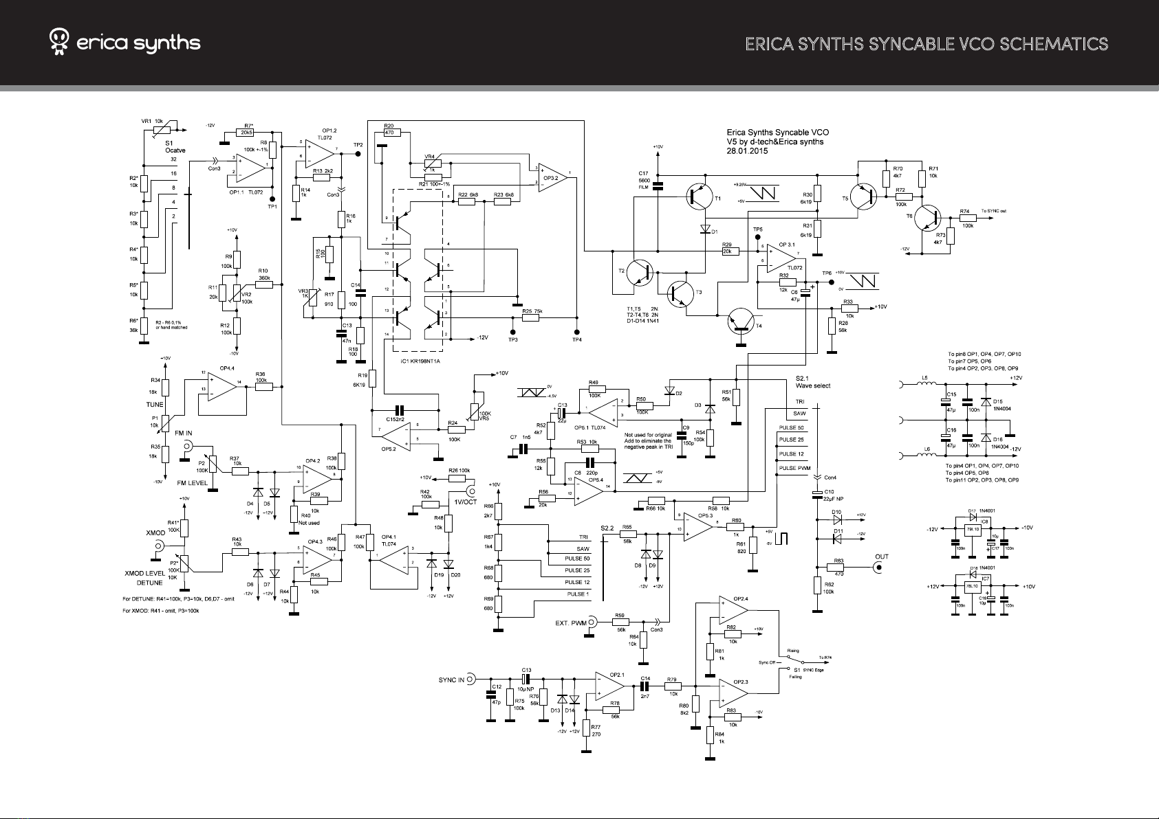
ERICA SYNTHS SYNCABLE VCO SCHEMATICS

BILL OF MATERIALS


ASSEMBLY
1. Take precautions with regard to electrostatic discharge (ESD) safety.
Handling components should be done in electrostatically safe
environment. Use personal and workplace grounding. Any discharge
(even a minor one) from body to a component may permanently
damage it.
correspondingly!
a. For VCO1 (XMOD option): use P3 B100k (we will solder it later),
R44=10k, R27, R41 – omit
b. For VCO2 (Detune option): use P3 B10k (we will solder it later),
R27=1k, R41=56k, R44 – omit, D6, D7 – omit
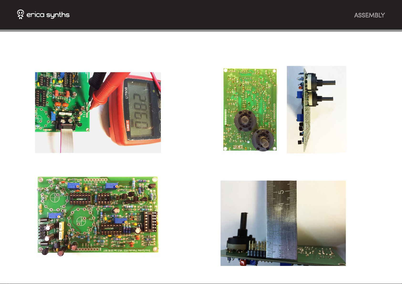
3. Solder all resistors and IC sockets on the TOP PCB! Solder diodes.
Mind the orientation of diodes!
4. Turn TOP PCB around and solder trimpot VR2 (mind the orientation
on the silkscreen) and electrolytic capacitors! Soder capacitors
horizontally as shown on the picture!
5. Populate all passive components, diodes, IC sockets, voltage
regulators and power connector on BOTTOM PCB! (Sorry, there are
few designators with same numbers, but follow the silkscreen
voltage regulator. Luckily we have a solution! Source 79L09, cut its
and you have -10V regulator!
ASSEMBLY
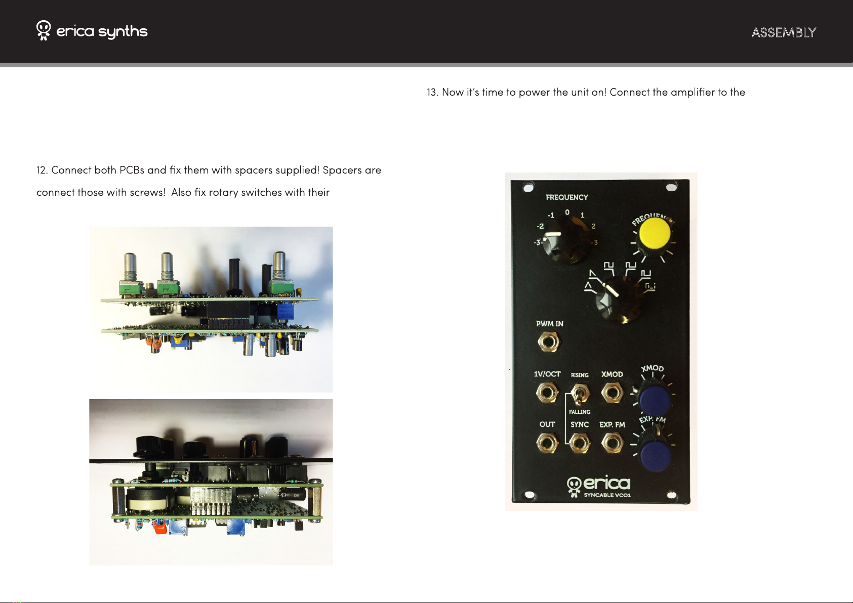
8. Turn Bottom PCB around and solder rotary switches! Note that
Octave Switch is 1x12 position switch, but waveform selector switch is
2x6 position switch! You have to end up with something like this (exactly
like this )!
9. Solder PCB connectors on the BOTTOM PCB! Cut them shorter – they
have to be 12mm long!
6. Now it’s time to make some measurements! Connect a PSU to
BOTTOM PCB and measure, if you get +-12V and +-10V on relevant
connector on the BOTTOM PCB! If you are not getting these voltages,
check, if you have soldered 10V regulators correctly!
7. Complete BOTTOM PCB with transistors!
ASSEMBLY
10. Complete TOP PCB – solder all potentiometers, jacks and PCB
connector sockets!
11. Install rotary switch limiting nuts on both rotary switches! Mind the
number of clicks! For Octave switch it has to be 7, for waveform
switch – 6.
0,5mm short, therefore install nuts between a spacer and PCB and then
washers.
output and listen, if you get some sound! Also check waveforms on
oscilloscope!
14. If you are happy about the result, install the front panel and we are
ready to perform calibration!

CALIBRATION
Ensure all components are placed correctly and soldered well. Check
for possible short circuits that may be left after soldering.
Ensure power supply voltages are as exactly +12.00V and -12.00V as
possible.
Allow some minutes for the VCO to warm up.
Connect a precise voltmeter with range at least +/-15V to the Test Point
1 (TP1).
Set panel FREQUENCY pot to 12 ‘o’clock. When tuning VCO2, set
DETUNE pot to 12 ‘o’clock. Set CV level pots to zero.
Switch around various octave settings. Check the voltage change on
the voltmeter between octaves. Ideally it should be 1.00V per octave.
Tune tirm pot VR1 so that octave steps are as close to 1.00V as possible.
Mostly you can just switch between two center settings, and adjust the
trim pot, only occasionally checking voltages on other settings.
If voltage change step between octave switch steps is wider than
necessary (more than 1.00V), turn the trim pot clockwise. If voltage
change step between octave switch steps is narrower than necessary
(less than 1.00V), turn the trim pot counterclockwise.
If 1.00V steps can only be acquired on certain octave switch settings,
mismatch in octave divder resistor array.
After successful tuning, voltages on the output of octave selector should
be like, for example, -9.62V at -3 (orlowest octave setting), -8.62V at
-2, -7.62V at -1, -6.62V at 0, -5.62V at +1, -4,62V at +2, -3,62V at +3 (or
oscillators, what is important, is the exact 1.00V relation between steps.
Select SAW waveform.
Ensure panel FREQUENCY pot is 12 ‘o’clock, and both modulation pots
are set to zero. When tuning VCO2, set DETUNE pot to 12 ‘o’clock.
Set the octave switch to some middle-low setting, -1 oct for example.
Connect a precise frequency meter or even better – a chromatic tuner
to the VCO module output.
Connect CV keyboard or midi keyboard through midi-CV converter.
Play C4.
standard it is in the middle position.
Note the frequency on the frequency meter of tuner. Play around
several octaves. Check the ratio of frequency relative to the previous
one. Ideally it should change twofold for every octave when going
higher, and should half per every octave step when going lower.
For example: Say, you have written down the frequency X Hz at the
setting C4 (or the tuner shows C4), when playing C5 output frequency
should read 2*X (or tuner show C5).
Tune trim pot VR3 so that octave steps in measured frequency are as
close to the shown above as possible. Mostly you can just play between
two octaves and adjust the VR3, only occasionally checking frequencies
on other octaves.
Turning the trim pot VR3 clockwise with make octave steps narrower,
while turning counterclockwise - wider. Overall tuning will also change
at the same time - this is not a malfunction. So, if the octave frequency
step is too wide, turn the TP3 clockwise a bit, and check the octave step
again. If it is too narrow, turn the TP3 counterclockwise.
---
When you are happy with tuning, play C4 on the keyboard, and check
frequencies on frequency meter or chromatic tuner, when switching
octave switch. You may need to adjust VR1 to get ideal tune, when
changing octaves by octave switch.
---
CALIBRATION
Select SAW waveform.
Ensure panel FREQUENCY pot is 12 ‘o’clock, and both modulation pots
are set to zero. When tuning VCO2, set DETUNE pot to 12 ‘o’clock.
Set the octave switch to 0.
Connect a precise frequency meter to the VCO module output.
Apply 5.00V to CV input.
Obtaining 440Hz at the panel tune knob center position may be
desirable. However it depends on CV source and tuning needs of your
particular setup.
Usually, round integer (x.00V) voltages are tuned to 27.5Hz multiplied
by any powers of two; for example: 5.00V may be tuned to 880Hz (note
A5) for classic Roland, ARP, Sequential Circuits or Moog analog
synthesizer compatibility.
---
If tuning fails:
- Power supply voltages may have changed throughout the process.
- Some components may have been misplaced or missing.
- Improper measurement equipment ground or probe connections
may interfere with oscillator frequency.
This is DIY project for individual use only.
Designed and made in Latvia.
User manual by Girts Ozolins@Erica Synths.
Design by Ieva Andrupe.
Copying, distribution or any commercial use in any way is prohibited
and needs the written permission by Erica Synths.
Speci cations are subject to change without notice.
In case of any questions, feel free to contact us through
www.ericasynths.lv or via e-mail info@ericasynths.lv.
CHECK THE DEMOS OF OTHER ERICA SYNTHS
MODULES ON WWW.ERICASYNTHS.LV
Table of contents
Other Erica Synths Music Equipment manuals


