ERICO TDS-DINLINE User manual

INSTALLATION INSTRUCTIONS
Handbook No:
HB-HBCR-109
© Copyright
ISSUE: 3 April 2003
Includes TDS-AR Alarm Relay
and TDS-SC Surge Counter
SURGE SUPPRESSOR
www.erico.com

INSIDE FRONT COVER
(Blank)

PAGE 3
CONTENTS
Page
1. Warnings ... ... ... ... ... ... ... ... ... ... ... 4
2. Introduction ... ... ... ... ... ... ... ... ... ... 5
3. Quick Installation Guide ... ... ... ... ... ... 5
4. Protection Concepts .. ... ... ... ... ... ... ...
6
5. Mounting ... ... ... ... ... ... ... ... ... ... ...
7
6. Voltage Ratings ... ... ... ... ... ... ... ... ...
8
7. Protection Modes .. ... ... ... ... ... ... ... ... 8
8. Conductor Sizes ... ... ... ... ... ... ... ... ... 10
9. Conductor Length ... ... ... ... ... ... ... ... 11
10. RCD, ELCB ... ... ... ... ... ... ... ... ... ... 14
Page
11. Isolation and Fusing
.. ... ... ... ... ... ... 15
12. Status Indication ... ... ... ... ... ... ... ... 17
13. Maintenance & Testing
.. ... ... ... ... ... 18
14. Alarm Relay (TDS-AR) ..
... ... ... ... ... 19
15. Surge Counter
(
TDS-SC)
... ... ... ... ... 26
16. Typical Domestic Installation
... ... ... 29
17. Extended Warranty
... ... ... ... ... ... ... 30
18. Six Point Plan ... ... ... ... ... ... ... ... ... 31

PAGE 4
DSD INSTALLATION INSTRUCTIONS
1. WARNINGS
• Prior to installation ensure that the unit is
of the correct voltage and frequency, and is
the type recommended for the local power
distribution, and for the equipment being
protected.
• Hazardous voltages may exist internally to
the modules. The units should be installed
(and replaced) only by qualified personnel
in accordance with all relevant Electricity
Safety Standards.
• Do not power three phase connected units
without the upstream neutral connected.
Failure to do so may damage the units and/
or the load.
• Where the unit has an earth terminal, this
must be connected to a low impedance earth
(<10 Ω) for correct operation.
• If connecting to the TDS Opto-coupler
alarm outputs do not reverse the +/-
connections or exceed the maximum
permissible ratings as damage may occur.
• Use only the TDS-AR Alarm Relay with
TDS-DINLINE.
• Use only TDS-SC Surge Counter with TDS
DINLINE.
• Units must be installed in an enclosure or
panel, ensure this does not cause the units
environmental ratings to be exceeded.
• Do not “Megger” or “Flash Test” circuits
with TDS-DINLINE units installed.
• All instructions must be followed to ensure
correct and safe operation.
• Diagrams are illustrative only, and should
not be relied on in isolation.
PAGE 5
2. INTRODUCTION
This Installation Manual details the preferred
procedure for the installation of TDS-
DINLINE™ SURGE SUPPRESSORS and
options.
The TDS-DINLINE SURGE SUPPRESSORS
are available in a variety of surge ratings,
which are packaged in the 2M, 4M and 8M
“DIN 43 880” compliant enclosures. They are
designed to suit many distribution systems
including TN-C, TN-S, TN-C-S (MEN) and TT.
They can be selected for use with distribution
systems with nominal RMS voltages of 110/
120, 220/230/240V or 277V at frequencies of
50/60 Hz.
Recommended installation and connection of
the ALARM RELAY (TDS-AR) is detailed in
Section 14. Installation and connection of the
Surge Counter (TDS-SC) is detailed in section
15.
3. QUICK INSTALLATION GUIDE
Install in the following manner:
1. Ensure that power is removed from the area
and circuits to be connected.
2. Install the DIN mounting rail, if not fitted.
3. Snap lock the Surge Suppressor to the rail.
4. Connect wiring to the indicated terminals.
5. Ensure compliance with supplied
instructions.
6. Apply power and observe correct operation
of Status Indicators, and alarm facilities if
utilised.

PAGE 6
DSD INSTALLATION INSTRUCTIONS
4. PROTECTION CONCEPTS
To optimise effectiveness of installed
protection a concept of “Unprotected” and
“Protected” wiring should be followed. Wiring
from the transient source to the Surge
Suppressor should be considered
“Unprotected” and kept remote from all other
wiring (approximately 300mm) where possible.
Wiring on the equipment side of the Surge
Suppressor should be considered “Protected”.
The separation of “Protected” from
“Unprotected” wiring is recommended in order
to minimise the risk of transients conducted on
“Unprotected” wiring cross coupling on to
“Protected” circuits, thus compromising the
level of protection available from the Surge
Suppressor.
Keep other cables and
equipment away
from this area.
Unprotected zone Protected zone

PAGE 7
5. MOUNTING
Surge Suppressors are designed to clip to
35mm top hat DIN rails (to Standard
EN50022). Unless otherwise mechanically
restrained, use horizontal DIN rails with the
Surge Suppressor fixing clip to the bottom, ie
label text the correct way up.
Units must be installed in an enclosure or
panel to provide the appropriate degree of
electrical and environmental protection.
Only use enclosures that:
• Do not cause the internal temperature to
exceed 55 deg C.
• Provide adequate electrical and safety
protection.
• Prevent the ingress of moisture and water.
• Allow Surge Suppressor Status Indication
to be inspected.
1
2
35 mm DIN rail
(EN50022)

PAGE 8
DSD INSTALLATION INSTRUCTIONS
6. VOLTAGE RATINGS
Ensure that the correct voltage rating unit is
installed. Exceeding the nominal voltage
rating under transient conditions may affect
product life. Do not exceed the Maximum
Permissible Abnormal Over Voltage rating.
Maximum
Model Nominal Voltage Permissible
Abnormal
Over Voltage
TDS XXX-120 110-120 Vac 240Vac
TDS XXX-208 208 Vac 260 Vac
TDS XXX-240 220-240 Vac 415 Vac
TDS XXX-277 220-277 Vac 480 Vac
7. PROTECTION MODES
Protection Modes refers to how the internal
protection is arranged and applied to the
circuit to be protected.
TDS-DINLINE Surge Suppressors are Single
Mode units which provide protection between
two conductors connected to the terminals
marked T1 and T2. These units can be
connected to provide protection from Phase-
Neutral* or Phase-Earth* or Neutral-Earth.
To allow the status indication and alarm
circuitry to operate, a neutral connection is
required for Phase-Earth* configured units,
and a Phase* connection is required for
Neutral-Earth configured units.
*Note. Some users may be used to the
terminology “Active” or “Line”, in place of
“Phase”. For consistency “Phase” is used
throughout this documentation.

PAGE 9
T1 T2 X
Status
Electronics
Protection
SINGLE MODE UNITS
Ph-E ProtectionPh-N Protection N-E Protection Ph-Ph Protection
Terminals Ph-N Ph-E N-E Phx - Phy
T1 Ph E E Phx
T2 NPhNPh
y
X PhNPhPh
x
CONNECTION OPTIONS
T1 T2 XT1 T2 X
ENPh
EPh N
Ph NPh
T1 T2 X
PhxPhyPhx
T1 T2 X
PROTECTION MODE
PAGE 10
DSD INSTALLATION INSTRUCTIONS
Phase to Phase protection can also be provided
by Surge Suppressors, provided that the
nominal and maximum voltage ratings are not
exceeded.
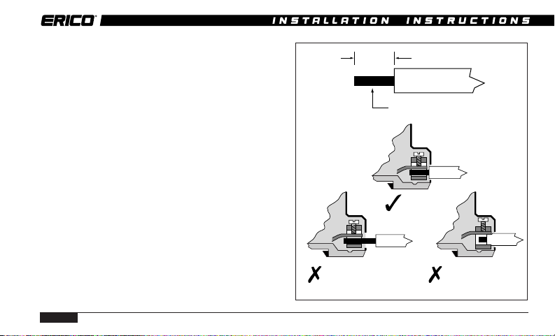
8. CONDUCTOR SIZES
Each Surge Suppressor terminal is designed
to accept wire sizes from 1.5mm2to 6mm2,
solid or stranded conductor. Insulation should
be stripped back 8mm before terminating into
the tunnel terminal.
Where two conductors require termination in
the same tunnel terminal, conductors should
be limited to a maximum size of 4mm2.
Do not use excessive force when tightening the
terminal.
Correct
Insulation cut
back too far
Insulation not cut
back far enough
8mm
1.5-6 mm2conductor

PAGE 11
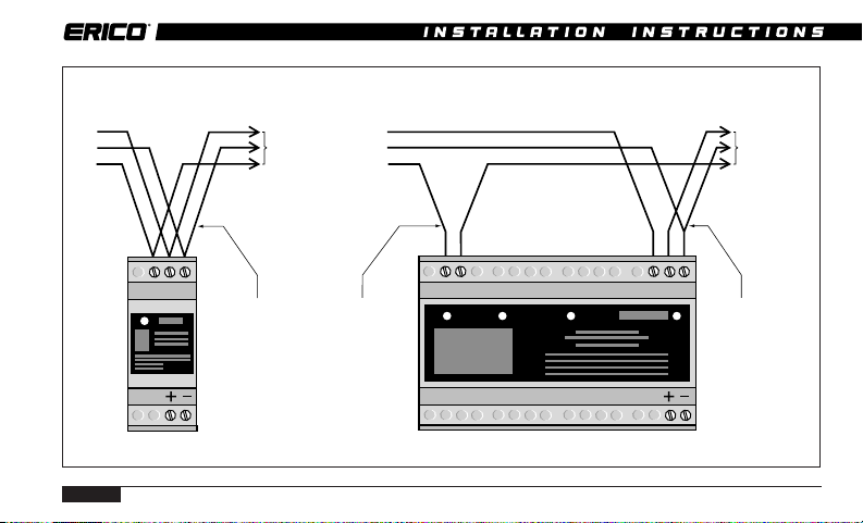
9 CONDUCTOR LENGTH
To optimise transient performance, attempt to
connect units in the “Preferred” fashion as
depicted on pages 11 and 12. Some units have
double terminals to facilitate this. Take care
not to run parallel “protected” and
“unprotected” wiring.
Where this is not possible due to layout or
conductor sizing, use the “Non-preferred” “T”
connection method as depicted on page 13. With
this connection method, the “T” lead length
should be kept as short as practicable (less than
100mm) and wires should be bundled together.
The “T” conductor should be equal in size to the
main conductor, up to a maximum of 6mm
2
.
PREFERRED CONNECTION METHOD
Ph Ph Ph
Ph Ph
Ph
INCORRECT
CORRECT
Separate wires
NON-PREFERRED CONNECTION METHOD
T1 T2
INCORRECT
CORRECT
Keep
Short
Keep Close
T1 T2
PAGE 12
DSD INSTALLATION INSTRUCTIONS
TDS1160-8S
Protected
Equipment
Maximum
conductor
size 4mm2
Maximum
conductor
size 2x4 mm2
or 1x6 mm2
Maximum
conductor
size 6mm2
PREFERRED CONNECTION METHOD EXAMPLE FOR Ph-E PROTECTION
TD140-2S
T2
T1XX
T1
T1T2
T2
Supply
Ph
N
E
Supply
Ph
N
E
Protected
Equipment

PAGE 13
Keep as short
as practical
Keep as short
as practical
Supply
Ph
N
E
Supply
Ph
N
E
Bundle
together
Bundle
together
Maximum
conductor
size 6mm
2
Maximum
conductor
size 6mm
2
NON-PREFERRED "T" CONNECTION METHOD EXAMPLE FOR Ph-E PROTECTION
TDS1160-8S
TDS 140-2S
Protected
Equipment
Protected
Equipment
T2
T1X T2
T2
T1T1X

PAGE 14
DSD INSTALLATION INSTRUCTIONS
10. RCD, ELCB
Where RCDs/ELCBs (Residual Current
Devices / Earth Leakage Circuit Breakers) are
fitted the Surge Suppressor units should be
installed in the circuit prior to these devices
(ie upstream). Where this can not be avoided
and RCDs/ELCBs are installed upstream,
nuisance tripping of the RCD/ELCB may occur
during transient activity.
Contact your local representative for advice if
upstream RCDs/ELCBs can not be avoided.
RCD
ELCB
Protected
Equipment
CORRECT
RCD
ELCB
INCORRECT
PhPh

PAGE 15
11. ISOLATION AND FUSING
Overcurrent and short circuit protection must
be provided to protect the Surge Suppressor
and associated wiring if a fault develops. The
overcurrent protection should be installed in
such a manner to also provide a means of
isolating the TDS-DINLINE module from the
mains supply. This is an important safety
consideration and is required in the event that
any future maintenance or testing is needed.
For Surge Suppressors installed in the
“preferred” connection method (page 12),
upstream overcurrent protection should be
installed based on the maximum current
carrying capacity of the conductors.
Australian regulations AS3000-1991, Table B2
specifies the following upstream protection for
the protection of single phase circuits.
Ph Ph Ph
A mm
2
Conductor Size Required Fuse
A mm
2
CB or Fuse Rewirable Fuse
1.5 mm
2
16A 12A
2.5 mm
2
20A 16A
4.0 mm
2
25A 20A
6.0 mm
2
32A 25A
Fuse selection based on maximum current carrying capacity of
conductor. Smaller rated fuse may be selected if required.
CB = Circuit Breaker.
A mm
2

PAGE 16
DSD INSTALLATION INSTRUCTIONS
For Surge Suppressors installed in the “non-
preferred” connection method (page 13),
depending upon the size and fusing in the
main circuit, the “T” connection may require
independent fusing to be installed.
Circuits with upstream protection rated at
greater than 100A must have a 100A HRC
fuse or circuit breaker installed in the T
connection as detailed by the following
diagram.
Warning:
Isolation/fusing installed in the “T” connection
may disconnect the Surge Suppressor from the
circuit/equipment to be protected. The remote
alarm contacts of the ALARM RELAY (TDS-
AR) should be used to detect this occurrence.
Operation of the isolation/fuse will remove the
protection from the circuit.
Ph
A mm2B mm2
Supply Upstream* T-Connection Required
Conductor Protection Size T-Connection
Size Fuse
A mm
2
A fuse rating B mm
2
B fuse rating
1.5 mm
2
16A 1.5 - 6 mm
2
Nil
2.5 mm
2
20A 2.5 - 6 mm
2
Nil
4.0 mm
2
25A 4 - 6 mm
2
Nil
6.0 mm
2
32A 6 mm
2
Nil
>6.0 mm
2
<100A 6 mm
2
Nil**
>6 mm
2
>100A 6 mm
2
100 A**
* Fuse rating A selection based on maximum current carrying capacity of
conductor. Smaller rating fuse may be selected ir required.
** Short circuit protection selection based on I
2
t rating of cable and fuse.
AB
Supply

PAGE 17
The selection of the 100A HRC fuse is not
based on the load carrying capacity of the
main circuit but the “T” connection I2t rating.
The “T” connection under normal conditions
does not carry the load current. Only under
surge or fault conditions does this connection
carry large currents. Under Australian
Standard AS3008.1-1989 it is permissible to
rate the protection for these types of circuits
by the I2t ratings of the cable. For installation
of Surge Suppressor in countries not covered
by these regulations it is recommended that
this practice be followed, unless it conflicts
with the compliance of the local regulations.
12. STATUS INDICATION
A characteristic of all transient and surge
protection devices is that they degrade in
proportion to the magnitude and number of
incident surges to which they have been
subjected. Status indication should be
periodically monitored to determine if
replacement is required.
2S units
These units are identified by the single Status
Indicator provided on the front panel. When
power is applied and full surge capacity is
available the Status Indicator will be
illuminated. Should the indicator fail to
illuminate the Surge Suppressor should be
replaced, as optimum protection is no longer
provided. Note: The Status Indicator will not
operate (regardless of surge capacity) if power
is not available.
4S units
These units are identified by two Status
Indicators which are provided on the front
panel. These Status Indicators monitor

PAGE 18
DSD INSTALLATION INSTRUCTIONS
separate protection segments. Each Status
Indicator is illuminated when power is
available and when full surge capacity is
available by that segment. The Surge
Suppressor should be replaced if either
Status Indicator fails to illuminate. Note: The
Status Indicators will not operate (regardless
of surge capacity) if power is not available.
8S units
These units are identified by four Status
Indicators which operate similar to above. The
Surge Suppressor should be replaced if any
two or more Status Indicators fail to
illuminate.
13. MAINTENANCE & TESTING
Before removing any unit from service
ensure that power to the device is
isolated. Replacement of any Surge
Suppressor should only be undertaken in
accordance with all relevant Electricity
and Safety Standards by suitably
qualified personnel.
TDS-DINLINE units should be inspected
periodically, and also following any periods of
lightning or transient activity. Check the
status indicators and replace if recommended
in Section 12 -STATUS INDICATION.
For high transient exposure sites or those of a
critical operational nature, it is recommended
that the alarm outputs be monitored to
provide an additional warning of reduced
capacity (refer Section 14 - ALARM RELAY-
TDS-AR).

PAGE 19
TDS-DINLINE Surge Suppressor units are
designed for optimum performance under
severe transient activity. To provide this
performance, electronic components in the
unit are encased in a patented proprietary,
shock and thermal absorbent compound.
Units cannot be serviced, they must be
replaced.
Do not attempt to open or tamper with the
units in any way as this may compromise
performance and will void warranty.
Do not “Megger” or perform other types of
electrical tests that apply voltages greater
than the nominal operating voltage of the
Surge Suppressor. The Suppressor will
attempt to limit these voltages thereby
affecting the test result. Where these tests
must be performed, remove the Surge
Suppressor from circuit first.
14. ALARM RELAY (TDS-AR)
The Surge Suppressor status monitoring
circuit which provides the visual status
display also provides a low voltage opto-
coupler alarm output circuit. This should only
be connected to the TDS ALARM RELAY. The
TDS-AR voltage free alarm contacts may then
provide output to external alarm systems or
remote monitoring circuits.
The TDS ALARM RELAY provides fully
isolated potential free change-over alarm
output contacts. One TDS-AR can be used per
Suppressor opto-coupler alarm or Multiple
Suppressor opto-coupler alarms can be
connected in series to the one TDS-AR to
provide a common output.

PAGE 20
DSD INSTALLATION INSTRUCTIONS
1 x TDS-AR supports:
20 x TDS140-2S
or 10 x TDS 180-4S
or 5 x TDS 1160-8S
or relative combinations.
It is recommended that the TDS-AR unit be
powered from the same power circuit that
feeds to the Surge Suppressor being
monitored, however it can be powered from
other circuits. This allows for example, one
TDS-AR unit to be connected to separate
Surge Suppressors that are protecting a three
phase circuit.
To satisfy Australian wiring regulations the
phase supply to the TDS-AR needs to be
protected by an overcurrent fuse/circuit
breaker. The overcurrent protection should be
selected according to the wiring size
connecting to the TDS-AR Phase and Neutral
terminals. For reference a table of values is
given on page 24.
Note. Depending upon the usage of the TDS-
AR output contacts, failure of power to the
TDS-AR may be interpreted as a failure of one
or more Surge Suppressors. Visual inspection
of all units Status displays would determine
this.
Table of contents
Other ERICO Surge Protector manuals


 4300-PM Specification sheet")

