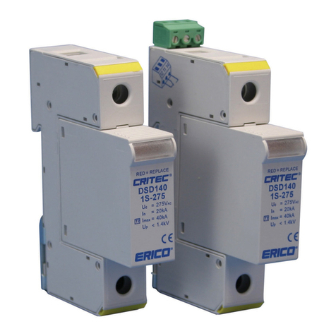
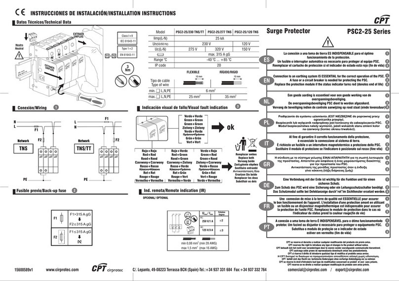
ERICO Pentair TDS Series User manual

1. Preparation
Danger:
Electrical shock or burn hazard. Qualified
personnel should only install this product. Failure to lockout
electrical power during installation or maintenance can
result in fatal electrocution or severe burns. Before making
any connections to this electrical panel please ensure that
power has been removed from all associated wiring,
electrical panels, and other electrical equipment.
Caution Notes:
1. The installation of this Transient Discriminating Surge
Diverter (TDS) should follow all applicable national electrical
codes.
2. Check to ensure that the power frequency line voltage
does not exceed the maximum continuous operating
voltage (Uc) of the TDS.
3. Prior to installation, ensure that the TDS is of the correct
voltage, current, and frequency.
4. The ground (earth) terminal must be connected to a low
impedance earth (<10 ohms) for correct operation.
5. Do not perform a “Flash Test” or use a Megger to test
circuits that are protected with these TDS units. This may
damage the TDS(s) and affect the insulation readings being
performed.
6. Follow all instructions to ensure correct and safe
operation and observe nationally recognized codes of
authorities having jurisdiction.
7. Do not attempt to open or tamper with the TDS unit in
any way as this may compromise performance and will void
warranty.
2. Introduction
The Transient Discriminating Surge Diverter (TDS) series has
been designed to provide one mode of protection to single-phase
power distribution systems (TDS150 or TDS1100), multi-modes in
a split phase distribution system (TDS50) or in a three-phase
distribution system (TDS350).
Units can be connected (L-N), (L-G) or (N-G) depending on the
type of power distribution system.
Multiple TDS units can be used to provide multi-modes of
protection or to protect three-phase distribution systems.
TDS units are available with maximum continuous operating
voltages (Uc) of: 170V, 275V, 320V and 610V for the protection of
distribution systems with nominal RMS voltages of 120Vac,
220Vac, 240Vac and 480Vac, respectively. TDS units may also be
used to protect DC power systems - ref. Table 1.
3. Quick Installation Overview
Please follow the sequence indicated:
1. First, ensure that power is removed from the area and the
circuits to be connected.
2. Install earth leakage protection (RCD) if appropriate or where
required by national codes and authorities having jurisdiction.
Note: When connecting surge protection L-G it is preferable to
install the device before the RCD to avoid “nuisance tripping”
which may occur when the SPD operates.
3. Connect wiring to the two primary terminals indicated.
4. Connect the alarm terminals if remote monitoring is required.
5. Apply power and observe correct operation of the TDS and
status indication is not tripped.
4. Mounting
TDS’s are designed to clip to 35mm (top hat) DIN rails (standard
EN50022) set in the horizontal position with the TDS securing clips
towards the bottom of the rail and the label text facing the correct
way up.
Note:
TDS modules must be installed in an enclosure or switch
board panel in such a way that :
DANGER
ELECTRICAL SHOCK OR BURN HAZARD. HAZARDOUS VOLTAGES EXIST INTERNAL TO THE TDS. THIS UNIT SHOULD BE INSTALLED AND SERVICED ONLY BY
QUALIFIED PERSONNEL IN CONFORMANCE WITH ALL GOVERNING CODES AND INSTRUCTIONS. FAILURE TO LOCKOUT ELECTRICAL POWER DURING INSTALLATION
OR MAINTENANCE CAN RESULT IN FATAL ELECTROCUTION, SEVERE BURNS, OR OTHER INJURIES. BEFORE WORKING WITH OR MAKING ANY CONNECTIONS TO THIS
DEVICE, BE SURE THAT POWER HAS BEEN REMOVED FROM ALL ASSOCIATED WIRING, ELECTRICAL PANELS, AND OTHER ELECTRICAL EQUIPMENT.
1. The power supply to the TDS should always be turned (and locked) OFF before the unit is accessed for any reason.
2. Prior to installation, ensure that the TDS is of the correct voltage, current, phasing, and frequency for the applicable rating of the power distribution system.
3. This unit must be installed on the load side of the main over-current protection.
4. Diagrams are for reference only. Schematics are representative of typical applications and are only to be used for reference.
Product Series
TDS150-1SR-xxx
TDS1100-1SR-xxx
TDS350-xxx-xxx
TDS50 120/240
TECHNICAL SUPPORT
www.erico.pentair.com
IPCR1502_A
1 OF 2
INSTRUCTION SHEET
Pentair, CADDY, ERICO CADWELD, ERICO CRITEC, ERICO, ERIFLEX, and LENTON are owned by Pentair or its global affiliates. All other trademarks are
the property of their respective owners. Pentair reserves the right to change specifications without prior notice.
WARNING:
Pentair products shall be installed and used only as indicated in Pentair product instruction sheets and training materials. Instruction sheets are available at
1.
www.erico.pentair.com
and from your Pentair customer service representative.
Pentair products must never be used for a purpose other than the purpose for which they were designed or in a manner that exceeds specified load ratings.
2.
All instructions must be
completely
followed to ensure proper and safe installation and performance.
3.
Improper installation, misuse, misapplication or other failure to completely follow Pentair's instructions and warnings may cause product malfunction, property
4.
damage, serious bodily injury and/or death, and void your warranty.
SAFETY INSTRUCTIONS:
All governing codes and regulations and those required by the job site must be observed.
Always use appropriate safety equipment such as eye protection, hard hat, and gloves as appropriate to the application.
TDS Series
© 2005-2017 Pentair All Rights Reserved

The location of this enclosure prevents the temperature of the
TDS unit(s) from exceeding its maximum specified rating.
Adequate electrical and safety protection is provided by the
enclosure to all exposed terminals.
The location and type of enclosure meets the specified
environmental requirements and prevents the ingress of moisture
and water.
The indicator status of the TDS can be readily inspected.
5. Electrical Connection
When connecting the TDS on the input side of the distribution
panel wiring, it is usual to wire the TDS L-N (L1, L2, L3 to N on 3
phase systems). When connecting the TDS to the output side of
the panel wiring, it is usual to wire it L-PE/PEN.
On TN-C networks, three TDS units are required. L1, L2, L3
should be protected to PEN.
On TN-S networks, four TDS units are required. L1, L2, L3
should be protected to N, and N should be protected to PE.
On TT networks, three TDS units and a SGD unit are required.
L1, L2, L3 should be protected to N using the TDS units, and N
should be protected to PE using the SGD unit.
On IT networks, four TDS units are required. L1, L2, L3, N
should be protected to PE using 440V TDS units on a normal
230V system.
On the TDS1100 series, a “Kelvin” type connection can be
made using separate input and output terminal pairs. This
configuration helps reduce the effects of lead length. The
maximum load current under such a configuration should be
limited to 125A.
6. Wiring
The interconnecting wiring should:
Be as short as possible - not exceeding 300mm (12”).
Avoid sharp bends >100mm radius is recommended.
Have the conductors twisted together where possible.
Terminals will allow connection of 25mm² (#4AWG) multi-
strand wiring or 35mm² (#2AWG) solid - ref. Table 1. The wire
insulation should be stripped back 8mm (5/16").
7. Residual Current Detectors (RCD)
When an RCD is used, it is preferable that the TDS modules be
installed prior to (upstream of) this device to avoid nuisance
tripping which may occur during transient activity.
8. Fusing and Isolation
Overcurrent protection must be installed in the upstream circuit of
every TDS unit if the mains supply is > 100A. This is to provide
protection to the TDS, the load and the wiring in the case of a fault
- ref. Table 1 for suitable fuse ratings.
Note:
Operation of this over-current protection under excessive
surge conditions may occur removing protection from the circuit.
The Remote Status contacts should be monitored for this
possibility.
9. Status Indication
TDS modules incorporate an internal thermal disconnect element,
which automatically disconnects the varistor from the network in
the event of a thermal overload. Should the internal disconnect
operate, a red flag appears in the transparent window of the
status indicator(s) on the front of the TDS.
10. Maintenance and Testing
Before removing a TDS module from service,
ensure that the power has been removed and if
possible “locked out”. Qualified personnel should
only undertake replacement of TDS modules.
Replacement plug-in modules are available.
Note:
It is very important to ensure that the new
module is of the same type and voltage as that
being replaced.
Note:
TDS units should be inspected periodically,
and also following any periods of lightning or
transient voltage activity. Check the Status Indicator
and replace the module if required.
11. Remote Status
The TDS provides remote status monitoring via
voltage-free contacts. Failure of the TDS is signified
by the N/C contacts (11,14) opening and the N/O
contacts (11,12) closing. Ensure that the voltage
and current ratings of the contacts are not
exceeded.
Note:
The TDS contacts are independent of
whether power is supplied, or not, to the TDS
module. The status of the contacts is given solely
by the failure status of the TDS module.
Table 1. TDS operating specifications
TECHNICAL SUPPORT
www.erico.pentair.com
IPCR1502_A
2 OF 2
INSTRUCTION SHEET
Pentair, CADDY, ERICO CADWELD, ERICO CRITEC, ERICO, ERIFLEX, and LENTON are owned by Pentair or its global affiliates. All other trademarks are
the property of their respective owners. Pentair reserves the right to change specifications without prior notice.
© 2005-2017 Pentair All Rights Reserved
This manual suits for next models
5
Other ERICO Surge Protector manuals
Popular Surge Protector manuals by other brands
socomec
socomec SURGYS D40 quick start guide

Progressive Industries
Progressive Industries SSP-50 operating instructions
OEZ
OEZ SJB-25E-3-MZS Instructions for use
M-system
M-system MDP-RB instruction manual
Liebert
Liebert PowerSure PST quick start guide
Rocket Fish
Rocket Fish RF-PCS12ES13 Guía De Instalación Rápida

Monster Power
Monster Power HDP 1250G+ Instructions and warranty information
Radio Shack
Radio Shack Surge Protector owner's manual
OBO Bettermann
OBO Bettermann FLD2 Series Installation instruction
Siemens
Siemens 3EL2 operating instructions
Sven
Sven AVR SLIM-500 LCD Operation manual

Mersen
Mersen Surge-Trap instructions
