Eridan IP535-07ea-RS User manual

12 Lenina St., Berezovski,
Sverdlovsk Region, 623700, Russia
Tel./fax: +7 (343) 351-05-07 (multichannel)
ОКПД2: 26.30.50.121
Explosion-Proof Addressable Manual Fire
CALL POINT
IP535-07ea-RS
(Modbus RTU protocol)
Operation Manual
4371-006-43082497-04-04 РЭ, 2021
EXPLOSION-PROOF FIRE EQUIPMENT
IP535-07ea-RS 4371-006-43082497-04-04 РЭ Rev. No.18 dd. 17.12.2019

2
1. APPLICATION OF THE PRODUCT
This Operation manual (OM) covers the explosion-proof fire manual call point IP535-07e in
IP535-07ea-RS modification - explosion-proof addressable manual fire call point with support of
ModBus RTU protocol (further –the call point, the product).
The call point is designed for generation of fire alarm signal or launch of fire extinguishment by
means of pulling out the driving element in explosive areas or general industrial purpose areas.
The call point can be used in fire alarm and fire-extinguishing systems for generation and
sending of electric alarm signals to fire alarm control panels (FACP) or in automatic process
control systems for transferring of digital data signal via standard communication channel RS-485
with Modbus RTU protocol.
The call point can be operated in varied climatic areas (NF1, F1, MU1, etc.) within temperature
range from -60°С to +85°С, placement category 1, atmosphere type II or III as per GOST 15150-
69, protection degree of the call point's casing against dust and water corresponds to IP66/IР67 as
per GOST 14254-96 (IEC 60529:2013).
The call point meets the safety requirements for explosion-proof equipment as per TR CU
012/2011 and Technical Regulation on Fire Safety Requirements TR EAEU 043/2017.
The call point has explosion-proof protection level, explosion-proof protection type ‘explosion
proof casing ‘d’ and explosion proofness marking as per GOST 31610.0-2014 (IEC 60079-0:2011):
1Ex db IIC T6 Gb
Ex tb IIIС Т85°C Db
The explosion-proof manual fire call point must be used with cable glands and plugs of the
manufacturer or other certified cable glands and plugs that provide explosion protection type
‘explosion-proof enclosure’ and explosion protection level 1. The protection degree (IP) and the
operating temperature range of cable glands should correspond to the operating conditions of the
call point.
The call point can be installed in class 1 and 2 indoor explosive areas and outdoor installations
according to the assigned explosion proofness marking, TR CU 012/2011, GOST IEC 60079-14-
2013, the Classification of Chapter 7.3 of the Electrical Installation Code (version 6) and other
regulations setting forth application of electrical equipment in explosive areas.
The environment may contain explosive mixes of gases and vapors with air, groups IIA, IIB
and IIC as per GOST IEC 60079-10-1-2013, GOST R IEC 60079-20-1-2011 as well as combustible
dusts, groups IIIA, IIIB and IIIC as per GOST IEC 60079-10-2-2011.
The call point can be manufactured in the following modifications:
a) addressable call point IP535-07ea-RS-A in explosion-proof version designed as a class A
call point as per GOST R 53325-2012
b) addressable call point IP535-07ea-RS-B in explosion-proof version designed as a class B
call point as per GOST R 53325-2012
c) addressable remote start device IP535-07ea-RS-START in explosion-proof version
designed as a class B call point as per GOST R 53325-2012.
Production of the call points is only possible subject to availability of valid certificates of
compliance with fire safety and equipment explosion proofness requirements.
The call points designed for operation on vessels classified by the Russian Maritime Register of
Shipbuilding (further –the RS) must be manufactured and tested under technical supervision of the
RS. The need for such supervision must be specified when placing the order.
The call points IP535-07ea-RS are not measuring devices.
Connection diagrams of the call point are shown in Annex B.
The call point supports operation via Modbus RTU protocol in driven mode and meets the
requirements of the following specifications:
1) MODBUS Application Protocol Specification V1.1b3

3
2) MODBUS over Serial Line Specification and Implementation Guide V1.02.
Description of Modbus RTU exchange protocol for the addressable call point IP535-07ea-RS is
provided in Annex B.
When placing an order and drafting accounting source documents, the description of the call
point IP535-07ea-RS must consist as a minimum of its short name, reference designation and
number of units.
The short name must be as follows: ‘Explosion-proof addressable manual call point’ or
‘Explosion-proof addressable remote start device’.
In technical documents, the description of the call point IP535-07ea-RS must consist of its
name, reference designation and designation of TU.
The structure of the reference designation of the IP535-07ea-RS must contain the following:
IP535-07e
X2
-Х3
-Х4
/Х5
(Х6)/
Х7
, Х8
, Х9
, Х10
[ 1 ]
[ 2 ]
[ 3 ]
[ 4 ]
[ 5 ]
[ 6 ]
[ 7 ]
[ 8 ]
[ 9 ]
[ 10 ]
[ 1 ] Name of the series of the call point.
[ 2 ] Х2 - designation according to address setting type and the interface and protocol supported:
–a-RS - addressable call point designed for sending of digital data signals via standard
communication channel RS-485 with Modbus RTU protocol.
[ 3 ] X3 - designation of the device modification according to its intended application:
–none - manual call point
–START - remote start device (UDP).
[ 4 ] X4 - designation of the version variant
for the IP535-07ea-RS call point - call point class as per GOST R 53325-2012:
–A - class A - one-step activation
–B - class B - activation by performing several actions.
for the IP535-07ea-RS-START start device:
–not applicable.
[ 5 ] X5 - intended use of the UDP IP535-07ea-RS-START (not indicated in case of manual fire
call points):
–LAUNCH OF FIRE SUPPRESSION - launch of automatic fire fighting system of gaseous
fire suppression (color: yellow) - by default, it can be omitted
–LAUNCH OF SMOKE REMOVAL - launch of smoke removal systems (color: orange)
–EMERGENCY EXIT - generation of emergency signals or signals of emergency exit
unlocking (color: green)
–EMERGENCY SHUTDOWN - shutdown of automatic fire fighting system of gaseous fire
suppression (color: blue)
–START - intended use of the UDP is defined by the user (color: grey).
[ 6 ] X6 - UDP body color (not indicated in case of manual fire call points):
–Zh - yellow
–O - orange
–Z - green
–S - blue
–SR - grey.
* By agreement with Eridan JSC, UDP can be manufactured with any application text on the
nameplate on the cover and the body made in any color (except for red).
[ 7 ] X7 - additional design alphanumeric designation (design protection, by agreement with the
customer).
[ 8 ] Х8 - availability of certificate of type approval of the RMRS:
–no - without certificate
–RMRS - availability of certificate of type approval of the RMRS.
[ 9 ] Х9 - fitting with cable glands (as per clause 3 hereof).

4
[ 10 ] Х10 - fitting with additional equipment:
–SZK IP535 - protective visor
–other equipment (designation by agreement with the customer).
Omission or alteration of the data sequence [5-10] in designation of the product is allowed as
well as insertion of other punctuation marks between the data that does not lead to a different
interpretation of the product version.
Examples of reference designation of the IP535-07ea-RS call point:
‘IP535-07ea-RS-A, KVO14, KVO14, SZK IP535’
‘IP535-07ea-RS-START LAUNCH OF FIRE SUPPRESSION (ZH)/ KVM15, ZG’.
Examples of the IP535-07ea-RS call point description when ordering:
‘Explosion-proof addressable manual call point IP535-07ea-RS-A, KVO14, KVO14, SZK
IP535 - 2 units’
‘Explosion-proof remote start device IP535-07ea-RS-START/LAUNCH OF FIRE
SUPPRESSION (ZH)/ KVM15, ZG’.
Examples of the IP535-07ea-RS call point description when drafting documents:
‘Explosion-proof addressable fire manual call point IP535-07ea-RS-A, KVO14, KVO14, SZK
IP535, TU 4371-006-43082497-04’
‘Explosion-proof addressable remote start device IP535-07ea-RS-START/LAUNCH OF FIRE
SUPPRESSION (ZH)/ KVM15, ZG, TU 4371-006-43082497-04’.
2. TECHNICAL DATA
2.1. Pursuant to GOST R 53325-2012, the call point IP535-07ea-RS is an A or B class fire
manual call point (depending on the version), the device IP535-07ea-RS-START is a class B fire
manual call point.
2.2. Power supply and data exchange of the call point are provided via the four-wire
communication line: 2 wires - RS-485 line, Modbus RTU protocol, 2 wires - electrical power
supply.
The call points must be connected to communication line in parallel, with strict observation of
polarity.
2.3. Maximum number of addressable devices to be connected: 32.
2.4. The call point is energized from a direct current source with a rated voltage of 24 V
±10%. The call point remains operational within the range of supply voltages from 8 V to 28 V.
2.5. Maximum current consumption value: 20 mA.
2.6. Maximum warm-up time of the call point after powering up is 1 sec.
2.7. In accordance with clause 4.2.1.10 of GOST R 53325-2012 resetting of the call point
from ‘Activated’ mode to standby mode is possible only when the driving element is installed after
receiving a ‘Device reboot’ or ‘Registered events reset’ command from the control device (in case
the ‘Activation registration’ function is activated, register 50; see Annex B) or when the call point
is powered down.
In case the ‘Activation registration’ function is deactivated, the minimum time of fixation in
‘Activated’ mode is 10 sec.
In order to comply with GOST R 53325-2012 and when operating the call point in the territory
of Russia, the ‘Activation registration’ function must be activated.
2.8. Optron relays status in standby mode by default:
–Р1 (notification ‘Activated’) normally-open (NO)
–R2 (notification ‘Fault’) normally-closed (NC).
The relays are programmable, for configuration of the initial relay status in register 50, see
Annex B.
2.9. Optron keys parameters:
–maximum switching current 100 mA

5
–maximum switching voltage 60 V
–maximum closed key resistance 16 Ohm
–minimum open key resistance 15 MOhm
–input/output galvanic separation voltage 1,500 V.
2.10. The call points include a two-colored (green/red) LED indicator of operation modes.
2.11. Maximum overall dimensions of the call point (without cable glands): 120x135x110 mm.
2.12. Maximum weight of the call point (without cable glands): 1.0 kg.
Maximum gross weight of 1 unit in an individual package: 1.3 kg.
Maximum weight of a four-unit packaging: 0.3 kg; eight-unit packaging: 0.6 kg.
2.13. Reliability indexes:
–the call point is designed for 24/7 round-o'clock continuous operation
–minimum mean time between failures in standby mode is 60,000 hours
–the minimum specified lifetime is 10 years.
The specified ratings can be extended subject to implementation of actions in accordance with
GOST 33272-2015, works as per par. 10.4 hereof and a positive conclusion based on results of the
actions implemented.
In case decision is made of their decommissioning and withdrawal, the call points must be
disposed of by the end user.
2.14. Operating conditions:
–ambient air temperature from minus 60°C to plus 85°C
–atmospheric pressure from 84 to 106.7 kPa (from 630 to 800 mm Hg)
–relative air humidity 100% at a maximum temperature of 25°C and 95% without
condensation at a maximum temperature of 40°C.
2.15. Electric shock hazard protection of the call point corresponds to Class III as per GOST
12.2.007.0-75.
2.16. Electric insulation between the connected output conductors and the call point body under
normal climatic conditions withstands a sinusoidal alternating voltage of 0.55 kV, 50 Hz during one
minute.
2.17. Electrical resistance of insulation between the connected output conductors and the call
point body under normal climatic conditions is minimum 20 MOhm.
2.18. The call point is resistant to sinusoidal vibration of 2-150 Hz under acceleration of up to
0.7g.
2.19. The call point remains operational when subjected to direct mechanical impact of 1.9 J.
2.20. The call point is resistant to mechanical impacts under acceleration of 5g and length of
impact pulse of 18±5 msec.
2.21. The call point design guarantees its reliability under seismic impact of 9 on the MSK-64
scale as per GOST 30546.1-98.
2.22. The structural design of the call points guarantees their fire safety as per GOST R 53325-
2012 under normal operation and operation in fault condition.
2.23. The call points comply with the regulations and requirements of electromagnetic
compatibility as per TR CU 020/2011, GOST R 53325-2012, test rigidity degree 2.
Value of radio-noise field intensity generated by the call point during its operation does not
exceed limits established as per GOST R 53325-2012 for Class B equipment.
2.24. Ship service call points are resistant to salt (sea) fog and failure-proof in case of long
heeling of the ship up to 22.5°, max. hull angle 10°, at simultaneous heeling and hull angle as
above, as well as at rolling up to 22.5° every 7-9 sec and at pitching up to 10° from the vertical
axis.
2.25. The input device of the call point is designed to be wired with round cable section, outer
diameter 6-12 mm (along the rubber sealing, i.e. cable wrapping).
Upon customer request, the call points are provided with input devices or plugs can be installed.
6
The connection thread for cable glands installation is metric, М20х1.5 mm.
2.26. Cables must be selected in accordance with SP 6.13130.2013 and GOST IEC 60079-14-
2013, minimum wire section: 0.75 mm2, wrapping diameter: 6-12 mm.
In case the call point is operated under heavy electromagnetic interference conditions and in
case the communication line is very long, please use ‘twisted pair’ type shielded cable with one-
side earthing of the shield, near the control device.
2.27. The terminals of the call point allow clamping single wires or strand wires with a cross-
section of 0.08-2.5 mm2(28-14 AWG).
2.28. The call points must be located on site according to the requirements of SP
484.1311500.2020.
2.29. Recommended position of the call point: with the input devices facing down (see figure 1,
Annex A).
3. SCOPE OF SUPPLY
3.1. The call point complete with input devices (upon request)
The explosion-proof manual fire call point must be used with cable glands and plugs of the
manufacturer or other certified cable glands and plugs that provide explosion protection type
‘explosion-proof enclosure’ and explosion protection level 1. The protection degree (IP) and the
operating temperature range of cable glands should correspond to the operating conditions of the
call point.
By agreement with the customer, call points can be equipped with different Eridan-branded
cable glands as well as with plugs.
Legend for ordering:
ShT - pipe union for pipe arrangement with outer thread
KVB - cable gland for armored cable (any armor type) with single seal along the cable
wrapping
KVBU - cable gland for armored cable with double seal along the cable external insulation and
cable wrapping with any armor type
KVO - cable gland for surface cable laying
KVM - cable gland for installation in metal hose
ZG - terminal plug М20х1.5 mm.
Detailed information on furnishing of the call point with input devices is provided in technical
certificate КВ-00.000 ‘Cable glands’.
By agreement with the customer, the product can be equipped with different certified cable
glands.
3.2. General scope of supply of the call point
Table 1.
Designation
Q’ty
Notes
Call point
1
Modification upon request
Cable gland with a set of sealing rings and mounting
washers
-
Upon request
Terminal key WAGO or mounting screwdriver
1
Special wrench
1
Fastener (self-tapping screw)
2
Visor
1
Upon request
Removable element
10
For fixation of the protective
element of IP535-07ea-RS-B or
IP535-07ea-RS-START
Operation Manual
1

7
Technical certificate
1
Information regarding cable glands
1
For multiple package
Certificates and declarations of conformity
1
Per batch
RS certificate
1
Per batch when ordering
4. DESCRIPTION AND MODE OF OPERATION
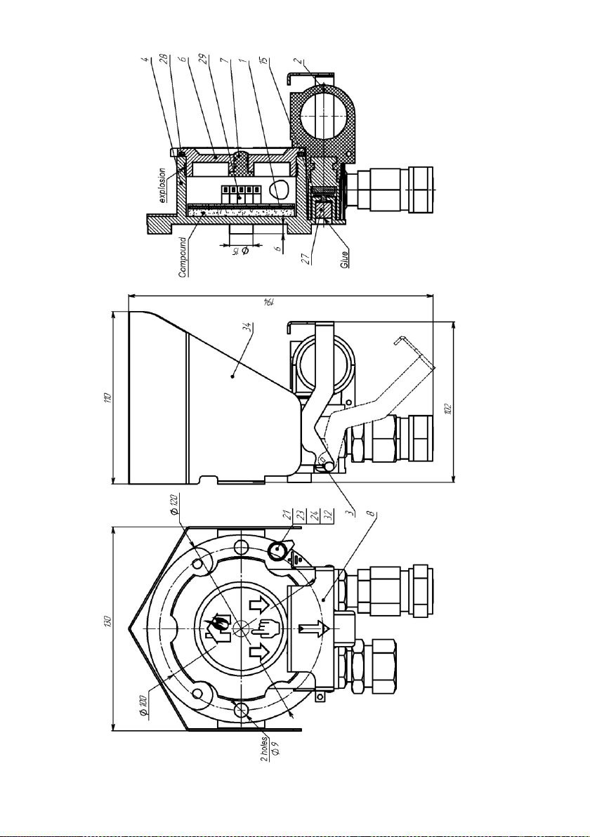
4.1. The call point contains units and parts specified in Figure 1 of Annex A.
The cast body (4) of the call point contains a board (1) with a signal green-and-red LED (29);
the board is filled with insulating compound; the cover (6) with an integrated lens (7) is screwed
into the body and secured against loosening by the driving element (2); the driving element bends
the magnetic field lines in circle (27).
In the call point IP535-07ea-RS-A, after installation of the driving element (2), it is sealed by
lashing via holes in the cover.
In the call point IP535-07ea-RS-B or the start device IP535-07ea-RS-START, the access to the
driving element (2) is protected by means of the element (8) that is fixed by means of installation of
the removable element (3).
Upon request the call point may be equipped with a protective visor (34, option).
The call point is fixed to a vertical surface by means of the body with the cable glands facing
down.
The input device of the call point is designed to be wired with a round section cable, outer
diameter 6-12 mm (along the rubber sealing, i.e., cable wrapping). The call point is fitted with a set
of sealing rings and cable glands (or plugs) for electrical cable sealing. The connection thread for
cable glands installation is М20х1.5 mm.
4.2. Power supply and data exchange of the call point are provided via the four-wire
communication line: 2 wires - RS-485 line, Modbus RTU protocol, 2 wires - electrical power
supply. The call points must be connected to communication line in parallel, with strict observation
of polarity.
Connection diagrams of the call point are shown in Annex B.
In order to configure the call point using a personal computer, Lectus Modbus OPC/DDE server
(ver. 3.9 and above, www.lectussoft.com), Modbus Poll (v.5.0.1 and above,
www.modbustools.com) software or a specialized application ‘Configuration tool IP535-07ea-RS’
(www.eridan.ru) can be used.
Any function of Modbus RTU announced for the call point can be deemed realized if a
corresponding variable can be read/recorded using Lectus Modbus OPC/DDE server (ver. 3.9) or
Modbus Poll (v.5.0.1 and above) software.
The call point provides support of the following operation modes: standby mode, “Activated’
mode, ‘Acknowledgement’ mode, ‘Failure’ mode.
The call point operates in standby mode when the driving element is installed, the activation
signal is reset and there is no failures.
The call point generates ‘Activated’ alarm notification when the driving element is pulled out.
The call point transfers ‘Activated’ message to FACP by means of opening or closing of the relay
R1 contacts (adjustment of the relay off-position is carried out during the device configuring).
When the ‘Activation registration’ function is active, resetting of the call point from ‘Activated’
mode to standby mode is possible only with the driving element installed after receiving a ‘Device
reboot’ or ‘Registered events reset’ command from the control device or when the call point is
powered down. In order to comply with GOST R 53325-2012 and when operating the call point in
the territory of Russia, the ‘Activation registration’ function must be activated.
When ‘Automatic recovery’ mode is activated, reset of the call point from ‘Activated’ mode
can be carried out minimum 10 seconds after such activation.

8
The acknowledgement function (activation acknowledgement issued by the panel) can be
activated in the call point.
The call point generates ‘Fault’ notification in case of automatic detection of a malfunction.
The call point transfers ‘Failure’ message to FACP by means of opening of the relay R2 contacts.
When operating with a top level controller, the call point uses the serial interface RS-485
(Modbus protocol, transfer mode RTU) for transfer of data related to its condition and other service
data. The call point supports operation via Modbus RTU protocol in driven device mode.
Description of Modbus RTU exchange protocol in provided in Annex B.
4.3. The call point is equipped with a bicolor LED indicator (29) providing data on the call
point status.
Operation modes of the call point optic indicator are indicated in table 2 below.
4.4. In order to activate the addressable call point IP535-07ea-RS (addressable remote start
device IP535-07ea-RS-START):
–connect the call point (device) to the power supply source and the RS-485 communication
line. If necessary, connect the actuating relays R1 and R2 of the call point (device). Operation of
the call point (device) should be controlled by means of operation of its internal indicator, relay
condition as well as its own status displayed in register 10 (see Annex B)
–pull out the driving element (for the IP535-07ea-RS-B or IP535-07ea-RS-START, shift the
protective element (8) thus breaking the removable element (3) and giving access to the driving
element (2), then pull out the driving element)
–this will cause the instrument to receive the ‘Activated’ signal from the call point (device);
it will display the corresponding message and will send back to the call point an acknowledgement
of successful signal receiving (if the acknowledgement function is active). Upon receiving of the
acknowledgement signal by the call point (device), its transition from standby mode to ‘Activated’
mode will be indicated by the red signal LED of the call point (device); the actuating relay R1 will
change its status
–return the driving element (2) to the initial position (for the IP535-07ea-RS-B or IP535-
07ea-RS-START, return the driving element (2) to the initial position; install the protective element
(8) fixing it with the removable element (3) from the scope of supply)
–the method of returning the call point from ‘Activated’ mode back to standby mode will
depend on the value of bit 0 ‘Activation registration’ in register 50 (see Annex B).
Table 2.
Indicator
Indicator operation mode
Operation time
Device operation mode
green
red
◌
◌
Green and red fast flashing
(at the same time)
Period: 0.5 s, glow time 0.25
s
Device start up and self-
diagnostics
◌
-
Green rare flashing
(independently from the red
indicator)
Period: 5 s, glow time 0.3 s
No exchange via RS-485
◌
-
Green fast flashing
(independently from the red
indicator)
Period: 1 s, glow time 0.3 s
Exchange via RS-485 in
progress
◌
○
The green is flashing, the red
is off
Rare green flashing with a 5
s or 1 s interval and glow
time of 0.3 s, the red is off
‘Norm’ mode, exchange
or no exchange via RS-
485
◌
-
-
◌
Alternative green and red
flashing
Green: period - 5 s, glow
time 0.3 s
red: period - 1 s, glow time
0.3 s
‘Acknowledgement’
mode, no exchange via
RS-485
Period - 1 s, green and red
glow time 0.3 s
‘Acknowledgement’
mode, exchange via RS-

9
485
-
●
Constant red glow
(independently of the green
indicator)
Constant glow
‘Activated’ operation
mode
●
●
Green and red constant glow
Constant glow
A failure has been
registered
5. PROVISIONS FOR EXPLOSION PROOFNESS
5.1. In terms of explosion protection, the explosion-proof call point IP535-07ea-RS meets the
requirements of TR CU 012/2011, GOST 31610.0-2014 (IEC 60079-0:2011), GOST IEC 60079-1-
2013, GOST IEC 60079-31-2013.
5.2. The assembled call point with installed cable glands is an explosion-proof enclosure that
meets the requirements of GOST 31610.0-2014 (IEC 60079-0:2011) for electrical equipment of
groups II and III with high level of mechanical damage hazard. The call point casing has protection
IP66/IP67 as per GOST 14254-2015 (IEC 60529:2013).
5.3. Explosion-resistance of the call point is achieved by means of application of explosion
resistant threaded and sealed connections as per GOST IEC 60079-1-2013.
Strength of each casing is checked during manufacturing via hydraulic tests by 1.5x explosion
pressure during the time necessary for inspection but not less than 10 seconds.
5.4. Dust ignition protection is provided by means of application of ‘protection from dust
ignition by means of ‘t’ enclosures’. The parameters of connections of the casing elements comply
with the requirements of GOST IEC 60079-31-2013.
5.5. Cable glands ensure strong and stable sealing of cables. Sealing elements and plugs meet
the requirements for explosion proofness as per GOST IEC 60079-1-2013.
5.6. The explosion-proof manual fire call point must be used with cable glands and plugs of
the manufacturer or other certified cable glands and plugs that provide explosion protection type
‘explosion-proof enclosure’ and explosion protection level 1. The protection degree (IP) and the
operating temperature range of cable glands should correspond to the operating conditions of the
call point.
5.7. Composition of the materials used for call point production provides its frictional intrinsic
safety and meets the requirements of GOST 31610.0-2014 (IEC 60079-0:2011).
5.8. The maximum heating temperature of outer surface of the call point enclosure under
normal and emergency conditions does not exceed the values admissible for electrical systems of
the temperature classes Т6 as per GOST 31610.0-2014 (IEC 60079-0:2011).
5.9. On the call point's body there is a nameplate indicating explosion proofness markings,
and on the cover, there is a warning ‘Unplug before opening’.
5.10. Explosion-proof surfaces of the cover and the body are covered with anti-corrosion heat
resistant grease as per GOST 9433-80.
5.11. The spring washer prevents the grounding clamp from loosening.
5.12. Sealed lashing on the driving element prevents the cover of the explosion-proof casing
from self-unscrewing (to be installed by the customer).
6. PROVISIONS FOR EXPLOSION PROOFNESS DURING INSTALLATION
6.1. Conditions of operation and installation of the call point must meet the provisions set
forth in TR CU 012/2011, GOST IEC 60079-14-2013, Chapter 7.3 of the EIC (version 6),
Regulations for operation of consumer electrical installations, Chapter 3.4, safety regulations and
any other regulations as may be effective in the industry where the call point is applied.
6.2. The call points must be used in accordance with the established explosion proofness
marking. Possible explosive areas of application, categories and groups of explosive gas, vapor and
air mixes are in accordance with the requirements of GOST IEC 60079-10-1-2013 and Chapter 7.3

10
of the Electrical Installation Code (version 6). The possible explosive areas of dust atmospheres of
the call point application are in accordance with the requirements of GOST IEC 60079-10-2-2013.
6.3. Before mounting the call point, its visual inspection is necessary. Please check if the
casing is intact, and also check availability of the following: sealing elements of the cable glands
and the cover, explosion proofness marking and the warning ‘Unplug before opening’.
6.4. No dents, mechanical damage and corrosion are allowed on explosion-proof surfaces of
units and parts to be disassembled.
6.5. Power supply to the call point must be arranged in strict compliance with the effective
Manual for installation of the equipment of power supply and lighting circuits in explosive areas
VSN 332-74 and with this Operation Manual.
6.6. In explosive areas, use of cables with polyethylene insulation or sheath is not allowed.
6.7. Installation works must be carried out when power supply lines are disconnected. The
electrical connection diagram must comply with the Figures of Annex B.
6.8. The call point body must be grounded by means of a copper wire with min. 1.5 mm
diameter. The grounding wire must have a reliable contact with the body and the grounding circuit.
6.9. Sealing of cable in the input device socket must be performed with extreme care, since
explosion proofness of the input device depends on that.
6.10. In case one input device only is used in the call point, vacant input device must be
plugged securely by means of the plug (Figure 2e, Annex A).
6.11. Anti-corrosion heat resistant grease as per GOST 9433-80 must be restored on explosion-
proof surfaces of the cover and the body.
6.12. The call point must be sealed after installation.
7. SAFETY PROVISIONS
7.1. Compliance with the safety rules is mandatory for safe operation and use of the call
points.
7.2. Any works related to installation, inspection, maintenance and operation of the call points
must be only permitted to persons that have undergone the professional and safety trainings,
certification by the certifying board and have been acquainted with this operation manual.
7.3. Any works related to maintenance of the call point in explosive area that involve opening
of its cover must be carried out after powering down the device.
7.4. The call points are safe for the personnel during installation, repairs and routine work
both in good condition and in case of any possible malfunctions.
7.5. Electric shock hazard protection of the call point corresponds to Class III as per GOST
12.2.007.0-75.
7.6. Operators are responsible for work safety.
8. PROCEDURE OF INSTALLATION AND OPERATION
8.1. After receiving the call point, prepare the place of its operation, open the package, check
the scope of supply according to clause 3 of the technical certificate and the packing list. If the call
point was subjected to negative temperatures before opening the package, keep it at room
temperature for minimum four hours.
8.2. Carry out visual inspection of the call point; make sure there are no visible mechanical
damages, and the explosion marking is available.
8.3. Check the call point’s functionality, in order to do that:
a) Establish the check circuit in accordance with Annex B in order to check the addressable
call point functionality. If necessary, connect the actuating relays R1 and R2 of the call point.
Exchange check software, for example, Lectus Modbus OPC/DDE server (v. 3.9 and above) or
Modbus Poll (v.5.0.1 and above), must be installed on the PC.
b) Apply voltage to the call point.

11
c) Wait for one second. The call point must be in standby mode. The LED indicator (29) of the
call point must be flashing green.
d) Set the configuration settings of the device (register 50) necessary for call point’s
functionality check.
The call point can be configured using applications mentioned in clause 8.3(a) as well as via a
specialized application ‘Configuration tool for IP535-07ea-RS’ (www.eridan.ru).
e) In order to check functionality of exchange between the call point and the PC, see registers
with addresses 10 (general device status), 11 (diagnostics register) (see Annex B) on the PC screen.
f) Pull out the driving element (for the IP535-07ea-RS-B or IP535-07ea-RS-START, shift the
protective element (8) thus breaking the removable element (3) and giving access to the driving
element (2), then pull out the driving element).
g) The call point (device) switch from standby mode to ‘Activated’ mode will be indicated by
the red signal LED of the call point (device); the actuating relay R1 will change its status.
h) Return the driving element (2) to the initial position (for the IP535-07ea-RS-B or IP535-
07ea-RS-START, return the driving element (2) to the initial position; install the protective element
(8) fixing it with the removable element (3) from the scope of supply).
i) The method of returning the call point from ‘Activated’ mode back to standby mode will
depend on the value of bit 0 ‘Activation registration’ in register 50 (see Annex B).
j) After performing the functional check, set the configuration settings of the device with the
values that the call point will use for operation in the system (device address, communication and
operation parameters, etc.).
k) Turn off the power supply and unplug the call point, disconnect RS-485 communication
line wires. The check is complete.
8.4. Installation of the call point at the facility must follow the predesigned plan taking into
consideration all the requirements hereof.
8.5. Prior to installation of the call point at the site, remove plugs from the seals.
8.6. The body (4) of the call point (Figure 1, Annex A) is fixed to a vertical surface via 2 9
mm holes.
In case the fasteners from the supplied package do not correspond to the surface type, on which
the call point is to be installed, the customer shall purchase additional fasteners.
8.7. Recommended position of the call point: with the input devices facing down (see figure 1,
Annex A).
8.8. When connecting the call point, cable sealing must be carried out along the casing
(wrapping) using sealing rings of the correspondent diameter from the supply package.
8.9. In case of installation in the pipe, the pipe coupling is screwed directly onto the union
with outer thread (Figure 2b, Annex A).
8.10. In case armored cable and cable bland KVB12 are used, armor diameter must not exceed
12 mm (Figure 2a, Annex A). Cable is inserted into the call point through the hole in the union (6),
and then the nut (7) is screwed onto the union to secure the cable and ground the armor.
8.11. In case cable gland КVB17 is used, cable armor diameter must not exceed 17 mm,
earthing of the armor is carried out by means of a tap (12) (Figure 2c, Annex A).
8.12. Protection of the cable in explosive areas by means of metal hose is possible (pursuant to
the requirements of GOST IEC 60079-14-2013). Cable gland КVМ15 (KVM20) is designed for
installation of the cable in metal hose with nominal diameter D=15 mm (20 mm). An example of
installation of the metal hose in cable gland is shown in figure 2d, Annex A.
8.13. Any vacant input device must be securely sealed with the plug. Plug installation is shown
in Figure 2e.
8.14. When using cable glands of other manufacturers, it is necessary to provide airtightness of
all connections using any available means permitted for application in this area pursuant to its
hazard class.

12
Sealing of the threaded connection can be carried out with epoxy compounds or similar
materials with the operating temperature and properties compliant with the operating conditions of
the call point.
8.15. In order to connect the call point to the alarm circuit, open the cover (6).
Connection of the call point when the power supply is on is prohibited.
8.16. Insert prepared cables into the respective cable glands (ends of outer cable sheath must be
projecting by minimum 5 mm from the input device inside the call point), tighten the unions of the
cable glands and fix them with lock nuts.
8.17. Check the cable clamp in the cable glands for pulling out.
8.18. The electric cables connected to the call point should be protected from tension and
torsion loads.
8.19. The call point must be connected to the alarm loop in accordance with the diagrams
shown in Annex B observing the legend to the images.
Power supply and data exchange of the call point are provided via the four-wire communication
line: 2 wires - RS-485 line, Modbus RTU protocol, 2 wires - electrical power supply. The call
points must be connected to communication line in parallel, with strict observation of polarity.
When connecting the call point to FACP via R1 relay ‘Activated’ and R2 relay ‘Fault’, an
additional RADD and terminal RTERM resistors are to be selected in accordance with the FACP
documentation.
8.20. For connecting the wires to the terminals:
a) remove 6-8 mm of insulation from loose wires of all cables
b) open the input orifice of the terminal using the supplied WAGO terminal key or an eyeglass
screwdriver
c) insert the wire without insulation into the terminal entrance hole and clamp by releasing the
terminal wrench or the screwdriver
d) after that, self-disconnecting becomes impossible.
8.21. Check the completed installation by drawing attention to the correctness of the
connections, the presence of all fastening and locking elements and their correct installation.
8.22. Close the cover (6) of the call point, tighten it until properly sealed, use the driving
element (2) to prevent self-unscrewing. The minimum tightening torque of the call point cover must
be 16 Nm. The correct position of the cover is shown in Figure 1.
8.23. Install the seal via the holes in the cover (6) and the driving element (2) itself.
8.24. Each call point must be grounded by means of the external earthing bolt (21) (Figure 1).
When connecting the earthing, please, follow the requirements of the Electrical Installation Code.
Apply corresponding grease on the contact grounding clamp for protection against corrosion and
atmospheric agents.
8.25. When the fire alarm system installation is complete, check functionality of data exchange
between the call point and the top level device by reading the corresponding registers of the call
point status.
8.26. When the call point (device) is in stand-by mode, the green LED is in flashing mode. For
activation of the call point, break the seal and pull out the driving element (2) (for the IP535-07ea-
RS-B or UDP IP535-07ea-RS-START, shift the protective element (8) thus breaking the removable
element (3) and giving access to the driving element (2), then pull out the driving element). The
device will receive ‘Activated’ signal from the call point. Upon acknowledgement of the activation
signal by the panel (handshake), the switch of the call point (device) from standby mode to
‘Activated’ mode will be indicated by means of the red signal LED on the face surface of the cover.
Fixation of the driving element of the call point IP535-07ea-RS-A is carried out by means of a
braided rope (30).
The method of returning the call point from ‘Activated’ mode back to standby mode will
depend on the value of bit 0 ‘Activation registration’ in register 50 (see Annex B).

13
After installation of the driving element (2), it must be sealed.
For IP535-07ea-RS-B or UDP IP535-07ea-RS-START, the driving element (2) after its
installation must be protected with the element (8) that is fixed by the removable element (3) from
the supply package.
9. MARKING AND SEALING
9.1. Marking of the call point complies with the design documents and the requirements of
GOST R 53325-2012, TR CU 012/2011 and GOST 31610.0-2014 (IEC 60079-0:2011).
9.2. Following data is available on the nameplates:
for class IP535-07ea-RS-A: the ‘Home’ symbol and the ‘FIRE’ message, the ‘Arrows’
symbol, additionally for IP535-07ea-RS-B - the ‘Hand’ symbol in accordance with GOST R 53325-
2012
for UDP IP535-07ea-RS-START: ‘START’ or another message, symbol ‘Arrows’, symbol
‘Hand’ as per GOST R 53325-2012
product designation of the call point
explosion proofness marking as per GOST 31610.0-2014 (IEC 60079-0:2011) and a special
explosion proofness sign (‘Ex’, Annex 2 to TR CU 012/2011)
protection degree ‘IP66/IP67’ as per GOST 14254-2015 (IEC 60529:2013)
operating temperature range ‘-60°С≤ t ≤85°С’
warning ‘Unplug before opening’
size of the connection thread of the cable glands ‘М20х1.5’
month and year of manufacture of the product
factory number of the call point
name or logo of the manufacturer and its address
Customs Union conformity mark (‘ЕАС’)
name or logo of certification authority and number of the certificate of compliance.
9.3. The sequence of marking records is determined by the manufacturer. Certain marking
elements can be impressed on nameplates using impact marking, engraving or otherwise.
9.4. Earthing symbol marking conforms to GOST 12.2.007.0-75.
9.5. Marking of the transportation packages is carried out as per GOST 14192-96 and contains
printed information including the following:
consignee
point of destination
consignor
point of departure
manipulation signs No.1 ‘Fragile, handle with care’, No.3 ‘Keep dry’ and No.11 ‘Top’.
9.6. After installation of the call point to its working position, the cover closing access to the
terminals is tightened, and the driving element is installed, which at the same time locks the cover
in position. After that, the driving element is sealed by the end user.
9.7. Market circulation signs including those of the Customs Union member states are printed
on the operational documentation.
10. MAINTENANCE
10.1. During operation of the call point, the requirements set forth in sections 5 ‘Provisions for
Explosion Proofness’ and 6 ‘Provisions for Explosion Proofness during Installation’ hereof must be
complied with.
10.2. During operation, the call point must undergo systematic external inspections within the
scope of TO-1 and TO-2, it is necessary to carry out checkout and maintenance of the call points in

14
accordance with GOST IEC 60079-14-2013 and GOST IEC 60079-17-2013.
10.3. Periodical inspections of the call point must take place within the period of time to be
specified in the technical regulations depending on production conditions, but not less than once
every six months for ТО-1, and once a year for ТО-2.
10.4. Scheduled maintenance works of the call point are indicated in table 3 below.
Table 3. Scheduled tasks within the scope of maintenance
TO
type
Interval
Scope of works/ types of checks
Duration
TO-1
once a year
once every
6 months
–visual inspection
–for IP535-07ea-RS-B or UDP IP535-07ea-RS-START:
correctness of installation of the driving (2) and the
protective (8) elements, the protective element must be
secured by means of the removable element (3)
–whether the seal is intact
–condition of indication elements
–ground check
–determination of mechanic damage
–cleaning of external contamination
–check of integrity and visibility of explosion proofness
marking
–tightening: fittings, bolts, input devices and plugs are
installed correctly and tightened well.
0.5 h
TO-2
once
a year
–checks within the scope of TO-1
–the thread of the connection of the cover and the body is
clean and not damaged
–replacement of grease on the ‘Explosion’ surface
–intactness of cable accessories and sealing rings
–reliability of electrical connections contacts
–the printed board is sealed with the compound, the
compound and the board are intact.
1.0 h
10.5. It is strictly prohibited to operate the call point with damaged explosion-proof parts and
any other defects.
10.6. Opening of the call point cover and inspection are only allowed after all the power supply
sources have been disconnected.
10.7. During inspections that require the cover of the call point to be opened, replace the heat
resistant grease as per GOST 9433-80. Other greases with similar parameters and properties
complying with the operating conditions of the call point can be used.
10.8. In order to avoid freezing, the driving element (2, its metallic part) must be covered
profusely with the heat resistant grease or with Lithol before installation into the call point.
10.9. During operation of the call point and as it becomes contaminated, in order to avoid
accumulation of dust exceeding 5 mm, it is necessary to clean the call point elements. Clean the
glass with some moist cotton fabric or paper napkin with variable contact surface of the
fabric/paper. If necessary, it is possible to use water or compressed air under max. pressure of 0.15
MPa; afterwards, wipe the glass with moist fabric/napkin.
10.10. Operation and repair of the call point must be carried out in accordance with the
requirements of Chapter 3.4 ‘Electrical installations in explosive areas’ of the Regulations for
operation of consumer electrical installations.
The call point is not designed for repairs by the end user at the operation site.
Repairs of the call point involving restoration of explosion proofness parameters of parts and
units must be carried out in accordance with GOST 31610.19-2014/IEC 60079-19:2010 and only at

15
the manufacturing factory Eridan JSC.
10.11. Upon reaching the final condition, the call point must be decommissioned.
Parameters comprising the final state are:
–call point body or cable glands breakdown
–loss of function of the call point.
11. POSSIBLE FAILURES AND TROUBLESHOOTING
11.1. In case of the call point failure, it must be disconnected in the first place.
11.2. A short list of possible failures and troubleshooting measures is shown in Table 4 below.
Table 4.
Name of trouble, external
manifestations and accessory
signs
Possible reason
Troubleshooting solution
The call point is not functioning
1. No supply voltage.
2. Supply polarity reversal
1. Check (apply) supply voltage.
2. Check the supply voltage
polarity
No data transfer
1. Communication interface
line breakdown.
2. Incorrect connection of
lines A and B of the
communication interface
1. Check the integrity and
absence of breakups in the
communication interface line.
2. Check the correctness of
connection of lines A and B of
the communication interface
In case of the call point
activation, the device does not
register ‘Fire’ signal when the
IPP-07ea-RS is connected
through relays R1 and R2
1. Incorrect connection
diagram.
2. Incorrect additional cell
ratings
1. Check if the connection
diagram is correct.
2. Check the additional cell
ratings as per technical certificate
for the fire device
11.3. In case of other more complicated failures, their elimination can be carried out only at the
manufacturer’s factory (Eridan JSC).
11.4. In case of the call point’s failure, there are no consequences that can entail human life and
health injury, property and environmental damage.
Critical failure - loss of function of the call point, body or cable gland breakdown.
Possible personnel (user) errors that lead to emergency operation modes of the call point:
–non-compliance with the timelines of maintenance and preventive measures
–incorrect connection of the call point
–incorrect installation of additional cells for operation of the call point in the alarm loop
–incorrect configuration of the interface operation speed, etc.
Operation of the PI is permitted to persons that have undergone the appropriate training and
attestation as appropriate and have been well acquainted with the operation documentation.
11.5. Requirements for ensuring preservation of the performance capability of the call point
ensuring its explosion safety
11.5.1. To ensure normal operation of the call point IP535-07ea-RS as well as its explosion
proofness, requirements of clauses 2, 5-8 and 10 hereof must be complied with.
11.5.2. In order to prevent loss of air tightness of the call point body and consequently its
possible failure or false activation in case of outdoor installation, following installation conditions
should be observed:
–use of round cable section only, outer diameter 6-12 mm (along the rubber sealing, i.e.
cable wrapping) is allowed;

16
–the used cable glands and plugs of third-party manufacturers must ensure the required
explosion protection type and level. The protection degree (IP) and the operating temperature range
of cable glands should correspond to the operating conditions of the call point
–unions of the cable glands must be tightened as to ensure complete sealing of the cable by
means of the rubber rings
–the call point body cover must be securely tightened.
12. TRANSPORTATION, STORAGE AND DISPOSAL
12.1. Storage and transportation conditions of packed call points must comply with the storage
conditions 2 as per GOST 15150-69 at the temperature from minus 60°C to plus 85°С. The air in
the storage room must be free from any acid and alkali vapors as well as corrosive gases.
12.2. The call points packed by the manufacturer can be carried by all means of transportation
in covered vehicles (railway cars, enclosed motor vehicles, containers, pressurized compartments of
airplanes or cargo holds, etc.) in accordance with the general rules of cargo transportation.
12.3. During transportation, the requirements of the manipulation signs on the transportation
packages must be strictly complied with.
During cargo handling and transportation, containers must not be subjected to strong impacts or
exposed to precipitation.
Containers must be arranged in a vehicle so as to prevent them from moving.
12.4. In case of long storage, the call points must be checked after 24 months as per GOST
9.014-78.
12.5. Transportation and storage of the call points without the installed driving element shall
not be allowed.
12.6. In case decision is made of their decommissioning, the call points must be disposed of by
the end user.
The call points must be disposed of in accordance with the current norms and standards,
according to the procedure set forth by the operator company.
Concentration of hazardous substances in the call point does not exceed the values set forth in
TR EAEU 037/2016.
When disposing of the product, please, divide it into the following parts: the body and the
printed circuit boards. The metallic parts of the device and the magnet are recyclable. The printed
circuit boards of the device should be disposed of as electronic products.

17
13. WARRANTY PROVISIONS
13.1. The manufacturer warrants the call point to meet the requirements of technical regulations
TU 4371-006-43082497-04 and the design documentation 4371-006-43082497.
13.2. Warranty period for the product is 5 years from the date of handing over of the product to
the buyer.
13.3. The manufacturer shall not be liable for any defects of the product in case they emerged
after the product had been handed over to the customer and are attributable to failure of the latter to
follow the instruction for use, storage and transportation, actions of third parties or acts of God.
13.4. Any call point that reveals faults or malfunctions during the warranty period subject to
compliance with the rules of storage, transportation, installation and operation, shall be repaired
free of charge or replaced with a fault-free device by the manufacturer Eridan JSC.
13.5. Once defects of the product are eliminated, the warranty period for it is extended for the
period during which the product was out of operation.
13.6. In case the product is replaced, the warranty period starts again from the date of handing
the product over to the customer.
14. CLAIM INFORMATION
14.1. Claims regarding quality of the call point are accepted upon submission of the call point,
this technical certificate and the report on hidden defects.
14.2. The manufacturer will not accept any claims in the following cases:
14.2.1. if the warranty period has expired
14.2.2. The defect occurred after handing over the call point to the customer, and was caused
by the user’s failure to comply with the rules of use, storage or transportation, by actions of any
third parties or events of force majeure (including high voltage discharges and lightning) or
accidents, including (but not limited to):
–the product was repaired by any unauthorized service centers or dealers
–the product was modified or retrofitted without approval of Eridan JSC
–the defect resulted from incorrect operation, installation and/or connection of the product,
including damages caused by connecting the product to power supply sources non-compliant with
the standards for power mains and any other similar external factors
–the defect resulted from any technogenic and natural disaster, war, local hostilities,
epidemics, strike, fire and any other acts of God.
15. MANUFACTURER INFORMATION
Eridan JSC.
12 Lenina St., Berezovski, Sverdlovsk Region, 623700, Russia.
Tel./fax: +7 (343) 351-05-07, 8 (800) 333-53-07 (multichannel).

18
16. PRODUCT CERTIFICATION DETAILS
Certificate of compliance with the Technical Regulations of the Customs Union TR CU
012/2011 No. EAEU RU C-RU.ВН02.В.00374/20, issued by FGUP ‘VNIIFTRI’ (OS
VSI ‘VNIIFTRI’).
Certificate of compliance with the Technical Regulations of the Customs Union TR
EAEU 043/2017 No. EAEU RU С-RU.ЧС13.В.00147/21, issued by the Certification
Authority OS POZHTEST of FGBU VNIIPO of Emercom of Russia.
Certificate of compliance with the Technical Regulations of the Customs Union TR CU
020/2011 EAEU No. RU Д-RU.АЖ40.В.00693/20.
Certificate of compliance with the Technical Regulations of the Customs Union TR
EAEU 037/2016 EAEU No. RU Д-RU. МЮ62.B.00470/20.
Certificate of type approval of the Russian Maritime Register of Shipbuilding No.
21.50352.130.
The quality management system of Eridan JSC meets the requirements of GOST R ISO
9001-2015 (ISO 9001:2015).

19
ANNEX А. APPEARANCE OF THE CALL POINT
1 –board; 2 –driving element; 4 –body; 6 –cover (during installation, align the holes for sealing with the driving element; the arrows on
the call point nameplate must face vertically down as per the figure);7 –lens; 15 –disk; 23, 24 –washer; 21 –bolt; 27 –magnet; 28 –
sealing ring; 29 –LED; 30 –braided rope; 31 –shrink tube; 32 –cable end piece; 34 –visor (optional).
a) Appearance of the call point IP535-07ea-A
20
b) Appearance of the call point IP535-07ea-B
Table of contents
Popular Fire Alarm manuals by other brands


Ampac
Ampac ACP-02 installation guide

Cooper Wheelock
Cooper Wheelock RSS-24MCCH installation instructions

Bosch
Bosch FPA-5000 System Information

Simplex
Simplex SafeLINC 4020 installation instructions

Siemens
Siemens FC700A Hardware description

Fireboy- Xintex
Fireboy- Xintex FBD-MZ Owner's Manual & Installation Instructions