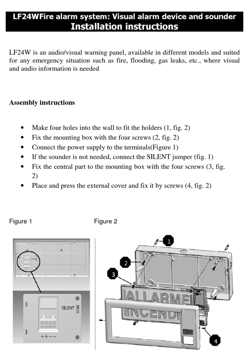
ELOTEC Confire User manual

(ORWHF&RQILUH Wireless Fire Alarm
Base Station - Call Point - Smoke Detector - Heat Detector
Installer and Operator
Handbook
Elotec AS
Søndre Industrivegen 3
N-7340 Oppdal
NORWAY
(ORWHF&RQILUH
Wireless Fire Alarm System
!!ELOTEC()*$#(+,+$"
!!!-./!&0123!405106
!!!-./!&0123!78295
:/("9;(-/<=!<->//>//
(ORWHF&RQILUH Wireless Fire Alarm System
R1A

Reset
Evacuate
Silent Test
Full Test
View Log
View Status
Status
Fault
Mercury Wireless Fire Alarm System
!!"#$%&$'()*$#(+,+$"
!-./!&0123!405106
!!!-./!&0123!78295
!:/("9;(-/<=!<->//>//
Status Fault
Mercury Wireless Fire Alarm System
About
Page 2 of 88
!"!!#$%&'()*+,(-(./(+
Document Identifier
Document Title
Date
!"0!1$)*.%*+
For further information, contact:
Elotec AS
Søndre Industrivegen 3, N-7340 Oppdal, Norway
https://elotec.com
Elotec Confire Fire Detection and Alarm System
Installer and Operator Handbook
Installer and Operator Handbook for Elotec Confire Fire alarms(869 MHz, EN54
Compliant).
March 2022
CONF-UMA

Reset
Evacuate
Silent Test
Full Test
View Log
View Status
Status
Fault
Mercury Wireless Fire Alarm System
!!"#$%&$'()*$#(+,+$"
!-./!&0123!405106
!!!-./!&0123!78295
!:/("9;(-/<=!<->//>//
Status Fault
Mercury Wireless Fire Alarm System
About
Page 3 of 88
0!2)*3$4&%*5$)+
0"!!,(65/5$)+75/*$38+
Revision history for the document is given in the table below.
Revision
Date
Revision Details
Table 1 - Document Revision History
0"0! 9.:-(+$;+1$)*()*/+
1.1!Document Release....................................................................................................................................................................................................................2!
1.2!Contact..............................................................................................................................................................................................................................................2!
2!Introduction.................................................................................................................................................................................................................................................3!
2.1!Revision History..........................................................................................................................................................................................................................3!
2.2!Table of Contents......................................................................................................................................................................................................................3!
2.3!Terms and Abbreviations .....................................................................................................................................................................................................5!
2.4!Elotec Confire Fire Detection and Fire Alarm System ................................................................................................................................................ 6
2.4.1!About...........................................................................................................................................................................................................................................6!
2.4.2!Quick Start ...............................................................................................................................................................................................................................8!
2.4.3!Principle of Operation...................................................................................................................................................................................................18!
3 Elotec Confire Base Station ........................................................................................................................................................................................................................... 25
3.1!Base Station Features ...........................................................................................................................................................................................................25!
3.2!Base Station Installation.......................................................................................................................................................................................................28!
3.2.1!Mounting.................................................................................................................................................................................................................................28!
3.2.2!Radio Range .........................................................................................................................................................................................................................29!
3.2.3!Setting to work...................................................................................................................................................................................................................29!
3.2.4!Testing......................................................................................................................................................................................................................................29!
3.2.5!Resetting following alarm activation.....................................................................................................................................................................29!
3.3!Indicators.......................................................................................................................................................................................................................................30!
3.4!OLED 4-line display...............................................................................................................................................................................................................31!
3.5!Audible and Visual Alerts...................................................................................................................................................................................................32!
3.6!Replacing the Battery............................................................................................................................................................................................................33!
Elotec Confire Fire Detection and Alarm System
Installer and Operator Handbook

Reset
Evacuate
Silent Test
Full Test
View Log
View Status
Status
Fault
Mercury Wireless Fire Alarm System
!!"#$%&$'()*$#(+,+$"
!-./!&0123!405106
!!!-./!&0123!78295
!:/("9;(-/<=!<->//>//
Status Fault
Mercury Wireless Fire Alarm System
About
Page 4 of 88
4 Elotec Confire Call Point.................................................................................................................................................................................................................................. 35
4.1!Features .........................................................................................................................................................................................................................................35!
4.2!Installation.....................................................................................................................................................................................................................................37!
4.2.1!Mounting................................................................................................................................................................................................................................37!
4.2.2!Radio Range.........................................................................................................................................................................................................................38!
4.2.3!Setting to work ..................................................................................................................................................................................................................38!
4.2.4!Testing......................................................................................................................................................................................................................................38!
4.2.5!Resetting following alarm activation ....................................................................................................................................................................39!
4.3!Indicators.......................................................................................................................................................................................................................................40!
4.4!Audible and Visual Alerts ..................................................................................................................................................................................................41!
4.4.1!Setting the Siren Loudness.........................................................................................................................................................................................42!
4.5!Replacing the Battery............................................................................................................................................................................................................44!
5 Elotec Confire Heat and Smoke Detectors ......................................................................................................................................................................................46
5.1!Features .........................................................................................................................................................................................................................................46!
5.2!Installation.....................................................................................................................................................................................................................................48!
5.2.1!Mounting................................................................................................................................................................................................................................48!
5.2.2!Radio Range.........................................................................................................................................................................................................................49!
5.2.3!Setting to work ..................................................................................................................................................................................................................49!
5.2.4!Testing......................................................................................................................................................................................................................................49!
5.2.5!Resetting following alarm activation ....................................................................................................................................................................50!
5.3!Indicators.......................................................................................................................................................................................................................................50!
5.4!Replacing the Battery............................................................................................................................................................................................................52!
6 Elotec Confire Tool ...........................................................................................................................................................................................................................................55
6.1!Software Configuration (Base Station Only)........................................................................................................................................................55!
6.1.1!Connecting............................................................................................................................................................................................................................55!
6.1.2!Setting Active Mode.......................................................................................................................................................................................................56!
6.1.3!Setting Transit Mode......................................................................................................................................................................................................57!
6.1.4!Basic Settings........................................................................................................................................................................................................................58!
6.1.5!Adding and Removing Units (Network)..........................................................................................................................................................60!
6.1.6!Event Logs.............................................................................................................................................................................................................................64!
6.1.7!Maintenance.........................................................................................................................................................................................................................65!
6.1.8!Unit Status.............................................................................................................................................................................................................................66!
6.2!Software Configuration (Call Point and Detector Only) ............................................................................................................................67!
6.2.1!Connecting............................................................................................................................................................................................................................67!
6.2.2!Setting Active Mode.......................................................................................................................................................................................................68!
6.2.3!Setting Transit Mode......................................................................................................................................................................................................69!
6.2.4!Basic Settings........................................................................................................................................................................................................................70!
Elotec Confire Fire Detection and Alarm System
Installer and Operator Handbook

Reset
Evacuate
Silent Test
Full Test
View Log
View Status
Status
Fault
Mercury Wireless Fire Alarm System
!!"#$%&$'()*$#(+,+$"
!-./!&0123!405106
!!!-./!&0123!78295
!:/("9;(-/<=!<->//>//
Status Fault
Mercury Wireless Fire Alarm System
About
Page 5 of 88
6.3!Determining Radio Network Performance...........................................................................................................................................................74!
7!Specifications...........................................................................................................................................................................................................................................76!
7.1!Elotec Confire Base Station ........................................................................................................................................................................................................... 76
7.1.1!Specification..........................................................................................................................................................................................................................76!
7.2!Elotec Confire Call Point ..................................................................................................................................................................................................................... 79
7.2.1!Specification..........................................................................................................................................................................................................................79!
7.3!Elotec Confire Smoke Detector ................................................................................................................................................................................................ 82
7.3.1!Specification..........................................................................................................................................................................................................................82!
7.4!Elotec Confire Heat Detectors ........................................... ..................................................................................................................................................... 85
7.4.1!Specification..........................................................................................................................................................................................................................85!
8!APPENDIX...............................................................................................................................................................................................................................................88!
8.1!Appendix A Base Stations Display States...............................................................................................................................................................88!
8.1.1!Normal Operation...........................................................................................................................................................................................................88!
0"<!9(3'/+.)4+=::3(65.*5$)/+
NOTE
CAUTION
WARNING
Anote isintended to draw the users attention to animportant part ofthe handbook.
Acaution denotes an instruction or advice to the user. Failure to comply with acaution may result in
malfunction or unexpected behaviour ofthe equipment.
Awarning denotes an instruction or advice tothe user. Failure tocomply with a warning may result
in harm or injury to personnel or property.
The Crossed out EN 54 symbol denotes an optional configuration or feature ofthe system whose
use is not covered by, or violates, a section ofthe EN 54standard. The use of such features isnot
covered bythe product’s EN 54certification. The user is responsible for enabling ordisabling such
features and does soat their own discretion.
Elotec Confire Fire Detection and Alarm System
Installer and Operator Handbook

Reset
Evacuate
Silent Test
Full Test
View Log
View Status
Status
Fault
Mercury Wireless Fire Alarm System
!!"#$%&$'()*$#(+,+$"
!-./!&0123!405106
!!!-./!&0123!78295
!:/("9;(-/<=!<->//>//
Status Fault
Mercury Wireless Fire Alarm System
About
Page 6 of 88
FIRE FIRST AID
(ORWHF&RQILUH Wireless Fire Alarm System
FIRST AID
FIRE
(ORWHF&RQILUH Wireless Fire Alarm System
FIRE FIRST AID
(ORWHF&RQ)LUH Wireless Fire Alarm System
(ORWHF&RQFiUH
Wireless Fire Alarm System
1
2
3
4
5
Elotec Confire Fire Detection and Alarm System
Installer and Operator Handbook
0">! Elotec Confire+@53(+#(*(%*5$)+.)4+@53(+=-.3'+A8/*('+
0">"!! =:$&*+
The Elotec Confire Fire Alarm series provides an EN 54 compliant modular Fire Detection and Fire Alarm (FDAS)
solution aimed, primarily, at the construction industry. The system is made up of devices for smoke / heat detection,
manual fire and first aid Call Points and a Base Station for status and fault indication.
Each element of the Elotec Confire Fire Alarm Series communicates to the other devices using radio frequency (RF) links
which permit rapid deployment and reconfiguration of the site as needed. Additionally, the smoke / heat detectors and
manual fire and first aid Call Points are battery operated – avoiding the need for fixed infrastructure and cabling.

Reset
Evacuate
Silent Test
Full Test
View Log
View Status
Status
Fault
Mercury Wireless Fire Alarm System
!!"#$%&$'()*$#(+,+$"
!-./!&0123!405106
!!!-./!&0123!78295
!:/("9;(-/<=!<->//>//
Status Fault
Mercury Wireless Fire Alarm System
About
Page 7 of 88
Key:
1 – Elotec Confire Base Station (ELOTEC CONFIRE)
2 – Elotec Confire Call Point (CONF-CP)
3 – Elotec Confire Detector:
with A1R type heat detector head (CONF-HEAT)
with Optical smoke detector head (CONF-OPT)
4 – Elotec Confire Heat / Smoke Detector acting as mesh extended network node
5 – Elotec Confire Call Point connected to the network via mesh extended network node
Highly Configurable, Readily Adaptable –
The Elotec Confire radio network supports up to 240 units consisting of any
combination of Call Points, heat detectors and smoke detectors. Units can be added and removed from the network as the
site dictates.
Extended “Mesh” Network –
Elotec Confire Call Points, Heat Detectors and Smoke Detectors automatically create a
mesh network. Units that are unable to communicate with the Base Station directly can pass their messages through
other Elotec Confire units that are able to communicate with the Base Station. The Elotec Confire mesh network allows
the range of the Fire Detection and Alarm System to be extended and to cope with problematic radio signal propagation
without the need to install a specific “repeater” type unit.
First Aid Call –
Elotec Confire Call Points include both Fire and First Aid Call Points. A different audible alert is used to
distinguish between Fire and First Aid.
Zones
– Elotec Confire Call Points, Heat Detectors and Smoke Detectors can be placed into “Zones”. The audible evacuate
alarm can be configured to evacuate the whole site, or just the zone in which the alarm was triggered. The Base Station
reports both the unit’s identity (unit ID) and its zone.
Elotec Confire Fire Detection and Alarm System
Installer and Operator Handbook

Reset
Evacuate
Silent Test
Full Test
View Log
View Status
Status
Fault
Mercury Wireless Fire Alarm System
!!"#$%&$'()*$#(+,+$"
!-./!&0123!405106
!!!-./!&0123!78295
!:/("9;(-/<=!<->//>//
Status Fault
Mercury Wireless Fire Alarm System
Quick
Start
Page 8 of 88
0">"0! B&5%C+A*.3*+
This section is intended to provide the installer with enough information to get the Elotec Confire Fire Detection and
Alarm System up and running. Further detail is provided throughout the remainder of the document.
!"#"!"$! %&'()*+,-).'-/')01&2-
The Elotec Confire network must be configured for use (this may have been carried out at the factory).
You will need:
1. USB-A to USB Mini-B Cable
2. PC running Elotec Confire Tool
NOTE:
Some minor variations may exist between Windows, Linux and Tablet versions of the software. The Linux
version is shown in these instructions. Features may be added, removed or modified at any time.
"#$#"#%#%! &'()*+,-*(+!./0!1(*.!
Each Call Point and Detector must be assigned to a network and be given a unique ID number within the network.
Before shipping, each unit is placed into an ultra-low power “transit” mode, so it is also necessary to activate the unit
before it can be used.
Instructions:
1. Connect the PC to the Elotec Confire Call Point or Detector using the USB Mini-B cable.
2. Run the Elotec Confire Tool.
3. Enter the “Network ID” (given by the Base Station), the “Device ID” (a unique number for the network) and a
zone (if required – see “Zones”, page 20).
4. Click “Save Settings”.
5. At the confirm dialog, click “Yes”.
4
3
5
Elotec Confire Fire Detection and Alarm System
Installer and Operator Handbook

Reset
Evacuate
Silent Test
Full Test
View Log
View Status
Status
Fault
Mercury Wireless Fire Alarm System
!!"#$%&$'()*$#(+,+$"
!-./!&0123!405106
!!!-./!&0123!78295
!:/("9;(-/<=!<->//>//
Status Fault
Mercury Wireless Fire Alarm System
Quick
Start
Page 9 of 88
6. Click “Set Active Mode”.
7. At the confirm dialog box, click “Yes”;
The unit will restart;
The “Status” and “Fault” LED indicators will flash until the unit has joined the network.
For further configuration options, refer to “Software Configuration (Call Point and Detector Only)”, page 67.
CAUTION: Take care when setting the unit ID and Network.
Setting the unit Network ID or device ID incorrectly may
prevent the correct operation of the system or, possibly, cause interference with other systems.
6
7
Elotec Confire Fire Detection and Alarm System
Installer and Operator Handbook

Reset
Evacuate
Silent Test
Full Test
View Log
View Status
Status
Fault
Mercury Wireless Fire Alarm System
!!"#$%&$'()*$#(+,+$"
!-./!&0123!405106
!!!-./!&0123!78295
!:/("9;(-/<=!<->//>//
Status Fault
Mercury Wireless Fire Alarm System
Quick
Start
Page 10 of 88
"#$#"#%#"! &'()*+,-*(+!./0!2340!5.3.*'(!
Each of the units must beadded tothe Base Station.
NOTE:
If the Base Station is already active, steps 2 through 4 can beomitted.
NOTE:
To reduce the time taken to join the network, remote units tobeadded to the network should be placed
into “transit” mode before they are added tothe Base Station and returned to “active” mode once the configuration is
complete.
Instructions:
1. Connect the PC to the Elotec Confire Base Station using the USB Mini-B cable.
2. Run the Elotec Confire Tool.
3. In the “Settings” tab, click “Set Active Mode”.
4. At the confirm dialog box, click “Yes”.
The unit will restart
5. (Optional) If the local date/time in the Base Station is incorrect, click “Set Clock from PC” in the “Settings” tab.
4
3
5
Elotec Confire Fire Detection and Alarm System
Installer and Operator Handbook

Reset
Evacuate
Silent Test
Full Test
View Log
View Status
Status
Fault
Mercury Wireless Fire Alarm System
!!"#$%&$'()*$#(+,+$"
!-./!&0123!405106
!!!-./!&0123!78295
!:/("9;(-/<=!<->//>//
Status Fault
Mercury Wireless Fire Alarm System
Quick
Start
Page 11 of 88
6. In the “Network” tab, click “Add Unit”.
7. Enter the unit ID for the unit to be added.
8. Press “OK”.
9. Each of the connected units will now join the network. The number of connected units is displayed on the Base
Station 4-line OLED display.
For further Base Station configuration options, refer to “Software Configuration (Base Station Only)” page 55.
6
8
7
!!!!"#$%!&'()!*+,)
!!!-./!01'(2!314'1)
!!!-./!01'(2!5#(+4
6/78+%7-/9:!9-;//;//
Elotec Confire Fire Detection and Alarm System
Installer and Operator Handbook

Reset
Evacuate
Silent Test
Full Test
View Log
View Status
Status
Fault
Mercury Wireless Fire Alarm System
!!"#$%&$'()*$#(+,+$"
!-./!&0123!405106
!!!-./!&0123!78295
!:/("9;(-/<=!<->//>//
Status Fault
Mercury Wireless Fire Alarm System
Quick
Start
Page 12 of 88
!"#"!"!! 3(*4*+,-).'-56(&7-
The Elotec Confire Fire Alarm is a Fire Detection and Alarm System. Its primary function is to protect personnel and
property by detection of the presence of fire and by sounding the alarm.
Figure 1 - Raising the Alarm
Confire allows the alarm to be raised by:
1 – Automatic detection of fire using heat or smoke detectors
2 – Manual detection of fire using Call Points
3 – Manual evacuation at the Base Station (e.g. in the site office)
Upon detection of a fire, Confire will sound an alarm at the triggered Call Point (if applicable) and an audible alert at the
Base Station (e.g. in the site office) before automatically sounding the alarm at other Call Points in the system.
The system may be configured into Zones so that the alert can be sounded in specific areas (see Zones, page 20). The
system may also be configured into “Double Knock” mode so that two Call Point triggers are required before the alarm
is sounded.
NOTE:
The double knock feature does not apply to smoke / heat detectors. The alarm will sound when a single detector
is activated irrespective of the configuration of the Base Station or Detector.
Reset
Evacuate
Silent Test
Full Test
View Log
View Status
Status
Fault
Mercury Wireless Fire Alarm System
!!"#$%&$'()*$#(+,+$"
!!!-./!&0123!405106
!!!-./!&0123!78295
:/("9;(-/<=!<->//>//
Status
Fault
Mercury Wireless Fire Alarm System
Status
Fault
Mercury Wireless Fire Alarm System
Status
Fault
Mercury Wireless Fire Alarm System
3
2
2
1
Status
Fault
Elotec Confi
tem
Reset
Evacuate
Test Comms
Mercury Wireless Fire Alarm System
Elotec Confire Fire Detection and Alarm System
Installer and Operator Handbook

Reset
Evacuate
Silent Test
Full Test
View Log
View Status
Status
Fault
Mercury Wireless Fire Alarm System
!!"#$%&$'()*$#(+,+$"
!-./!&0123!405106
!!!-./!&0123!78295
!:/("9;(-/<=!<->//>//
Status Fault
Mercury Wireless Fire Alarm System
Quick
Start
Page 13 of 88
Figure 2 - Sounding the Alarm
1 – Sounder at the triggered Call Point 2 – Buzzer at the Base Station
3 – Alarm sounded at other Call Points
!"#"!"8!9*6'+:*+,-).'-56(&7-
Following an alarm condition caused by a Call Point or Detector activation or by pressing the “Evacuate” button on the
Base Station, the cause of the alarm must be inspected and the system reset.
Procedure:
1. Press “Reset” for two (2) seconds at the Elotec Confire Base Station – the alarm will be silenced.
2. The Base Station will start a count down. Activated devices should be reset before the count down reaches zero
otherwise they will not be used by the system until the system is reset again.
Reset
Evacuate
Silent Test
Full Test
View Log
View Status
Status
Fault
Mercury Wireless Fire Alarm System
!!"#$%&$'()*$#(+,+$"
!!!-./!&0123!405106
!!!-./!&0123!78295
!:/("9;(-/<=!<->//>//
Status
Fault
Mercury Wireless Fire Alarm System
Status
Fault
Mercury Wireless Fire Alarm System
Status
Fault
Mercury Wireless Fire Alarm System
2
1
3
!!!!!!"#$#%%&'(
!!!!)*+!,-./01012
Reset
Evacuate
Test Comms
Full Test
View Log
View Status
Elotec ConFire Wir
Elotec Confire Fire Detection and Alarm System
Installer and Operator Handbook

Reset
Evacuate
Silent Test
Full Test
View Log
View Status
Status
Fault
Mercury Wireless Fire Alarm System
!!"#$%&$'()*$#(+,+$"
!-./!&0123!405106
!!!-./!&0123!78295
!:/("9;(-/<=!<->//>//
Status Fault
Mercury Wireless Fire Alarm System
Quick
Start
Page 14 of 88
3. Manually inspect and reset any activated Call Points (see “Resetting following alarm activation”, page 39).
4. Manually inspect any activated Heat / Smoke Detectors (see ”Resetting following alarm activation”, page 49).
If the inspection and reset procedure takes more than 30 seconds, the Base Station reset timer will expire. After the Call
Point or Detector is reset, the “Reset” key can be pressed again.
Elotec Confire Fire Detection and Alarm System
Installer and Operator Handbook

Reset
Evacuate
Silent Test
Full Test
View Log
View Status
Status
Fault
Mercury Wireless Fire Alarm System
!!"#$%&$'()*$#(+,+$"
!-./!&0123!405106
!!!-./!&0123!78295
!:/("9;(-/<=!<->//>//
Status Fault
Mercury Wireless Fire Alarm System
Quick
Start
Page 15 of 88
!"#"!"#! ;'4)*+,-).'-56(&7-
The Elotec Confire Fire Detection and Alarm System provides two means of testing the system.
Test Comms
Test Comms will cause the “Status” indicator on all attached devices to be illuminated. Test
Comms indicates that the devices are powered and connected to the system and is not a substitute for test alarm.
Test Alarm
Test Alarm will cause the sounder and beacon in all Call Points to be enabled (intermittent
pattern) to allow the sounders and beacons to be inspected.
"#$#"#$#%! Test Comms
Procedure:
1. Press “Test Comms” for two (2) seconds at the Elotec Confire Base Station.
The green status LED in all connected Call Points, Smoke Detectors and Heat Detectors will be illuminated
(continuous). The buzzer at the Base Station will sound.
2. Inspect each Elotec Confire Call Point, Smoke Detector and Heat Detector in turn and ensure the green status LED is
illuminated (continuous).
The comms test will expire after 1800 seconds by default and must be re-enabled if the inspection is incomplete.
The timeout can be extended – see “Basic Settings”, page 58.
3. Press “Reset” for 2 seconds at the Elotec Confire Base Station. The
green status LED in all connected devices will be extinguished.
4. The test is complete.
NOTE:
Pressing “Reset” for 2 seconds at any time during the test will cancel the test.
!!!!"#$%&'(!(&#("
)*++,!-./012123
!456.0,.!78.79!%&:,;
Reset
Evacuate
Test Comms
Full Test
View Log
View Status
FIRE FIRST AID
Elotec Confire Wireless Fire Alarm System
Reset
Evacuate
Test Comms
Test Alarm
View Log
View Status
Elotec ConFire Wireless Fire Alarm System
Elotec ConFire Wireless Fire Alarm System
FIRE FIRST AID
Elotec Confire Wireless Fire Alarm System
Elotec Confire Wireless Fire Alarm System Elotec Confire Wireless Fire Alarm System
Test Comms
Elotec Confire Fire Detection and Alarm System
Installer and Operator Handbook

Reset
Evacuate
Silent Test
Full Test
View Log
View Status
Status
Fault
Mercury Wireless Fire Alarm System
!!"#$%&$'()*$#(+,+$"
!-./!&0123!405106
!!!-./!&0123!78295
!:/("9;(-/<=!<->//>//
Status Fault
Mercury Wireless Fire Alarm System
Quick
Start
Page 16 of 88
"#$#"#$#"! Test Alarm!
Procedure:
1. Press “Test Alarm” for two (2) seconds at the Elotec Confire Base Station.
The audible and visual test in all connected Call Points will begin (evacuate tone, intermittent). The buzzer at the Base
Station will sound.
2. Inspect each Elotec Confire Call Point in turn and ensure the sounder and beacon are operating correctly.
The alarm test will expire after 300 seconds by default and must be re-enabled ifthe inspection isincomplete.
The timeout can be extended – see “Basic Settings”, page 58.
3. Press “Reset” for two (2) seconds at the Elotec Confire Base
Station. The audible and visual test will cease.
4. The test is complete.
NOTE:
Pressing “Reset” for 2 seconds at any time during the test will silence the alarm.
"#$%%!&'(&"
!!!)**+!,-./01012
!!!!3415-,!6-+67
Test Alarm
View Log
View Status
Mercury Wireless Fire Alarm System
FIRE FIRST AID
Elotec Confire Wireless Fire Alarm System
FIRE FIRST AID
Elotec ConFire Wireless Fire Alarm System
Test Alarm
Elotec Confire Fire Detection and Alarm System
Installer and Operator Handbook
Reset
Evacuate
Test Comms
Test Alarm
View Log
View Status
Elotec ConFire Wireless Fire Alarm System
Elotec ConFire Wireless Fire Alarm System Elotec ConFire Wireless Fire Alarm SystemElotec ConFire Wireless Fire Alarm System

Reset
Evacuate
Silent Test
Full Test
View Log
View Status
Status
Fault
Mercury Wireless Fire Alarm System
!!"#$%&$'()*$#(+,+$"
!-./!&0123!405106
!!!-./!&0123!78295
!:/("9;(-/<=!<->//>//
Status Fault
Mercury Wireless Fire Alarm System
Quick
Start
Page 17 of 88
1. Press “View Log” at the Elotec Confire Base Station.
The display will show the events stored in the system.
2. The log report is complete.
NOTE:
Only the most recent 20 events are stored. The oldest event will be cleared from memory for each new event
stored.
!"#"!"@!9A4)'7-9)()B4-
The status of the devices connected to the system can be viewed at the Base Station by pressing the “View Status”
button.
1. Press “View Status” at the Elotec Confire Base Station.
The display will show “All Units Normal” or will cycle through any faults where present in the system;
2. The status report is complete.
NOTE:
The system will periodically display the status page as part of its normal operation, the status button is provided as
a convenience.
x2
!"#$%&"$%'(!)'*!!+,-.
-+/"01/-.+2!.345.
6%)7($!$76$
!!!89:;;<=!0:>?@AB
!"#$%&"$%'(!)'*!!-,-.
-+/"01/-.+2!.3455
C767$
!!!89:;;<=!0:>?@AB
!"#$%&"$%'(!)'*!!D,-.
--/"01/-.+2!+.4--
!!!E=F;!-!/!G<=@!.
H%C7
!"#$%&"$%'(!)'*!!I,-.
-+/"01/-.+2!+.4-D
C767$
!!!89:;;<=!0:>?@AB
Test Alarm
View Log
View Status
Mercury Wireless Fire Alarm System
No faults
Faults Present
"#$#%"!&'()&#
!!!%*+,!-..!/!01*2!-
3''4"!&'"'#
!!5$66()73#!$5#78$#'4
"#$#%"!&'()&#
!!!$99!%*+,:!31;<=9
"#$#%"!&'()&#
!!!%*+,!-.!/!01*2!.
3''4"!&'"'#
!!4'#'5#)&!$5#78$#'4
"#$#%"!&'()&#
!!!%*+,!>>!/!01*2!.
"7?3$6!!6)"#
"#$#%"!&'()&#
!!!%*+,!-.-!/!01*2!-
6)@!A$##'&B
Test Alarm
View Log
View Status
Mercury Wireless Fire Alarm System
lotec
!"#"!"<! =>'+)-?1,,*+,-
The system will store the last twenty (20) events in its internal memory. These can be viewed bypressing the “View Log”
button. Events include alarm activations and fault conditions.
NOTE:
In order to use the logging feature, the time and date must be set correctly using the configuration too – see Basic
Settings, page 58.
CAUTI ON!
Failure to set the time and date may result inunexpected event logging behaviour!
Elotec Confire Fire Detection and Alarm System
Installer and Operator Handbook

Reset
Evacuate
Silent Test
Full Test
View Log
View Status
Status
Fault
Mercury Wireless Fire Alarm System
!!"#$%&$'()*$#(+,+$"
!-./!&0123!405106
!!!-./!&0123!78295
!:/("9;(-/<=!<->//>//
Status Fault
Mercury Wireless Fire Alarm System
Principle
of Operation
Page 18 of 88
Figure 3 - establishing device range
In order improve signal transmission, the Confire range will automatically:
Establish a “mesh” network
– Confire devices automatically creates a mesh network between units that allow
messages that cannot reach the Base Station directly to be passed through other units where possible.
Use alternative frequencies
– Confire devices automatically “hop” between different frequencies to reduce the
impact of momentary interference from 3rd party devices operating in the same frequency range.
In the event that reliable communication between units and the Base Station cannot be achieved, the installer can:
Move Devices
– Confire units can be re-deployed to remedy transmission problems with specific units. As units
are moved, the mesh network will automatically adapt to the new conditions.
Add Devices
– Adding more Confire units can improve transmission to/from existing units. Adding another unit
(Call Point or Detector) into the mesh network creates additional possible routes through which, messages can
be passed.
FIRE FIRST AID
Elotec Confire Wireless Fire Alarm System
Reset
Evacuate
Test Comms
Test Alarm
View Log
View Status
Elotec Confire Wireless Fire Alarm System
Status Fault
Elotec ConFire Wireless Fire Alarm System
Status Fault
Elotec ConFire Wireless Fire Alarm System
Status Fault
Elotec ConFire Wireless Fire Alarm System
Device out of
normal radio
range
Elotec Confire Fire Detection and Alarm System
Installer and Operator Handbook
0">"<! D35)%5E-(+$;+FE(3.*5$)+
!"#"8"$! C6(:'7'+)-1D-Confire-F+*)4-
Elotec state a nominal radio range of one (1) kilometre in free space – however this range is highly dependent upon site
conditions such as the weather and objects placed between the transmitter and the receiver such as buildings, temporary
structures, terrain and trees. Radio signals may also be affected by reflections caused by metallic structures or interference
from other systems operating in the same frequency range such as radio links.
Elotec Confire units communicate in both directions and, therefore, act as both transmitter and receiver. The radio path
loss may be asymmetric – i.e. the transmit and receive path may be unequally affected by the environment.
It is, therefore, difficult to estimate the performance of devices in the network accurately before they are installed in the
environment.

Reset
Evacuate
Silent Test
Full Test
View Log
View Status
Status
Fault
Mercury Wireless Fire Alarm System
!!"#$%&$'()*$#(+,+$"
!-./!&0123!405106
!!!-./!&0123!78295
!:/("9;(-/<=!<->//>//
Status Fault
Mercury Wireless Fire Alarm System
Principle
of Operation
Page 19 of 88
Elotec Confire Fire Detection and Alarm System
Installer and Operator Handbook
NOTE:
After moving a unit, ALWAYS perform a Comms Test (see “Test Comms”, page 15) to confirm that the unit
is connected to the network and confirm that the Base Station does not report any faults. It should be noted that,
because of the mesh network, moving a unit to improve the communication to/from one unit may have the opposite
effect for another unit in the network.
Further guidance on how to determine the performance of the radio network is given in “Placement of Confire Units”
page 18. In case of difficulties achieving acceptable network coverage and/or range, please contact Elotec.

Reset
Evacuate
Silent Test
Full Test
View Log
View Status
Status
Fault
Mercury Wireless Fire Alarm System
!!"#$%&$'()*$#(+,+$"
!-./!&0123!405106
!!!-./!&0123!78295
!:/("9;(-/<=!<->//>//
Status Fault
Mercury Wireless Fire Alarm System
Principle
of Operation
Page 20 of 88
!"#"8"!! G1+'4-
The Elotec Confire Fire Detection and Alarm System (FDAS) provides eight (8) zones (0 to 7). Detectors and Call
Points may be assigned to a zone during the configuration step.
Figure 4 - Zone Configuration
Zone 0
– Special Zone. If an alarm is generated by a Detector or Call Point in zone 0, it will trigger an evacuation of all
zones triggering an audible and visual alarm at all Call Points in the network.
Zone 1-7
– Normal zones. An alarm generated in this zone will trigger an audible and visual alarm in all Call Points within
the zone. An audible and visual alarm will also be triggered in zone 0.
Z
O
N
E
1
Z
O
N
E
2
Z
O
N
E
3
Z
O
N
E
4
Z
O
N
E
5
Z
O
N
E
6
Z
O
N
E
7
Z
O
N
E
0
Reset
Evacuate
Test Comms
Test Alarm
View Log
View Status
Status
Fault
Elotec Confire Wireless Fire Alarm System
!!ELOTEC()*$#(+,+$"
!!!-./!&0123!405106
!!!-./!&0123!78295
:/("9;(-/<=!<->//>//
FIRE
HEAT/
SMOKE
FIRE
FIRE
HEAT/
SMOKE
FIRE
HEAT/
SMOKE
FIRE
FIRE
HEAT/
SMOKE
FIRE
HEAT/
SMOKE
FIRE
FIRE
HEAT/
SMOKE
FIRE
HEAT/
SMOKE
FIRE
FIRE
HEAT/
SMOKE
FIRE
HEAT/
SMOKE
FIRE
FIRE
HEAT/
SMOKE
FIRE
HEAT/
SMOKE
FIRE
FIRE
HEAT/
SMOKE
FIRE
HEAT/
SMOKE
FIRE
FIRE
HEAT/
SMOKE
FIRE
HEAT/
SMOKE
FIRE
FIRE
HEAT/
SMOKE
Elotec Confire Fire Detection and Alarm System
Installer and Operator Handbook
Table of contents
