997-532-000-1, Issue 1
March 2006
i
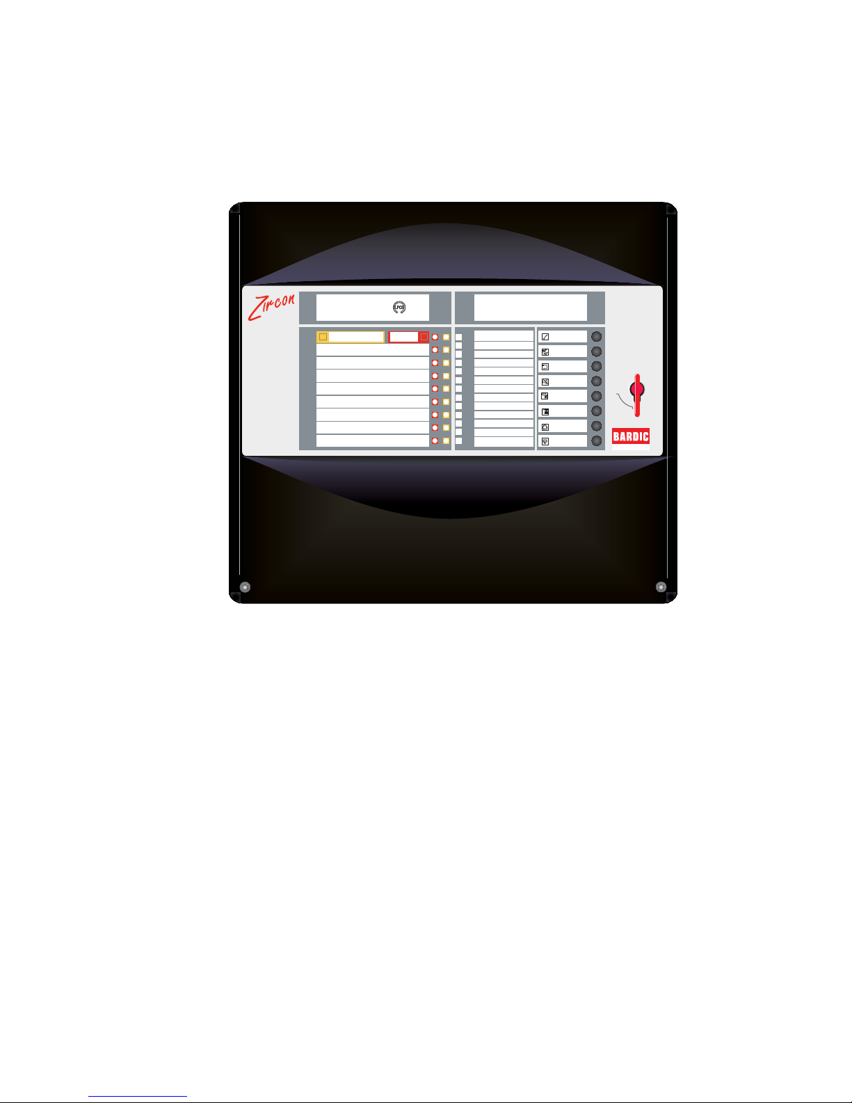
EN54 & ISO 7240 2-8 Zone Conventional Fire Panel - Installation & Configuration Manual
Contents
1 Introduction
1.1 Manual Purpose.............................................. 1
1.2 System Design & Planning.............................. 1
1.2.1 Personel..................................................... 1
1.3 General ........................................................... 1
1.4 CE Marking ..................................................... 2
1.5 EN54 & ISO 7240 Functions ........................... 3
1.6 Ancillary Functions .......................................... 4
1.7 Related Documents ........................................ 4
1.8 Warnings & Cautions ...................................... 4
2 Installation Guide
2.1 How to Use this Guide .................................... 5
2.2 Pre-installation Check List .............................. 5
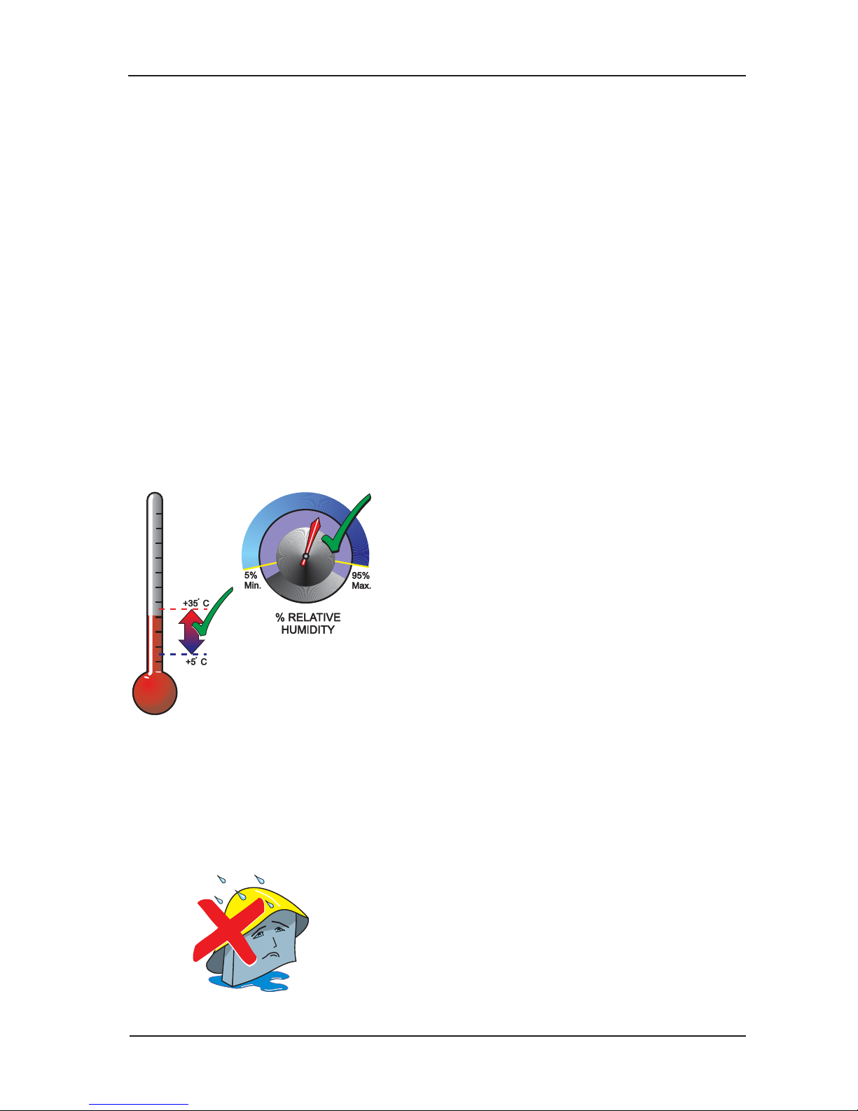
2.2.1 Some Panel DO’s and DON’Ts .................. 5
2.3 Transient Protection ........................................ 6
2.4 Product Inspection .......................................... 7
2.4.1 Checking Your Panel for Damage .............. 7
2.4.2 What to do if Your Panel is Damaged .............. 7
2.5 InstallationPreparation ................................... 8
2.5.1 Removing the Cover .................................. 8
2.5.2 Back Box Fixing ......................................... 8
2.6 Optional Equipment ........................................ 9
2.6.1 2-Way Relay PCB ...................................... 9
2.6.2 8-Way Relay PCB ...................................... 9
3 Cabling
3.1 Cabling Instructions ...................................... 10
3.1.1 Cable Terminations ...................................11
3.2 Quality of Cable and of Cable Installation...........11
3.3 EMC Considerations ..................................... 12
3.4 Cables for Sounder Circuits .......................... 12
4 Field Devices
4.1 End-of -Line Devices..................................... 13
5 Panel Electronics
5.1 Main PCB...................................................... 14
5.2 PSU PCB ...................................................... 15
5.3 Label Inserts ................................................. 15
6 Commissioning
6.1 Introduction ................................................... 16
6.2 Preliminary Checks ....................................... 16
6.3 External Wiring ........................................ 16
6.3.1 Zone Wiring - New Installation ................. 16
6.3.2 Zone Wiring - Retrofit Installation............. 16
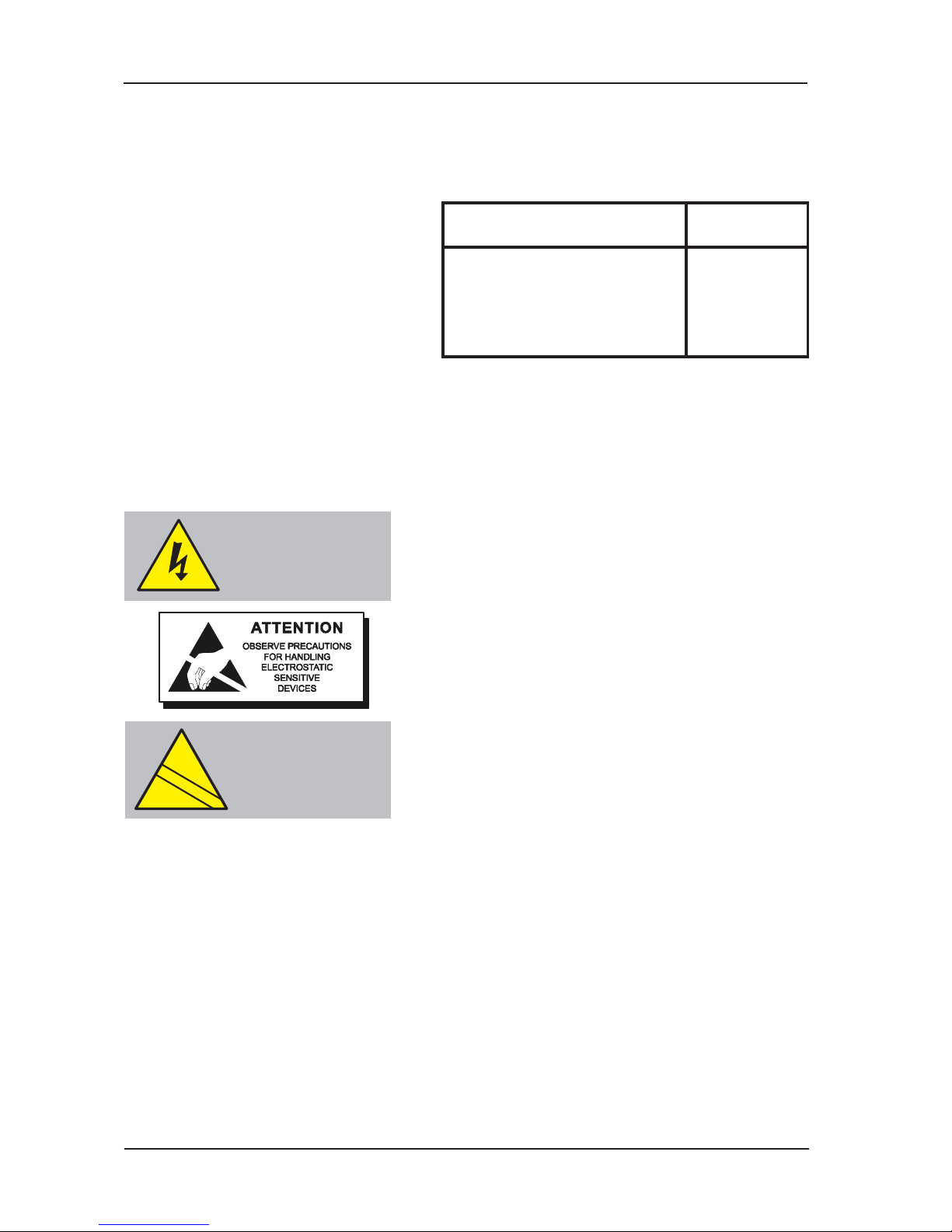
The following markings are used either on
thepanelhardwareorinthedocumentation.
They have the following meaning:
WARNING: Risk of electric shock.
Before working on mains
connections, ensure mains
power supply to the panel
is disconnected.
CAUTION: Refer to the accompanying
documentation. (When
used in the documentation,
this marking is normally
associated with additional
instructions).
!
EN54
ISO 7240