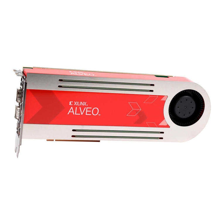
Xilinx Alveo U50 User manual

Revision History
The following table shows the revision history for this document.
Section Revision Summary
12/18/2019 Version 1.2
Card Features Added a note about HBM pseudo channels.
FPGA Configuration Updated the clock rate for FPGA_CCLK.
UltraScale+ FPGA Added a note about HBM pseudo channels.
Maintenance Connector Interface Added a tip about the Alveo Programming Cable.
SFP-DD Module Connectors Added a note about the supported interfaces.
Status LEDs Updated the tables and added a new table.
10/31/2019 Version 1.1
General updates. Updated to the Vitis unified software platform throughout.
Chapter 1: Introduction •Removed HBM2 bandwidth from first paragraph.
•Updated figure.
•Updated description of card interfaces.
Card Features •Removed bullets about HBM2 memory.
•Added note about power rails.
Board Support Files for the Alveo U50 Card Added link for Xilinx Board Store to introductory paragraph.
Card Power System •Updated paragraph with power rail information.
•Added tip about monitoring power system telemetry.
Appendix B: Regulatory and Compliance Information Added safety, EMC, and other compliance information.
09/10/2019 Version 1.0.1
General updates. Editorial updates only. No technical content updates.
08/02/2019 Version 1.0
Initial release N/A
Revision History
UG1371 (v1.2) December 18, 2019 www.xilinx.com
Alveo U50 Accelerator Card User Guide 2
Send Feedback

Table of Contents
Revision History...............................................................................................................2
Chapter 1: Introduction.............................................................................................. 5
Card Features...............................................................................................................................7
Block Diagram..............................................................................................................................7
Design Flows................................................................................................................................ 9
Chapter 2: Vivado Design Flow..............................................................................10
Board Support Files for the Alveo U50 Card.......................................................................... 10
Creating an RTL Project Based on the U50 Board File..........................................................11
Creating an MCS File and Programming the Alveo Card..................................................... 12
Chapter 3: Card Installation and Configuration......................................... 14
Standard ESD Measures........................................................................................................... 14
Installing Alveo Data Center Accelerator Cards in Server Chassis......................................15
FPGA Configuration...................................................................................................................15
Chapter 4: Card Component Description........................................................ 16
UltraScale+ FPGA....................................................................................................................... 16
Quad SPI Flash Memory........................................................................................................... 16
Maintenance Connector Interface.......................................................................................... 17
PCI Express Endpoint................................................................................................................17
SFP-DD Module Connectors.....................................................................................................18
I2C Bus........................................................................................................................................18
Status LEDs.................................................................................................................................18
Card Power System................................................................................................................... 19
Appendix A: Xilinx Design Constraints (XDC) File...................................... 21
Appendix B: Regulatory and Compliance Information........................... 22
Safety Compliance.....................................................................................................................22
EMC Compliance........................................................................................................................22
CE Directives.............................................................................................................................. 23
UG1371 (v1.2) December 18, 2019 www.xilinx.com
Alveo U50 Accelerator Card User Guide 3
Send Feedback

CE Standards..............................................................................................................................23
Compliance Markings............................................................................................................... 24
Other Compliance Statements................................................................................................ 24
Appendix C: Additional Resources and Legal Notices............................. 28
Xilinx Resources.........................................................................................................................28
Documentation Navigator and Design Hubs.........................................................................28
References..................................................................................................................................28
Please Read: Important Legal Notices................................................................................... 30
UG1371 (v1.2) December 18, 2019 www.xilinx.com
Alveo U50 Accelerator Card User Guide 4
Send Feedback

Chapter 1
Introduction
The Xilinx® Alveo™ U50 Data Center accelerator cards are peripheral component interconnect
express (PCIe®) Gen3 x16 compliant and Gen4 x8 compable cards featuring the Xilinx 16 nm
UltraScale+™ technology. The Alveo U50 card oers 8 GB of HBM2 to provide high-
performance, adaptable acceleraon for memory-bound, compute-intensive applicaons
including database, analycs, and machine learning inference.
The following table lists the specicaons for the engineering sample (ES3) and producon (PQ)
versions of the Alveo U50 accelerator cards.
Table 1: Alveo Card Specifications
Specification ES3 Version PQ Version
Product SKU A-U50DD-P00G-ES3-G A-U50-P00G-PQ-G
Network interface 2xSFP-DD 1XQSFP
Qualified for deployment No Yes
UG1371 (v1.2) December 18, 2019 www.xilinx.com
Alveo U50 Accelerator Card User Guide 5
Send Feedback

The Alveo™ U50 card is available in a passive cooling conguraon only and is designed for
installaon into a data center server where controlled air ow provides direct cooling to the card.
The following gure shows the Alveo U50 accelerator card with half-height bracket installed. The
card includes the following interfaces:
1. A PCI Express® card connector.
2. One QSFP interface.
Note: For ES3 cards, two SFP-DD interfaces are available.
3. Maintenance Connector.
Figure 1: Alveo U50 Data Center Accelerator Card
Maintenance Connector
QSFP28
Interface
PCIe Connector
X22929-101519
CAUTION! Alveo accelerator cards are designed to be installed into a data center server, where controlled air
ow provides direct cooling. If the cooling enclosure is removed from the card and the card is powered-up,
external fan cooling airow MUST be applied to prevent over-temperature shut-down and possible damage to
the card electronics. Removing the cooling enclosure voids the board warranty.
See Appendix C: Addional Resources and Legal Noces for references to documents, les, and
resources relevant to the Alveo U50 accelerator cards.
Chapter 1: Introduction
UG1371 (v1.2) December 18, 2019 www.xilinx.com
Alveo U50 Accelerator Card User Guide 6
Send Feedback

Card Features
The Alveo U50 accelerator card features are listed below. Detailed informaon for each feature is
provided in Chapter 4: Card Component Descripon.
• UltraScale+™ XCU50 FPGA
• Two 4 gigabyte (GB) HBM memory stacks (8 GB total)
○32 channels of 256 MB
Note: The xilinx_u50_xdma_201920_2 plaorm allows a maximum of 30 of the 32 available HBM
pseudo channels to be used. Using more will generate errors during hardware build. Xilinx
recommends using pseudo-channels 0:29 because pseudo channels 30 and 31 need to route across
fabric resources shared with the stac region possibly resulng in lower performance.
• One gigabit (Gb) quad SPI ash memory for conguraon
• Ethernet networking interfaces
○Two SFP-DD connectors support 4x10/25 GbE (ES3 card)
○One QSFP28 connector supporng 100 GbE, 40 GbE, or 4x10/25 GbE (PQ card)
• JTAG and UART access through the maintenance connector
• 16-lane integrated Endpoint block for PCI Express connecvity
○Gen3 x16 supporng to x1, x2, x4, x8, x16 lane conguraons
○Single or dual Gen4 x8
• I2C bus
• Status LEDs
• Power management with system management bus (SMBus) voltage, current, and temperature
monitoring
• 75W PCIe slot power only
Note: The Alveo U50 card has separate power rails for FPGA fabric and HBM memory. Developers must
ensure their designs do not draw too much power for each rail. More informaon can be found in the
Known Issues table of the Alveo U50 Data Center Accelerator Card Installaon Guide (UG1370).
Block Diagram
Block diagrams of the Alveo U50 card with two SFP-DD interfaces (ES3 card) and one QSFP
interface (PQ card) are shown in the following gures.
Chapter 1: Introduction
UG1371 (v1.2) December 18, 2019 www.xilinx.com
Alveo U50 Accelerator Card User Guide 7
Send Feedback

Figure 2: Card Block Diagram with SFP-DD Interface
Xilinx
XCU50
QSPI
Satellite
Controller
HBM
4 GB
U50
GTY x4
EP GTY x16
Single QSPI
Config Flash
HBM
4 GB
UART
PCIe
(Gen3 x16 or
two Gen4 x8)
SFP-DD 2x 25 Gb/s
SFP-DD 2x 25 Gb/s
SMBus
X22932-072919
Figure 3: Card Block Diagram with QSFP Interface
Xilinx
XCU50
QSPI
Satellite
Controller
HBM
4 GB
U50
GTY x4
EP GTY x16
Single QSPI
Config Flash
HBM
4 GB
UART
PCIe
(Gen3 x16 or
two Gen4 x8)
QSFP28 4 GTY
SMBus
100 GbE
40 GbE
4x 10 GbE
X22939-072919
Chapter 1: Introduction
UG1371 (v1.2) December 18, 2019 www.xilinx.com
Alveo U50 Accelerator Card User Guide 8
Send Feedback

Design Flows
The preferred opmal design ow for targeng the Alveo Data Center accelerator card uses the
Vis™ unied soware plaorm. However, tradional design ows, such as RTL or HLx are also
supported using the Vivado® Design Suite tools. The following gure shows a summary of the
design ows.
Figure 4: Alveo Data Center Accelerator Card Design Flows
High complexity
Slowest
High
Simplicity
Time to Market
Hardware Expertise Required
Complexity abstracted
Fastest
Low
RTL Flow HLx Flow (IP integrator)
Traditional Flows
Target Platform
Vitis
X22272-020419
Requirements for the dierent design ows are listed in the following table.
Table 2: Requirements to Get Started with Alveo Data Center Accelerator Card Design
Flows
RTL Flow HLx Flow Vitis
Flow documentation UG9491UG8952UG14163
Vivado tools support Board support XDC Board support XDC N/A
Programming the FPGA Vivado Hardware Manager Vivado Hardware Manager UG13704
Notes:
1. UltraFast Design Methodology Guide for the Vivado Design Suite (UG949).
2. Vivado Design Suite User Guide: System-Level Design Entry (UG895). See “Using the Vivado Design Suite Platform Board
Flow” in Chapter 2 and Appendix A.
3. Vitis Accelerated Flow in the Vitis Unified Software Platform Documentation (UG1416).
4. Alveo U50 Data Center Accelerator Card Installation Guide (UG1370).
Chapter 1: Introduction
UG1371 (v1.2) December 18, 2019 www.xilinx.com
Alveo U50 Accelerator Card User Guide 9
Send Feedback

Chapter 2
Vivado Design Flow
This secon provides a starng point for expert HDL developers using the RTL ows, or
developers who want to customize in HLx beyond the standard support in the Vivado® tools.
Board Support Files for the Alveo U50 Card
Prior to creang an RTL project based on the Alveo™ U50 card, update the board support
repository to include the Alveo U50 card by following the steps listed below. Board support les
can also be downloaded from the Xilinx Board Store.
1. Launch Vivado tools.
2. Download the latest board les by selecng Tools → Download Latest Boards….
3. Click Download in the Download Latest Boards dialog box. This will download all the latest
board support les including those for the Alveo U50 card. The download may take several
minutes to complete.
Chapter 2: Vivado Design Flow
UG1371 (v1.2) December 18, 2019 www.xilinx.com
Alveo U50 Accelerator Card User Guide 10
Send Feedback

Creating an RTL Project Based on the U50
Board File
For designers using RTL ow, use the following steps to create an RTL project using the U50
board le.
1. Launch Vivado tools.
2. Create a new project by clicking on File → Project → New. Click Next.
3. Add a project name and click Next.
4. Select RTL Project as the Project Type and click Next.
5. Within the Default Part window, select Boards and enter u50 in the search tab. Select the
U50 card and click Next as shown in the following gure.
This will create a new RTL project based on the Alveo U50 accelerator card.
Chapter 2: Vivado Design Flow
UG1371 (v1.2) December 18, 2019 www.xilinx.com
Alveo U50 Accelerator Card User Guide 11
Send Feedback

Creating an MCS File and Programming the
Alveo Card
For custom RTL ow, this secon outlines the procedures to do the following:
• Create an MCS le (PROM image)
• Flash program through the maintenance connector
Create an MCS File (PROM Image)
To ensure that the PROM image is successfully loaded onto the Alveo accelerator card at power
on, the starng address must be set to 0x01002000 and the interface set to spix4 when
creang the MCS le. Details on adding this to the MCS le can be found in the UltraScale
Architecture Conguraon User Guide (UG570).
The Alveo accelerator card's Quad SPI conguraon ash memory contains a protected region,
with the factory base image at the 0x00000000 address space. This base image points to the
customer programmable region at a 0x01002000 address space oset.
In addion, the following code must be placed in the project XDC le to correctly congure the
MCS le.
# Bitstream Configuration
# ------------------------------------------------------------------------
set_property CONFIG_VOLTAGE 1.8 [current_design]
set_property BITSTREAM.CONFIG.CONFIGFALLBACK Enable [current_design]
set_property BITSTREAM.GENERAL.COMPRESS TRUE [current_design]
set_property CONFIG_MODE SPIx4 [current_design]
set_property BITSTREAM.CONFIG.SPI_BUSWIDTH 4 [current_design]
set_property BITSTREAM.CONFIG.CONFIGRATE 85.0 [current_design]
set_property BITSTREAM.CONFIG.EXTMASTERCCLK_EN disable [current_design]
set_property BITSTREAM.CONFIG.SPI_FALL_EDGE YES [current_design]
set_property BITSTREAM.CONFIG.UNUSEDPIN Pullup [current_design]
set_property BITSTREAM.CONFIG.SPI_32BIT_ADDR Yes [current_design]
# ------------------------------------------------------------------------
Once the XDC le has been updated, generate the MCS le using the following command (note
the quotaons are required):
write_cfgmem -force -format mcs -interface spix4 -size 1024 -loadbit "up 0x01002000
<input_le.bit>" -le "<output_le.mcs>"
Where:
•<input_le.bit> is the lename of the input .bit le
•<output_le.mcs> is the MCS output lename
Chapter 2: Vivado Design Flow
UG1371 (v1.2) December 18, 2019 www.xilinx.com
Alveo U50 Accelerator Card User Guide 12
Send Feedback

Program the Alveo Card
Aer the MCS le is created, use the following steps to ash the Alveo Data Center accelerator
card using the Vivado hardware manager through the debug and maintenance board (DMB).
Details on connecng to the Alveo card through the maintenance connector are provided in the
Alveo Programming Cable User Guide (UG1377). Detailed steps for programming the FPGA are
outlined in the chapter Programming the FPGA Device in the Vivado Design Suite User Guide:
Programming and Debugging (UG908).
RECOMMENDED: Programming through JTAG maintenance port must be from a separate machine to avoid
PCIe downlink causing the server to reboot during programming. Alternavely, the PCIe link can be manually
disabled through soware and rescanned aer programming is complete.
1. Connect to the Alveo U50 Data Center accelerator card using the Vivado hardware manager
through the DMB.
2. Select Add Conguraon Device and select the mt25qu01g-spi-x1_x2_x4 part.
3. Right-click the target to select Program the Conguraon Memory Device.
a. Select the MCS le target.
b. Select Conguraon File Only.
c. Click OK.
4. Aer programming has completed, disconnect the card in the hardware manager, and
disconnect the USB cable from the Alveo accelerator card.
5. Perform a cold reboot on the host machine to complete the card update.
IMPORTANT! If you are switching between an Alveo Data Center accelerator card target plaorm and a
custom design, revert the card to the golden image before loading an alternate image into the PROM. See Alveo
U50 Data Center Accelerator Card Installaon Guide (UG1370) for more informaon.
Chapter 2: Vivado Design Flow
UG1371 (v1.2) December 18, 2019 www.xilinx.com
Alveo U50 Accelerator Card User Guide 13
Send Feedback

Chapter 3
Card Installation and Configuration
Standard ESD Measures
CAUTION! ESD can damage electronic components when they are improperly handled, and can result in total
or intermient failures. Always follow ESD-prevenon procedures when removing and replacing components.
To prevent ESD damage:
•Aach a wrist strap to an unpainted metal surface of your hardware to prevent electrostac
discharge from damaging your hardware.
• When you are using a wrist strap, follow all electrical safety procedures. A wrist strap is for
stac control. It does not increase or decrease your risk of receiving electric shock when you
are using or working on electrical equipment.
• If you do not have a wrist strap, before you remove the product from ESD packaging and
installing or replacing hardware, touch an unpainted metal surface of the system for a
minimum of ve seconds.
• Do not remove the device from the anstac bag unl you are ready to install the device in
the system.
• With the device sll in its anstac bag, touch it to the metal frame of the system.
• Grasp cards and boards by the edges. Avoid touching the components and gold connectors on
the adapter.
• If you need to lay the device down while it is out of the anstac bag, lay it on the anstac
bag. Before you pick it up again, touch the anstac bag and the metal frame of the system at
the same me.
• Handle the devices carefully to prevent permanent damage.
Chapter 3: Card Installation and Configuration
UG1371 (v1.2) December 18, 2019 www.xilinx.com
Alveo U50 Accelerator Card User Guide 14
Send Feedback

Installing Alveo Data Center Accelerator
Cards in Server Chassis
For hardware and soware installaon procedures, see the Alveo U50 Data Center Accelerator
Card Installaon Guide (UG1370).
Because each server or PC vendor's hardware is dierent, for physical board installaon
guidance, see the manufacturer’s PCI Express® board installaon instrucons.
FPGA Configuration
The Alveo U50 accelerator card supports two UltraScale+™ FPGA conguraon modes:
• Quad SPI ash memory
• JTAG (through maintenance port)
The FPGA bank 0 mode pins are hardwired to M[2:0] = 001 master SPI mode with pull-up/down
resistors.
At power up, the FPGA is congured by the QSPI NOR ash device (Micron
MT25QU01GBB8E12-0SIT) with the FPGA_CCLK operang at a clock rate of up to 85 MHz
using the master serial conguraon mode.
If the JTAG cable is plugged in, QSPI conguraon might not occur. JTAG mode is always
available independent of the mode pin sengs.
For complete details on conguring the FPGA, see the UltraScale Architecture Conguraon User
Guide (UG570).
Table 3: Configuration Modes
Configuration Mode M[2:0] Bus Width CCLK Direction
Master SPI 001 x1, x2, x4 FPGA output
JTAG Not applicable – JTAG overrides x1 Not applicable
Chapter 3: Card Installation and Configuration
UG1371 (v1.2) December 18, 2019 www.xilinx.com
Alveo U50 Accelerator Card User Guide 15
Send Feedback

Chapter 4
Card Component Description
This chapter provides a funconal descripon of the components of the Alveo™ U50 Data
Center accelerator card.
UltraScale+ FPGA
The Alveo U50 accelerator card is populated with the 16 nm UltraScale+™ XCU50 FPGA.
This UltraScale+ HBM device incorporates two 4 GB high-bandwidth memory (HBM) stacks
adjacent to the device die. Using SSI technology, the device communicates to the HBM stacks
through memory controllers that connect through the silicon interposer at the boom of the
device. Each XCU50 FPGA contains two 4 GB HBM stacks, resulng in up to 8 GB of HBM per
device. The device includes 32 HBM AXI interfaces used to communicate with the HBM. The
exible addressing feature that is provided by a built-in switch allows for any of the 32 HBM AXI
interfaces to access any memory address on either one or both of the HBM stacks. This exible
connecon between the device and the HBM stacks is helpful for oorplanning and ming
closure.
Note: The xilinx_u50_xdma_201920_2 plaorm allows a maximum of 30 of the 32 available HBM pseudo
channels to be used. Using more will generate errors during hardware build. Xilinx recommends using
pseudo-channels 0:29 because pseudo channels 30 and 31 need to route across fabric resources shared
with the stac region possibly resulng in lower performance.
Quad SPI Flash Memory
The Quad SPI device provides 1 Gb of nonvolale storage.
• Part number: MT25QU01GBBB8E12-0AAT (Micron)
• Supply voltage: 1.8V
• Datapath width: 4 bits
• Data rate: variable
Chapter 4: Card Component Description
UG1371 (v1.2) December 18, 2019 www.xilinx.com
Alveo U50 Accelerator Card User Guide 16
Send Feedback

For conguraon details, see the UltraScale Architecture Conguraon User Guide (UG570). The
detailed FPGA and Flash pin connecons for the feature described in this secon are
documented in the Alveo U50 accelerator card XDC le, referenced in Appendix A: Xilinx Design
Constraints (XDC) File.
Maintenance Connector Interface
The Alveo U50 accelerator card provides access to the FPGA through the JTAG interface using a
debug and maintenance board (DMB) connected to the 30-pin maintenance connector. The
connector pinout supports three UART debug interfaces: PMBus, FPGA JTAG, and satellite
controller JTAG. The following gure shows the maintenance connector interface. For more
informaon, see Alveo Programming Cable User Guide (UG1377).
Figure 5: Maintenance Connector
Maintenance
Connector
2x15
Satellite
Controller
MSP432
JTAG1
SC_UART_RXD/TXD
FPGA_TXD/RXD_MSP
XLT
XLT
Control from SC
JTAG0
UART0
X22955-072919
XCU50
FPGA
TIP: The Alveo Programming Cable is not provided with the U50 (QSFP) producon card. This cable can be
purchased at the following link: hps://www.xilinx.com/products/boards-and-kits/alveo/accessories.html.
PCI Express Endpoint
The Alveo U50 accelerator card implements a 16-lane PCI Express edge connector that performs
data transfers at the rate of 2.5 giga-transfers per second (GT/s) for Gen1, 5.0 GT/s for Gen2, 8.0
GT/s for Gen3 applicaons, and 16.0 GT/s for Gen4 applicaons.
Chapter 4: Card Component Description
UG1371 (v1.2) December 18, 2019 www.xilinx.com
Alveo U50 Accelerator Card User Guide 17
Send Feedback

The detailed FPGA connecons for this feature are documented in the Alveo U50 accelerator
card Xilinx Design Constraints (XDC) le, referenced in Appendix A: Xilinx Design Constraints
(XDC) File.
SFP-DD Module Connectors
The Alveo U50 accelerator cards host two small form-factor pluggable (SFP-DD) connectors that
accept an array of opcal modules. Each connector is housed within a single cage assembly and
are accessible through the I2C interface.
Access from the FPGA to SFP-DD modules and support for miscellaneous SFP-DD signals is
provided through the satellite controller. For more informaon about the SFP-DD module, see
SFP-DD Specicaon.
• MGTREFCLK0 is from SI5394 with programmable output frequencies
• Maximum SFP-DD power is 3.5W per port
• The target for SFP-DD channel length is 4 inches maximum
Note: The Alveo U50 card that includes one QSFP interface is producon qualied for deployment. The
Alveo U50DD ES3 card that supports two SFP-DD interfaces is not recommended for deployment.
Detailed FPGA connecons for this feature are documented in the Alveo U50 accelerator card
XDC le, referenced in Appendix A: Xilinx Design Constraints (XDC) File.
I2C Bus
The Alveo U50 accelerator cards implement an I2C bus network.
Status LEDs
The U50 has two set of LEDs:
1. Card status LEDs
2. Ethernet status LEDs
Card status LEDs are visible through a cutout in the PCIe end bracket and are dened in the
following table. Producon cards will not have board status LEDs.
Chapter 4: Card Component Description
UG1371 (v1.2) December 18, 2019 www.xilinx.com
Alveo U50 Accelerator Card User Guide 18
Send Feedback

Table 4: Card Status LEDs
Reference Designator Description
ES Production
DS1 When FPGA is configured, LED is blue, otherwise it remains Off
DS2 System healthy when green1Not populated
DS3 Warning or alarm when orange1Not populated
DS4 Power fault when red Not populated
Notes:
1. Functionality is not yet defined.
Ethernet status LEDs are located on the top-le, front panel above the SFP-DD modules. The
LED denions are given in the following tables.
Table 5: ES Ethernet Status LEDs
Reference Designator Description
SFPDD_0_ACT Dedicated to Activity and is only green1
SFPDD_0_STA Dedicated to Link and is yellow/green1
SFPDD_1_ACT Dedicated to Activity and is only green1
SFPDD_1_STA Dedicated to Link and is yellow/green1
Notes:
1. Functionality is not yet defined.
Table 6: PQ Ethernet Status LEDs
Reference Description
QSFP_0_ACT Dedicated to Activity and is only green1
QSFP_0_STA Dedicated to Link and is yellow/green1
Notes:
1. Functionality is not yet defined.
Card Power System
The Alveo U50 card has separate power rails for FPGA fabric and HBM memory. Developers
must ensure their designs do not draw too much power for each rail. More informaon can be
found in the Known Issues table of the Alveo U50 Data Center Accelerator Card Installaon Guide
(UG1370). To monitor, limited power system telemetry is available through the I2C IP. I2C IP is
instanated during the FPGA design process which begins aer the Alveo Data Center
accelerator card is selected from the Vivado Design Suite Boards tab. Refer to Design Flows for
more informaon.
Chapter 4: Card Component Description
UG1371 (v1.2) December 18, 2019 www.xilinx.com
Alveo U50 Accelerator Card User Guide 19
Send Feedback
Other manuals for Alveo U50
3
Table of contents
Other Xilinx PCI Card manuals
Popular PCI Card manuals by other brands

ATCOM
ATCOM AX-1E Product guide

Teledyne Lecroy
Teledyne Lecroy PCI Express 5.0 x16 Slot Interposer User manual and quick start guide

Salient Systems
Salient Systems CompleteView CVSW-ONE-8A Hardware guide

Lenovo
Lenovo ThinkSystem 440-16e Installation and user guide

SMC Networks
SMC Networks JI5-RT359333DB5 user manual

Topcon
Topcon DC-4 user manual