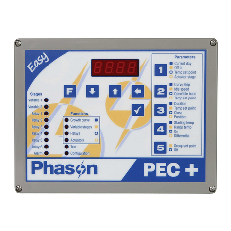
ERS AK 6000 User manual

AK 6000
Maga
Wood Gasifying Boilers
Control System
User Manual
Elektronické riadiace systémy s.r.o. Polianky 18, 841 01 Bratislava www.ers.sk email: [email protected] Tel: 421 2 693 07 000

AK6000 - prevádzkový manuál
This document is intended for use with AK6000 –the electronic system for wood gasyfying
boilers control.
AK6000.X
The modular electronic control system for wood gasyfying heat-water or heat-air boilers. On
the basis of the choosed program effectively optimizes combustion procesess so the boiler is
able to generate appropriate medium in heating system. Indication .X means hardware
version of the AK6000 where X may be within 0 ÷ 3.
DUOLED
Double color light emitting diode used to show main state of the boiler.
Display
Grafic LCD display with 128x64 pixel, LED backlight.
Flash memory
Electrically Erasable Programmable Read Only Memory to preserve data even after
shutdown.
RWM
Read Write Memory is intended to save continuously processed data. They are erased after
shutdown.
AKBUS
System Bus connects modules of the AK3000 and provides powering and communication by
means of RS485 bus and other specialized signals.
Specification
Terminology

AK6000 - prevádzkový manuál
!
Warning - danger or risk of injury
!Important note or statement
Please read these instructions carefully before using the AK6000 control unit
Do not use the boiler until completely installed
When the boiler is ON you can not do the following
oremove enclosure from the electrical parts - for example electronic modules,
fans, sensors, thermostat etc.
oreplace the fuses
orepair damaged cables and modules etc.
Before removing the cover of the electrical parts or other apliances is important to
disconect the power cord from the AC outlet.
Do not operate the boiler unless all enclosure panels are properly in place
In case of failure detection or damaging any part is important
odo not touch any part of boiler
oimmediately disconect boiler out of the AC outlet
orefer all servicing to qualified service personnel
This appliance is not suitable for person which were not instructed by the responsible
operator for using the appliance or whose have physical and other disability which
prevents from the safe operation on the apliances
!
Improper connection of the equipment can result in risk of electric shock. Check with
qualified electrician or service representative if you are in doubt whether the boiler is properly
Safety Instructions
Important Symbols

AK6000 - prevádzkový manuál
This automatic system is intended to control the producing of heat-water or heat-air in wood gasyfying boilers. Basic principle of the
function is regulation of the water temperature by means of setting the amount primary air in combustion fireplace of boiler.
Supply of air is controlled by continous influence to the suction fan operating speed.
Two electronic modules create basic composition of the AK6000.0
AK6000D –Control Unit
AK5000S –Power Board
Grafic LCD display, 128x64 pixel, LED backligt
Two level power source 230VAC / 24 and 9 VDC
Five point touch-button
Two fan outputs - main fan and auxiliary fan
Duo LED ( red / green )
Water-pump output
20 pin connector to connect power board
Four temperature sensors T1..T4
! Two independent fuses F1,2/0,8A save system parts and fans in malfunction
Adjusting boiler by means of the LCD display, signal DuoLED and five
arrow button
Water temperature PID control in adjustable range 60 ÷ 85 °C by means
of the continuous regulation of the fan
Water pump switching in pulse mode provides suppresion of the low-
temperature corrosion
Two temperature sensors connection option: T1 (water sensor) and T2
(combustion sensor)
Emergency heat thermostat conecting option
It is possible to expand the basic configuration by Lambda-probe board or Ethernet board for remote control.
CONTROL SYSTEM CONFIGURATION
Basic Configuration AK6000.0
Basic Configuration Functions AK6000.0

AK6000 - prevádzkový manuál
- graphic display, 128 x 64 pixels, LED backlight for getting
information
- duoLED –total status OK ( green ) / Err ( red )
- button ▲- increasing adjusted value or switching depiction of
the measured values
button ◄- auxiliary fan power down or move the selection left
- button ►- choice back (ESC ) or move the selection right
- button ENTER
oshort pressing
power on the boiler, five arrow button depiction and subsequently you can power off boiler or
supply fuel ( suction fan goes to 100% )
fuel suply ending - after fuel suply is passed by
menu level or choice confirmation, data storage
olong ( 2 sec ) pressing –entrance to user operation settings
- button - decreasing adjusted value or switching depiction of the measured values
- current time
- boiler thermometer is installed
- power value of the boiler (16 –80kW)
- actual status of the boiler OFF/ON/END/boiler temp.
- combustion thermometer is installed
- water pump status –sign is flashing when water pump is ON
- boiler temperature –user depiction –it can be switched by ▲or button to next value
- boiler dealer
- current date
- combustion temperature
- instant speed of the main fan
GUIDE TO THE CONTROL UNIT
Operating Points AK6000.X
Operating Screen AK6000.X

AK3000 –User Manual
Boiler is OFF
Short pressing of the ENTER turns the boiler ON.
Long pressing of the ENTER gets the operator into the parameter settings
Start of the heating
Fan is working with 100% top speed
We can turn OFF the boiler by pressing ENTER and ◄subsequently
After the combustion temperature reaches value end+20°C in 30 minutes
long time interval the boiler is in combustion process otherwise the boiler turns off ( END status )
Water pump power ON
Water pump is working in pulse status first and then in permanent status
Boiler is prepared to fuel supply by means of the double pressing of the
ENTER( function ) –main fan goes to 100% top speed in suction
version or to 0% in blower version
Combustion
Continuous regulation of the fan keeps the boiler temperature on the acquired
value
Critical values of temperatures and thermostat automatic monitoring
Boiler maximal temperature overrun
Capture of the boiler max. temperature overrun ( T max = T requested + 10°C) or
at Tmax = 90°C
Fan power OFF. Back from MAX state gets boiler after decreasing under the
requested temperature.
Heating gets weaker
Top speed of the fan (100%) cannot reach requested temperature for long time
Combustion temperature falls despite the top speed (100%) of the fan for long
time
Fuel supply is necessary
Basic Modes AK6000.X

AK3000 –User Manual
Fuel supply
Double click of the button ENTER ( function ) prepares the boiler to fuel
supply–main fan goes to 100% top speed in suction version or to 0% in blower version
Door opening
Wait 10 seconds after door is depicted on the display - fan will absorb the
combustion
Open the door and make all required action
Short press the ENTER–boiler gets in original state again
End of the combustion
Combustion temperature decreases under the minimal value –boiler is
automatically turned OFF
Fuel supply and boiler turning ON is necessary
Water pump is OFF
Basic Characteristics AK6000.X

AK3000 –User Manual
Boiler is turned ON by connecting the power cord into the AC outlet. In 10 seconds will the basic view displayed
Basic view
Starting at basic view we must hold the button ENTER two seconds long:
Basic view goes to the frame 1 where we use short click on the ENTER and we are in the frame 1.1. Short click of the
ENTER and we can set required temperature by buttons ▲or in 70 –85 °C range. Short click of the ENTER
confirms choosed value and frame 1.1 we leave by double click of the ►( ESC ).
OPERATING
Starting AK6000.X
Required Boiler Temperature Setup AK6000.X

AK3000 –User Manual
Starting at basic view we must hold the button ENTER two seconds long:
Basic view goes to the frame 1 where we use button ▲till we get to the frame 2. Short click on the ENTER and we are in
the frame 2.1. One more time click on the ENTER and we get to the frame 2.1.1. Using buttons ▲or we can choose
required parameter:
Frame 2.1.1 we can leave by double click of the ►( ESC ).
Combustion upper temperature –increase over of this value limits speed of
the fan. It provides chimney protection.
130 - 280°C
Combustion lower temperature –decrease under of this value activates
boiler status END –fuel burnout. It keeps the embers waiting.
50 - 130°C
Main fan power change. For example: value -3 decreases fan speed in 30%
-3, -2, ... 2, 3
Fan minimal speed. This value is limit for speed decrease of the fan after
reaching requested boiler temperature.
0 –70%
LCD display brightness
0 - 128
Roling of the values in user depiction on the basic view of the display.
yes / no
Time to display help of five arrrov button in frame 2.1.1
0 –10 s
Ventilation in combustion chamber –this time interval of the 100%
fan speed is switched every 60 seconds after overrun the required
boiler temperature
0 –300 s
Time to reach END status after decreasing the combustion
temperature below end value
0 –60 min
Temperature scale set up.
°C ( Celsius ) / °F ( Fahrenheit )
Automatic change of winter and summer time.
yes / no
User Parameter Setup AK6000.X

AK3000 –User Manual
Starting at basic view we must hold the button ENTER two seconds long:
Basic view goes to the frame 1 where we double use button ▲till we get to the frame 3. Short click on the ENTER and we
are in the frame 3.1. Using buttons ▲or or ENTER we can make required parameter to flash. Using buttons ▲or we
set flashed value to required time or date. Choice is stored by the ENTER and so we move to next position we want to
change. Frame 3.1 we can leave by double click of the ►( ESC ).
All the connected accsesories are monitored by system. Common error status is displayed by red color of the LED. More exactly
is error message displayed on the LCD display in the failure frame 4.
Starting at basic view we must hold the button ENTER two seconds long. Triple click on the buttons ▲or will get us to the
frame 4. One click on the ENTER displays first failure, if any. Next failures we can display by the button▲.
Disconnecting of thermometers T1 ( boiler temperature ) or T2 ( combustion temperature ) is on the next views:
Frame 4.1 we can leave by double click of the ►( ESC ).
Current Time Setup AK6000.X
Error messages AK6000.X

AK3000 –User Manual
Sotware implemented in hardware modules we can verify in frame 6 „Info“. We can see a version and date with exact time of
software generation here.
Starting at basic view we must hold the button ENTER two seconds long. One click on the button will get us to the frame 6.
By means of the ENTER button we can enter into the version display:
.....
By means of the ENTER button we can display the current software version of the AK6000D module:
...
Frame 6.1.1 we can leave by triple click of the ►( ESC ).
We can use service parameter setup 1 to configurate basic properties of the connected components.
!
Improper setup of service parameters can result in risk of boiler incorrect behaviour
or damaging some amount of boiler. Just the qualified service representative can properly
act in this area.
You need to TURN OFF the boiler before setting in this area.
Starting at basic view we must hold the button ENTER two seconds long. One click on the button▲will get us to the frame2.
We can hold the ◄button for two seconds and more now. A frame with request for service PIN will be displayed:
Version of software AK6000.X
Service Parameter Setup 1 AK6000.X

AK3000 –User Manual
By means of the ▲or we can set the first flashing digit of the PIN xxxx and by ENTER button we confirm it. So we can
enter rest of the PIN. With ENTER button we can get to the frame 2.8.1.1. :
Using buttons ▲or we can choose required parameter then by means of ENTER button confirm and flashing parameter
is able to change by ▲or buttons:
......
Frame 2.8.1.1 we can leave by click of the ►( ESC ). Parameter is set now.
Boiler type. Numeric value represents power of the boiler and L character
is for Lambda module connected. Caution! Parameter setup can
change related parameters.
XY16, XY16L,....XY100,
XY100L etc.
Main fan is suction type. We can change it to the blower type.
or
Combustion thermometer is installed. Boiler reaches END status after
decreasing the combustion temperature below end value.
yes / no
Auxiliary fan is not connected.
yes / no
Boiler thermometer is installed with KTY type. You can change it to the Pt1000.
KTY / Pt1000

AK3000 –User Manual
We can use service parameter setup 2 to configurate chosen „hardware“ properties of control unit.
!
Improper setup of service parameters can result in risk of boiler incorrect behaviour
or damaging some amount of boiler. Just the qualified service can properly act in this area.
You need to TURN OFF the boiler before setting in this area.
Starting at basic view we must hold the button ENTER two seconds long. One click on the button▲will get us to the frame2.
We can hold the ◄button for two seconds and more now. A frame with request for service PIN will be displayed:
By means of the ▲or we can set the first flashing digit of the PIN yyyy and by ENTER button we confirm it. So we can
enter rest of the PIN. With ENTER button we can get to the frame 2.9.1. :
Using buttons ▲or we can choose required parameter then by means of ENTER button confirm and flashing parameter
is able to change by ▲or buttons:
......
Frame 2.9.1 we can leave by click of the ►( ESC ). Parameter is set now.
Secondary servodrive S1 valve in Lambda module. It means end position of close
movement.
0-100%
Min. switching value for triac of the main fan.
0,25 –0,99
Max. switching value for triac of the main fan.
0,25 –0,99
Display contrast
0 - 40
Service Parameter Setup 2 AK6000.X

AK3000 –User Manual
In this section we can manually activate connected components as fans or water pump for service purpose.
!
Improper setup of service parameters can result in risk of boiler incorrect behaviour
or damaging some amount of boiler. Just the qualified service can properly act in this area.
You need to TURN OFF the boiler before setting in this area.
Starting at basic view we must hold the button ENTER two seconds long. One click on the button▲will get us to the frame2.
By means of the ▲or we can set the first flashing digit of the PIN xxxx and by ENTER button we confirm it. So we can
enter rest of the PIN. With ENTER button we can get to the frame 2.8. Subsequently by means of the ▲and ENTER
button we can depict frame 2.8.15 with set of outputs:
Using buttons ▲or we can choose required output then by means of ENTER button to turn it ON or OFF:
Output –main fan is OFF
ON / OFF
Output –auxiliary fan is OFF
ON / OFF
Output –water pump is OFF
ON / OFF
Output –OPEN secondary servodrive is OFF
ON / OFF
Output –CLOSE secondary servodrive is OFF
ON / OFF
Inicialization secondary servodrive is OFF
ON / OFF
Output –expander relay 1 is OFF
ON / OFF
Output –expander relay 2 is OFF.
ON / OFF
Output –expander relay 3 is OFF
ON / OFF
Component Service Activation AK6000.X

AK6000D
Input voltage
7,5VDC
Input current
0,06A
Operating temperature
max 45°C
Case
IP20
Connection with AK5000S
20-pin conector PFL
AK5000S
Input voltage
230VAC, 50Hz ±10%
cord 3m, H05VV-F 3Gx0,75, PVC, temperature range -15 až +70°C
Full load
1,6A
Temperature range
max 45°C
Case
IP00
Component terminals
Fan / Pump : 0,75mm², T1-T4 : 0,5 mm²
Maximum number of inputs
3
Boiler thermometer
KTY ( PTC / polovodič, R=2kOhm/20°C )
Combustion thermometer
PT1000
Crash thermostat
Contact Normally Closed
Maximum number of outputs
3
Main fan
230VAC / 0,4 A
Auxiliary fan
230VAC / 0,4 A
Water pump
230VAC / 0,8 A
Fuse F1 –Main and auxiliary fan
0,8 A, T 5x20mm
Fuse F2 –Control unit and water pump
0,8 A, T 5x20mm
Electric Parameters AK6000.X

AK3000 –User Manual
BLOCK DIAGRAM AK6000.X
Table of contents
Popular Control System manuals by other brands
Elstat
Elstat ems25 Series product manual
ABB
ABB REC670 2.1 IEC Product guide
ONEFINITY
ONEFINITY Elite Series Installation and operation instruction
Extron electronics
Extron electronics TouchLink TLC Pro 526M Series user guide
Toshiba
Toshiba TOSDIC-CIE DS Installation and wiring manual
SYR
SYR BA-Filling-Combi 6628 Instructions for use and installation
