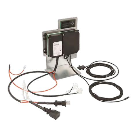
Elstat ems25 Series User manual

ems25+
ems25 advanced
PRODUCT MANUAL
Firmware: U02 - n01 - ems25+
Firmware: U03 - n02 - ems25advanced

www.elstat.io
Copyright © Elstat Ltd
2020 All Rights Reserved
All information in this document is
property of Elstat Ltd
Commercial use and distribution
of the contents of this publication
is not allowed without express and
prior written consent of Elstat Ltd

CONTENTS
1 ems controller reference guide 1
1.1 About this reference guide 1
2 What is the ems25 series? 2
2.1 Water ingress - advisory information for FMEA analysis 3
2.2 ems25+ and ems25advanced user interface 3
2.3 environmental ratings 4
2.4 ems25 series relay ratings 4
2.5 ems25+ wiring diagram 5
2.6 ems25 series thermal fuse (CQC only) 6
2.7 ems25advanced wiring diagram 7
2.8 How to mount ems25 series controllers 8
3 Temperature input ranges 10
3.1 How to mount the appliance sensor 10
3.2 How to mount the evaporator sensor 11
3.3 How to mount the condenser sensor 11
4 Door Switch 12
4.1 How to mount the door switch 12
4.2 How to mount the enhanced door switch 13
4.3 How to mount door switches on double-door coolers 14
5 ems controller functionality 15
5.1 Product temperature 15
5.2 Activity 16
5.3 Ready mode 16
5.4 Saving mode 17
5.5 Teach 18
5.6 Teach 18
5.7 Defrost on Glass DOor Coolers (GDC) 19
5.8 Freeze-up protection 19
5.9 Compressor management 20
5.10 Lights management 21
5.11 Alarms 21

6 Self-learning 22
6.1 What is the self-learning matrix? 23
6.2 How a 7-day learning period works 24
6.3 How a 1-day learning period works 25
6.4 How the self-learning matrix updates after the learning period 27
6.5 How ems controllers switch between ready and saving modes 28
7 User Guide 29
7.1 Power up sequence 29
7.2 Display codes 30
7.3 How to access the menu (example) 32
7.4 How to access the menu 33
7.5 How to view the ems25+ parameter settings (PS) 34
7.6 How to view the ems25advanced parameter settings (PS) 36
7.7 How to run the test routine (tst) 38
7.8 How to perform a half reset (Hr) 40
7.9 How to view the last three alarms (Flt) 41
7.10 Statistics 42
7.11 How to view statistics 42
8 Troubleshooting 44
8.1 How to check that ems controllers are working correctly 45
8.2 How to troubleshoot condenser high temperature (HT) alarms 45
8.3 How to troubleshoot door alarms (door switch fitted) 46
8.4 How to troubleshoot door alarms (no door switch fitted) 47
8.5 How to troubleshoot motion sensor alarms 48
8.6 How to troubleshoot refrigeration system failure (rSF) alarms 48
8.7 How to troubleshoot temperature sensor alarms 50
8.8 How to troubleshoot problems with freeze-up protection (888) 51
8.9 How to troubleshoot not cooling problems 51
9 elstat parameter loader 52
9.1 What are the xml files? 52
9.2 What are checksums? 53
9.3 Parameter programming accessories 53

9.4 How to install the drivers on Windows XP 54
9.5 How to install the parameter loader 56
9.6 How to start the parameter loader 58
9.7 How to connect the docking cradle 58
9.8 How to configure the COM port 59
9.9 How to load the parameter settings 61
9.10 How to view the download counter 62
9.11 How to view the version of the parameter programming tool
(dongle)
62
9.12 Display codes for parameter downloads 63
10 Parameter reference 64
10.1 Parameters by function 64
10.2 Parameters by owners 65
10.3 Temperature setting rules 65
10.4 Alarm delay (Ad) 66
10.5 Activity frequency (AF) 66
10.6 Marketing mode (Ar) 67
10.7 Buzzer enable (b0) 68
10.8 Buzzer duration (b1) 68
10.9 Calibration 1 (CA1) 69
10.10 Celcius or Farenheit (CF) 69
10.11 Refrigeration system failure (Ct) 70
10.12 Display stability (d2) 70
10.13 Defrost duration (dd) 71
10.14 Defrost interval (dE) 71
10.15 Differential (dIF) 72
10.16 Display (dIS) 72
10.17 Delay to saving (dS) 73
10.18 Defrost termination temperature (dtd) 73
10.19 Frezz-up protection (dtt) 74
10.20 Fan cycle off (FCF) 74
10.21 Fan cycle on (FCO) 75

10.22 Fan set point (FSP) 75
10.23 Condenser high temperature (Ht) 76
10.24 Uninterrupted pull down (IPd) 76
10.25 Lights delay (Ld) 77
10.26 Learning period (LP) 77
10.27 Saving temperature disable (PEr) 78
10.28 Compressor rest time (rt) 78
10.29 Saving differential (Sd) 79
10.30 Motion sensor enable (Sn) 79
10.31 Set point (SPC of SPF) 80
10.32 Saving restart period (Sr) 80
10.33 Saving set point (SSO 81
11 Annex | UL information 82
11.1 ems25+ rear view (input reference) 82
11.2 Additional information 83
12 Technical data ems25+ 84
12.1 Dimensional drawings 84
12.2 Controller relays 84
12.3 Temperature sensors 84
12.4 Environmentat ratings 85
12.5 Product approvals 85
13 Technical data ems25advanced 86
14 ems decorative trims 88
14.1 Small decoratve trim kit 88
14.2 Fitting the small decorative trim kit 88
14.3 Large decorative trim kits 90
14.4 Fitting the large decorative trim - with remote motion sensor 91
14.5 Fitting the large decorative trim - without remote motion
sensor
91

1www.elstat.io
1. OVERVIEW
ems (energy managementsystem)controllers from elstatare usedinavariety of drinks coolers, optimisingenergy
savings, withoutcompromisingondrinks servingtemperature.
Arange of controllers are available to suit applications such as:
• Singledoorcoolers
• Doubledoorcoolers
• Openfrontcoolers
• Vendingmachines
• Sub-zerobeercoolers
1.1 About this reference guide
The purpose of this guide is toexplainindetail all informationregardingelstatcontrollers includingthe user interface,
parameters, accessories andtroubleshooting.
Complimentary informationis alsoavailable from elstatsuchas accessory lists, accessory datasheets andsingle shee-
tuser guides.

www.elstat.io 2
The ems25 series consists of the ems25, ems25+, and ems25advanced. The ems25 series is designed as a compact
alternative the ems55 series.
2. What is the ems25 series?
Feature Desicription
User and diagnositc information
3-digit, 7-segment display (ems25+ and ems25advanced only) and push
buttons that display the product temperature and other information such
as defrost or teach and alarm conditions. Also, enables end-users to cancel
alarms and service technicians to run test routines.
Product temperature
An appliance sensor measures temperature of the refrigeration
compartment. ems controllers use the refrigeration temperature to manage
the product temperature.
Refrigeration system high
temperature alarm
An optional condenser sensor measures the temperature of the refrigeration
system. ems controllers use the temperature to alert to problems such as
blocked condensers. ems25+ and ems25advanced only.
Motion detection A remote motion sensor enables ems controllers to detect activity when
someone moves in frontof the cooler.
Door open detection Adoor switch enables ems controllers to detectcooler activity when
someone opens the cooler doors.
The ems25 series with the suitable accessories also provide the following functionality:
The ems25 series controllers switch the following cooler components:
Feature Desicription
Compressor ems controllers switch the compressor to manage the temperatire of the
refrigeration compartment
Evaporator fan ems controllers switch the evaporator fan to manage the evaporator fan.
ems25advanced only.
Lights ems controllers switch the cooler lights to save energy.

3www.elstat.io
2.1 Water ingress–advisory informationforF MEA analysis
Elstat products have been designed to minimise any risks associated with water ingress and all controllers are IPX5
certified.
The OEM or installer is responsible to ensure that local/country laws andregulatory requirements are met.
2.2 ems25+ andems25advanced userinterface
The user interface of the ems25+ and ems25advanced is as follows:
Indicator Functon Colour
1Saving temperature
disable
on if the saving mode temperature is disabled.
The controller maintains ready mode temperature at all times Red
2 Motion on when motion is detected Red
3 Compressor on when the compressor is running Green
The ems controller buttons access the menu to view parameter values, reset the ems controller, and to run test
routines.
Push buttons:
Button Name Functon
defrost
or
teach
ems25advanced: starts a defrost cycle.
ems25+: sets the ems controller to the daving mode for up to one
hour.
Set Selects menu options and scrolls through the parameters
Up Increases the parameter values.
ems25+: Also exits the tech saving mode
Down Scrolls down menus, decreases parameter values, and cancels
alarms

www.elstat.io 4
2.3 Environmental ratings
Characteristic Value
IP rating IPX5
Maximum operatiing temperature 55°C (131°F)
Minimum operating temperature 0°C (32°F)
Housing material Black polycarbonate
The table below details the general characteristics of the ems25 series.
2.4 ems25 series relay ratings
ems25+ maximum IECrating@100-240VAC maximum ULratings @ 120VAC
Compressor 6(6)A, p.f.0.6 6 FLA, 36 LRA
Lights 2(2)A, p.f.0.6 120VAC, 60Hz, 250W florescent
Evaporator fan not applicable not applicable
The table below details the relay ratings of ems25+ controllers
ems25+ maximum IECrating@100-240VAC maximum ULratings @ 120VAC
Compressor 10(10)A, p.f.0.
not applicable
Lights 10(10)A, p.f.0.
Evaporator fan 4(4)A, p.f.0.6
The table below details the relay ratings of ems25advanced controllers

5www.elstat.io
2.5 ems25+ wiring diagram
The wiring diagram for the ems25+:
Drip loops must be made in all cables
Note
For security, once fitted, the rear cover can only be removed using a tool, such as a small, flat
bladed screwdriver.

www.elstat.io 6
2.6 ems25 series thermal fuse (CQC only)
The ems25 andems25+ housings are designed with
an aperture for athermal fuse tobe located.
The thermal fuse is apartof a main harness which is
supplied by elstat.
The location for the 4-way mains connector
(harness) and thermal fuse are shown in the
diagram to the right:
Fit the connector into the port, and the thermal
fuse into the aperture, ensuring that it is fully
enclosed:
Make sure that the connector has ‘clicked’ into
place and the connection is sound.
Check that the thermal fuse is fully protected
within the aperture.
The aperture has been designed specifically for the
thermal fuse supplied by elstat.
Do not use the aperture for any other purpose.
All cables mustexitvertically, as shown in the
diagram to the right
Drip loops must be made in all cables
Note
For security, once fitted, the rear cover can only be removed using a tool, such as a small, flat
bladed screwdriver.

7www.elstat.io
2.7 ems25advanced wiring diagram
Drip loops must be made in all cables
Note
For security, once fitted, the rear cover can only be removed using a tool, such as a small, flat
bladed screwdriver.
The wiring diagram for the ems25advanced:

www.elstat.io 8
Note
The ems25 seriesc ontrollers must not be exposed to temperatures greater than 55°C (131°F) or
lower than 0°C (32°F).
2.8 How to mount ems25 series controllers
ems25 series controllers have an IP (Ingress Protection) rating of IP45. That is, the ems controller has protection
against water jets. Anappropriate level of protection must be given for the effects of water ingress due to water
jetting, condensation, product spillage, and so on.
Before beginning installation, remove all protective film from between the rear seals of the controller. The seals are
malleable, to ensure a water resistant seal around cables and prevent water ingress.
ems25 series controllers are designed for panel
mounting. The panel aperture dimensions are
shown to the right.
To mount an ems25 series controller, insert the
ems controller into the aperture as shown in the
example to the right.
Then, secure the ems controller into position using
the supplied display side-clips as shown to the
right.
Note
Decorative trim kits are supplied separately. See ‘ems decorative trims’ on page 88 The Large
decorative trim kits are screwed into place

9www.elstat.io
Note
Cable routing looms must not be secured to hot pipes or vibrating components.
Secure cable routing looms with clips whereever possible.
For security, once fitted, the rear cover can only be removed using atool,such as a small, flat
bladed screwdriver.
Cable routing to the ems controller is critical as
water can trace or follow the cable downwards.
Therefore, immediately prior to the connection to
the controller, a drip loop must be formed in all
wiring as shown to the right

www.elstat.io 10
3. Temperature input ranges
Sensor Input range (°C) Input range (°F)
Appliance sensor -10°C to 23.3°C
+/- 0.5°C
-14°F to 74°F
+/- 1°F
Condenser sensor
(not used with R744 coolers)
50°C to 125°C
+/- 5°C
122°F to 257°F
+/- 10°F
The table below shows the temperature input ranges of the ems25 series controllers for eachsensor type
Note
The NTC thermistor from elstat is rated at -35ºC to 125ºC (-31ºF to 257ºF).
3.1 How to mount the appliance sensor
The appliance sensor measures air temperature of
the refrigerated compartment by measuring the
return air temperature.
The diagram to the right shows the recommended
position of the appliance sensor. The appliance
sensor measures the air temperature after the air
has been drawn over the products.
The returnair provides a close approximation of the
product temperature.
To measure the return air temperature, secure the
sensor to allow air to flow over the sensor head.
The sensor head should be placed at a right-angle
to the air flow and secured usinga P-clip.
The sensor head should not be completely covered
by the P-clip or the sensor will not function
correctly.
Note
The sensor head is fragile and can easily be damaged.Using cable ties to secure the sensor
head or sensor cable is not recommended and invalidates the warranty.
Note
To help place the appliance sensor, the parameter calibration1 (CA1) defines an offset
temperature. See “Calibration” 1 (CAT1)”.

11 www.elstat.io
3.2 How to mount the evaporator sensor
The evaporator sensor measures the temperature
of the evaporator. ems controllers use the
temperature of the evaporator to activate and
terminate defrost cycles.
The evaporator sensor should be placed in the
immediate proximity of the evaporator.
Mount the sensor head inside the evaporator
cooling fins, as shown below.
The sensor head must be mounted securely to
prevent being dislodged due to vibration.
For coolers fitted with a defrost heater, the
evaporator sensor should be placed as far away
as possible from the heating element, i.e. at the
opposite end of the evaporator.
If the evaporator sensor measures the localized heating from the heating element, defrost cycles will terminate
before the whole evaporator has had the opportunity to defrost.
Note
Do not use cable ties.
The head of the sensor is fragile and can be easily damaged.Using cable ties to secure the
sensor head, or sensor cable, invalidates the warranty.
3.3 How to mount the condensor sensor
This sensor measures the temperature of the refrigeration system. Excessive condenser temperature is usually due
to poor preventive maintenance, i.e poorly cleaned condenser, or condenser fan failure.
For example, fix using a metal pipe clip or direct fitting, as shown below. Elstat can supply pipe clips for 6-8mm and
8-10mm pipes.
Note
Do not use cable ties.
The head of the sensor is fragile and can be easily damaged.Using cable ties to secure the
sensor head, or sensor cable, invalidates the warranty.
Do not attach sensor cables to hot pipes or allow the sensor cables to come into contact with
hot pipes.

www.elstat.io 12
4. Door switch
Door switches are used to detect door openings. Door switches are safety extralow voltage (SELV) components that
are able to create an open and closed circuit.
The enhanced door switch, and activator, are SELVcomponents, over-moulded for strengthened physical protection
and resistance to water ingress, and create an open and closed circuit.
Enhanced door switches must be used with enhanced activators.
Enhanced door switches are available from Elstat in various lengths.
4.1 How to mount the door switch
Door switches are usually mounted with the door
switch on the cooler and the activator on the door.
Door switches and activators must be fixed using
counter sunk screws or bolts with the following
characteristics:
• Head: countersunk head maximum diameter
5.0mm (0.24in)
• Thread: maximum diameter 3.0mm (0.16in)
The screws must be tightened to a maximum torque of 0.5Nm (0.37lbfft).
Note
Door switches and activators supplied by elstat must not be installed using rivets. Using rivets
invalidates the warranty.
Alignment Dimensions Notes
XHorizontal 0mm (0in) +/-20mm (0.7in) measured when the door is closed and
the gap (z-dimension) is correct
Y Vertical 0mm (0in) +/-10mm (0.4in)
Z Gap 0mm (0in) to 5mm (0.2in) +/-2mm
(0.07in)
The alignment of the door switch and activator is critical for the correct operation of the door switch. The following
table details alignment tolerances.

13 www.elstat.io
The diagram shows the horizontal, vertical, and gap alignment between the door switch and the activator for open
and closed doors.
4.2 How to mount the enhanced door switch
Door switches are usually mounted with the door switch
on the cooler and the activator on the door. Door switches
and activators must be fixed using counter sunk screws
or bolts with the following characteristics:
• Head: countersunk head maximum diameter 6.0mm
(0.236in) and minimum diameter 5.0mm (0.196in)
• Thread: maximum diameter 3.0mm (0.118in)
The screws must be tightened to a maximum torque of
0.5Nm (0.37lbfft).
Alignment Dimensions Notes
XHorizontal 0mm (0in) +/-20mm (0.7in) measured when the door is closed and
the gap (z-dimension) is correct
Y Vertical 0mm (0in) +/-10mm (0.4in)
Z Gap 0mm (0in) to 5mm (0.2in) +/-2mm
(0.07in)
The alignment of the door switch and activator is critical for the correct operation of the door switch. The following
table details alignment tolerances.
Note
Door switches and activators supplied by elstat must not be installed using rivets. Using rivets
invalidates the warranty.

www.elstat.io 14
4.3 How to mount door switches on double-door coolers
For double-door coolers, two door switches must be connected in
series.
Connect two door switches in series as follows:
1. Remove the two wires from one of the connectors. Be careful not to
damage the terminals.
2. Remove the white wire from the second connector.Again, be
careful not to damage the terminal.
3. Insert the white wire of the first cable into the connector of the
second cable ensuring that the terminal is in the correct orientation.
4. Connect the red wire from the first cable and the white wire from
the second cable together using a butt splice or similar.
The image on the right shows two door switches connected in series.
This manual suits for next models
2
Table of contents
Other Elstat Control System manuals
Popular Control System manuals by other brands
INIM Electronics
INIM Electronics PREVIDIA MAX manual

Maxitrol
Maxitrol Mertik GV60 Installation and operating instructions

Whelen Engineering Company
Whelen Engineering Company CenCom Sapphire installation guide

Toshiba
Toshiba OIS Series user manual

Dakota Digital
Dakota Digital DHC-2000 manual

SAFEMATIC
SAFEMATIC ST-1100i manual

heat-timer
heat-timer SQ-Elite-MV Installation and operation instruction manual

Rolls-Royce
Rolls-Royce Helicon X3 user manual

Fagor
Fagor CNC 8060 manual

Aveo Systems
Aveo Systems Mira Connect 10 installation instructions

ROTOTILT
ROTOTILT ICS Translation of the original instructions

Rowe
Rowe RE3 instruction manual