Bouyer PC 1106 User manual

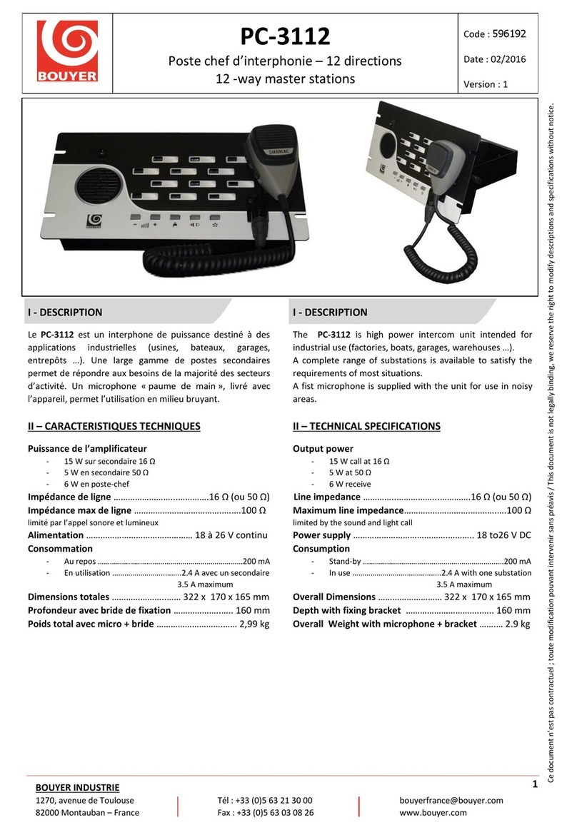
Les PC 1106 et PC 1112 sont des interphones
de puissance destinés à des applications
industrielles (usines, bateaux, garages,
entrepôts...).
Une large gamme de postes secondaires per-
met de répondre aux besoins de la majorité
des secteurs d' activité.
Un microphone "paume de main", livré avec
l'appareil, permet l'utilisation en milieu
bruyant.
L'alimentation 12 à 48 V continu ou 230 V 50
Hz en option, rendent ces appareils très poly-
valents.
•Puissan e de l’amplifi ateur
- 15 W sur secondaire 16 Ω
- 5 W sur secondaire 50 Ω
- 6 W en poste-chef
•Impédan e de ligne ............16 Ω (ou 50 Ω)
•Impédan e max. de ligne..................100 Ω
(limité par l’appel sonore et lumineux)
•Alimentation ..................12V à 48V continu
(sans commutation), + ou - à la masse.
•Consommation
-au repos ..................................................100 m A
- en utilisation ..........2,4 A avec un secondaire
3,2 A maximum
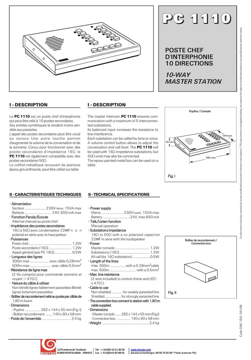
•Dimensions ................322 x 172 x 170 mm
•Poids ( avec microphone)
PC 1106 ............................................ 3,7 kg
PC 1112 ............................................ 3,9 kg
•Parti ularité
Les PC 1106 et PC 1112 peuvent être alimentés
depuis le secteur 230 V avec une alimentation
extérieure PZ 24, livrable séparément en option.
Dans le cas de l’utilisation avec le PZ 24, procéder
comme suit :
- Sur le PZ 24, couper le câble entre la prise jack
d’extrémité et la cellule de filtrage surmoulée
- Dénuder les 2 conducteurs sur 1cm environ
- Raccorder le conducteur gainé sur l’entrée + du
PC 1106 ( ou PC 1112)
- Raccorder le conducteur non gainé sur l’entrée
- du PC 1106 ( ou PC 1112).
POSTES CHEFFS DE PUISSANCE 6
ET 12 DIRECTIONS
6 AND 12-WAY HIGH POWER
MASTER STATIONS
Ce document n'est pas contractuel; toute modification pouvant intervenir sans préavis / This document is not legally binding, we reserve the right to modify descriptions and specifications without notice.
06/2011
I - DESCRIPTION I - DESCRIPTION
PP
PPCC
CC
11
1111
1100
0066
66
PP
PPCC
CC
11
1111
1111
1122
22
PP
PPZZ
ZZ
22
2244
44
The PC 1106 and PC 1112 are high power
intercom units intended for industrial use (fac-
tories, boats, garages, warehouses...).
A complete range of substations is available
to satisfy the requirements of most situations.
A fist microphone is supplied with the unit for
use in noisy areas.
With either 12 - 48 DC as standard, or using
an optionnal mains AC power supply, these
units serve a wid variety of purposes.
•Output power
- 15 W call at 16 Ω
- 5 W at 50 Ω
- 6 W receive
• Line impedan e ..................16 Ω (or 50 Ω)
• Maximum line impedan e ..............100 Ω
•Power supply ........................12 - 48 V DC
(unswitched), positive or negative earth.
• Consumption :
- stand-by ..................................................100 mA
- in use ..........................2,4 A with one substation
3,2 A maximum
•Dimensions .............. 322 x 172 x 170 mm
• Weight (incl. microphone)
PC 1106 ............................................ 3.7 kg
PC 1112 ............................................ 3.9 kg
• Feature
Both the PC 1106 and PC 1112 can be mains (230
V) powered using separate optional power supply
PZ 24.
In case of use of the PZ 24, please proceed as
following :
- On the PZ 24, cut the cable between the end
output jack and the molded filtering cell
- Strip on the 2 conductors on 1cm lenght
- Connect the sheated wire on the + input of the
PC 1102 (or PC 1112)
- Connect the unsheated wire on the - input of the
PC 1106 (or PC 1112).
II - CARACTERISTIQUES TECHNIQUES II - TECHNICAL SPECIFICATIONS

2PC 1106 - PC 1112 - PZ 24
III - PRESENTATION III - PRESENTATION
Face avant (Fig. I)
1 Interrupteur Marche/Arrêt et voyant lumineux
2 Touche “Parole / Ecoute”
Réglage de niveau de sonnerie( par tournevis)
Bouton d’appel par sonnerie
Touches de prise de ligne (6 ou 12)
3 Voyants d’appel ( 6 ou 12)
4 Etiquettes d’identification de lignes
5 Orifices pour dégagement des étiquettes
6 Vis de fixation du support microphone
Support de microphone amovible
ack (6,35 mm) du microphone extérieur
7 Mise en service du microphone "paume de main"
Réglage de volume “Parole”
Réglage de volume “Ecoute”
Face arrière (Fig. II)
15 Connecteurs postes secondaires
Connecteur alimentation et microphone
16 Serre-câbles
Verrouillage des connecteurs
18 Bride de fixation
Front panel (Fig. I)
ON/OFF switch with indicator lamp
Talk/listen button
Tone volume control (by screwdriver)
Tone call button
Channel selectors (6 or 12)
Incomming call indicator lamps (6 or 12)
Channel identification labels
Label removal slots
Fixing screw for microphone support
Detachable microphone support
ack socket (6,35 mm) for external microphone
Fist microphone switch
Speech volume control
Listen volume control
Rear panel (Fig. II)
15 Substation line connectors
Microphone and power supply connector
Cable grip
Connector retaining clips
18 Fixing bracket
1
2
10
11
12
13
14
3
4
5
6
7
8
9
IV - INSTALLATION IV - INSTALLATION
•MISE EN PLACE
Le coffret peut être soit encastré (Fig.III), soit fixé avec la fourche
orientable (Fig. II).
Les PC 1106 et PC 1112 sont livrés avec un support de micropho-
ne qui peut, au choix, être fixé sur une paroi ou sur l'appareil
par la vis (Fig.I).
• BRANCHEMENTS
Desserrer d’un demi-tour les vis sur les pièces de maintien
(Fig.II) et dégager les connecteurs.
Relier chaque poste secondaire à une des paires de plots du bor-
nier, numérotées de L1 à L12 (Fig. II). Voir section des fils préco-
nisés (Tableau Fig. V)
Si l’environnement est fortement parasité, utiliser un câble blindé,
blindage relié à , bornier .
L’alimentation continue (12V à 48V) est raccordée aux bornes +
et - indiquées sur la batterie (Fig. IV).
Le microphone peut être branché en face avant sur la prise jack
9 ou à l' arrière sur le bornier (Fig. IV).
Replacer les connecteurs conformément au repérage des éti-
quettes puis les immobiliser avec les pièces de maintien 19
Afin d'éviter l’arrachement des fils, les maintenir avec le serre-
câble .
• FITTING
The unit may be either flush mounted or fixed by its tilting bracket
(Fig. II and Fig. III).
The PC 1106 and PC 1112 are supplied with a microphone support
11 which can either be crewed to a board or fixed to the unit using
screw 12 (Fig.I).
• CONNECTIONS
Loosen the connector retaining clip screws 19 (Fig. II)
by half a turn
and remove the connectors.
Connect each substation to one of the pairs of
terminals numbered
L1 to L12 (Fig. II). See recommended cable diameters (Fig.V).
In interference is likely use screened cable connecting the screen
to on terminal strip .
The DC power supply (12 V to 48 V) is connected to the + and -
terminals indicated on terminal strip 15 .
The microphone can be connected either to the jack socket 9
on the front panel or on terminal strip on the rear panel (Fig.IV).
Replace the connectors as indicated on the labels and then secure
them using the connector retaining clip 19 . In order to avoid tug-
ging the cable, secure using cable grip 17 .
15
16
17
18
19
11
9
10
16
16
17
18
18
1
2
10
11
12
13
14
3
4
5
6
7
8
9
15
16
17
18
19
11
9
10
16
16
16
17
18
18

PC 1106 - PC 1112 - PZ 24 3
• CHOIX DES POSTES SECON-
DAIRES
Suivant le niveau sonore requis, choi-
sir les postes secondaires correspon-
dants aux conditions d'utilisation (Voir
Fig.VII).
Pour les lignes secondaires équipées
d’un haut-parleur 16 Ω , utiliser un bou-
ton poussoir d’appel et insérer dans la
ligne 2 condensateurs
électrolytiques,
en position tête-bêche (Fig. VI).
Pour une
conversation discrète avec le
poste chef, utiliser
un boîtier réponse
PS901.
Dans ce cas, couper le strap à
côté du bornier de raccordement du
PS901.
Dans les locaux très bruyants, le
casque PZ 10 (option) permet la
meilleure isolation contre le bruit. Le
PZ10se branche au PS 901.
• SELECTION OF SUBSTATIONS
According to the ambient noise level
or the area to be covered choose a
suitable substation (see Fig. VII).
When using 16 Ω loudspeaker sub-
stations, use either a call button and
insert on the line two electrolytic capa-
citors side by side (Fig VI).
To ensure discreet communication
with the master station, use a reply
unit PS 901. In this case, cut the strap
beside the PS 901 connection strip.
In areas with excessive noise, option-
nal headset PZ 10 provides better iso-
lation from external noise. The PZ 10
is connected to the PS 901. Fig. VI
Fig. V
V - UTILISATION V - USE
Mettre le poste chef sous tension 1 (Fig. I).
• POUR APPELER UN POSTE SECONDAIRE
Enfoncer la touche de ligne , et parler en pressant la touche
“Parole/Ecoute” 2 , la relâcher pour écouter. Les niveaux de volu-
me “Parole” et “Ecoute” sont réglables séparément à l’aide des
boutons et .
Il est possible de faire précéder une conversation vers les postes
secondaires d’une tonalité d’appel obtenue en pressant la touche
“Sonnerie” 5 . Son niveau est réglable par tournevis, dans
l’orifice 6 . Pour appeler ou écouter plusieurs postes simultané-
ment , enfoncer leurs touches en même temps.
Pour converser à l’aide du microphone : enfoncer sa touche de
mise en service 10 , puis effectuer l’alternat “Parole/Ecoute”
grâce à son poussoir.
Au repos, accrocher le microphone à son support 11 .
• POUR APPELER LE POSTE CHEF
Utiliser le poussoir d’appel du poste secondaire qui allumera le
voyant correspondant et déclenchera la tonalité d'appel du poste-
chef. Plusieurs appels peuvent être mémorisés simultanément au
poste chef. Le fait de maintenir enfoncée la touche de conversation
d’un poste PS 901, élimine l’utilisation du haut-parleur de puissance
auquel il est associé.
Remarque : Le fait de placer le jack d’un micro-casque dans le boîtier
PS 901 provoque automatiquement l’appel vers le poste chef.
Power up the masterstation (Fig. I ).
• TO CALL A SUBSTATION
Engage channel selector and speak while pressing talk/listen
button 4 , and release to listen. The talk and listen volume levels
are separately adjustable using buttons 7 and .
To precede a communication with a substation by a call tone,
press tone button 5 . The volume of the call tone is adjustable by
using a screwdriver in opening 6 . To call or listen to several sub-
stations simultaneously, engage the respective buttons.
To conserve using the microphone, press button 10 and, using the
switch on the microphone, press to talk,
When not in use store microphone on its support 11 .
• TO CALL THE MASTER STATION
Use substation call button which will activate the corresponding call
lamp on the master station and will activate sound the call tone.
Several calls can be memorised simultaneously by the master sta-
tion. If the speech button on the PS 901 unit remains depressed, the
loudspeaker to which it is connected is muted.
Remark :
The action of inserting the microphone headset jack plug
into the socket on the PS 901 automatically calls the master station.
5
1
5
12 12
10 10
22
44
33
13 14 13 14
1
This manual suits for next models
2
Other Bouyer Control System manuals
Popular Control System manuals by other brands

Autotrol
Autotrol Performa Ultra Operation and maintenance manual
Wintex Agro
Wintex Agro WINTEX 1000 operating instructions
Aiphone
Aiphone AC Series Quick start programming guide

Alamarin Jet
Alamarin Jet IO Operation and maintenance manual
Fike
Fike Cheetah Xi instruction manual

ENERVEX
ENERVEX BDC 8 Product information

