Erskine Attachments 1107080 User manual

Landscape Seeder
For
Skid Steer Loaders and
Compact Tractors
(SERIAL NUMBER 1107080 AND LATER)
Operator’s Manual
Maintenance
Parts Information
Read this Manual Before Use

2
SAFETY
3-4
SERIAL NUMBER/DECAL LOCATION
5-6
MOUNTING INSTRUCTIONS
7-8
OPERATING INSTRUCTIONS
9-11
ROUTINE MAINTENANCE
12-13
PARTS INFORMATION
14-26
SEED BOX CALIBRATION CHART
27
GENERAL SPECIFICATIONS
28
BOLT TORQUE INFORMATION
29
NOTES
30
WARRANTY
31
NOTE: Erskine Attachments LLC reserves the right to make
improvements in design or changes in specifications at any time
without notice and without incurring any obligations to install them on
units previously sold.
TABLE OF CONTENTS
REFERENCE INFORMATION
Write the serial number for your attachment in the space below. Always use this serial
number when calling for service or parts.
Serial Number…………..
YOUR ATTACHMENTS DEALER
ADDRESS:
PHONE:
CONTACT:

3
The user is responsible for inspecting the machine
daily, and for having parts repaired or replaced when
continued use of the machine would cause damage,
excessive wear to other parts or make the machine
unsafe for continued operation.
If an operating procedure, tool device, maintenance
or work method not specifically recommended is
used; you must satisfy yourself that it is safe for you
and others. You must also ensure that the
attachment will not be damaged or made unsafe by
the procedures you choose.
Erskine Attachments LLC cannot anticipate every
possible circumstance that might involve potential
hazard. The safety messages found in this manual
and on the machine are therefore not all inclusive.
Throughout this manual, reference may be made to
the left hand (LH) or right hand (RH) side. These
terms are used as viewed from the operator’s seat
facing front.
The signal words CAUTION, WARNING, or
DANGER are used to indicate hazards.
Indicates a potentially
hazardous situation which, if not avoided,
may result in minor or moderate injury.
Indicates a potentially
hazardous situation which, if not avoided,
could result in death or serious injury.
Indicates a potentially
hazardous situation which, if not avoided,
will result in death or serious injury.
The word IMPORTANT is used in the text when
immediate damage will occur due to improper
technique or operation.
The word NOTE is used to convey information that
is out of context with the manual text; special
information such as specifications, techniques,
reference information, and other information of a
supplementary nature.
SAFETY
DO NOT use or perform maintenanceon this machine until this manual has been
read and understood. In addition, read the Operation and Maintenance
Manual(s) pertaining to the attachment and the attachment carrier (“Tractor” or
“Loader”).

4
Improper operation can cause serious
injury or death.
Pre-operation
•This attachment is designed for drop seeding
only. NEVER use this machine for any other
purpose.
•Read the operators manual for the “Compact
Tractor” or “Skid Steer Loader”. NEVER allow
untrained people to operate.
•Operating instructions must be given to everyone
before operating this attachmentand at least once
a year thereafter in accordance with OSHA
regulations.
•Keep all shields, guards, and covers in place.
•Do not modify equipment or add attachments that
are not approved by Erskine Attachments LLC.
•Use adequate safety warning lights and devices
as required by local regulations. Obey all local
laws and regulationsregarding machineoperation
on public property.
•Only use attachment with a tractor equipped with
a Roll Over Protection System (ROPS) and
seatbelt.
SAFETY
Operation
•Avoid loose fitting clothing. Clothing caught in
moving parts may lead to serious injury or death.
•Do not exceed maximum transport speed of 15
MPH with the attachment. Reduce travel speed
when turning and when travelling on rough terrain
to prevent attachment damage or loss of control.
•Check and be sure all operating controls are in
neutral before starting the engine.
•NEVER operate near embankments or terrainthat
is so steep that rollover could occur.
•Always stay in the operator position with seatbelt
fastened when using the attachment.
•Before leaving the operators position, lower the
attachment to rest flat on the ground, stop engine,
set park brake, and wait for all motion to stop.
Maintenance
•NEVER make adjustments, lubricate, clean, or
perform any service on the machine while it is in
operation.
•Make sure the attachment is serviced on a daily
basis. Improper maintenance can cause serious
injury or death in addition to damage to the
attachment and/or your equipment.
•Before working underneath the attachment,
securely support attachment.

5
SERIAL NUMBER AND SAFETY DECAL LOCATIONS
Serial Number Location:
It is important to refer to the serial number of your attachment when making repairs or ordering parts. Early
or later models (identification made by serial number) may use different parts, or it may be necessary to use
different procedures in doing a specific operation.

6
SERIAL NUMBER AND SAFETY DECAL LOCATIONS________
Part Number: 317704
Location: On each side of seed box
Quantity: 2
Part Number: 317708
Location: On inside of chain shield
Quantity: 1
Part Number: 423252
Location: RH on inside of seed box cover
Quantity: 1
Part number: 317694 (Red reflector)
Location: On rear of seed box, each end
Quantity: 2
Part Number: 103206
Location: Under chain shield
Quantity: 1
Part Number: 422893
Location: On metering handle
Quantity: 1
Part Number: 317707
Location: Near pin parking & operating locations
Quantity: 4
Safety Decal Locations:
The locations of the safety decals are shown. If these
decals are missing, damaged, or painted over they
must be replaced. Call Erskine Attachments LLC
(218-435-4045) for replacement decals.
A
B
C
D
E
F
H
Part Number: 317706
Location: On front & rear of seed box, RH side
Quantity: 2
G
I
Part number: 300245 (Yellow reflector)
Location: On front of seed box, each end
Quantity: 2
Small Brand Decal
Location: On each end
Quantity: 2
Part Number: 501612
Location: On inside of seed box tensioner w/a
Quantity: 2
J

7
Mounting Plate Standard Position
Mounting Plate Offset Position
MOUNTING INSTRUCTIONS
After the initial set-up assembly is complete, use the following procedure to mount the attachment to the
loader for user operation.
Mounting to a Loader
1. Use the step, safety treads, and grab handles to
get on and off the loader and attachment.
2. Sitting in the operator’s seat, lower the seat bar (if
so equipped), and fasten the seat belt.
3. Drive the loader to the rear of the attachment. Put
the loader quick attach coupler into the
attachment mounting bracket.
4. Tilt the loader coupler backward a small amount
until it is fully engaged in the attachment mounting
bracket.
5. Stop the engine and engage the park brake.
6. Secure the coupler locking mechanism that
attaches the attachment to the loader.
Coupler wedges or pins must
extend through the holes in the attachment
mounting plate. Levers must be fully down
and locked. Failure to secure wedges or pins
can allow attachment to come off and cause
injury or death.
Mounting Plate Offset
The mounting plate can be offset by 5” to
accommodate loaders that are wider than 72”. Follow
the process below to offset the mounting plate:
1. Remove the two snap ring pins and slide the
mounting plate off of the hitch pins.
2. Remove the two hitch pins and reverse their
direction so that they are pointing toward the right
side of the attachment.
3. Slide the mounting plate back onto the hitch pins
and reinstall the snap ring pins to secure in place.

8
Wheel Track Remover
Spring Adjustment Holes
MOUNTING INSTRUCTIONS
After the initial set-up assembly is complete, use the following procedure to mount the attachment to the
tractor for user operation.
Mounting to a Tractor
1. Use the step, safety treads, and grab handles to
get on and off the tractor.
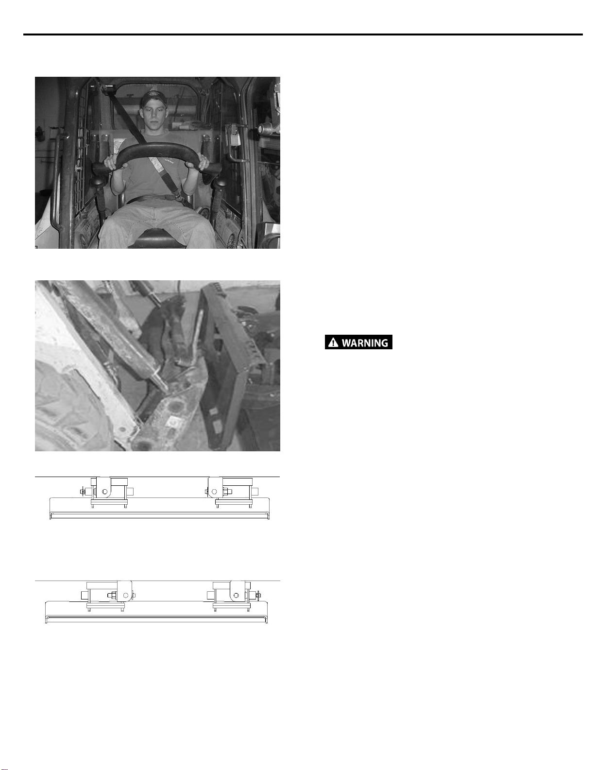
2. Sitting in the operator’s seat, fasten the seat belt
(if so equipped).
3. Drive the tractor to the front of the attachment.
Align the tractor 3-point arms with the attachment
mounting pins.
4. Stop the engine and engage the park brake.
5. Have a second person connect all 3-point links to
the attachment using the pins provided.
All appropriate hitch pins and
locking pins must be locked into place. Failure
to secure pins can allow the attachment to
disconnect from the tractor and cause injury
or death.
6. Adjust the 3-point top link so that the attachment
is level while resting on the ground (see tractor’s
operator’s manual for top link adjustment
instructions).
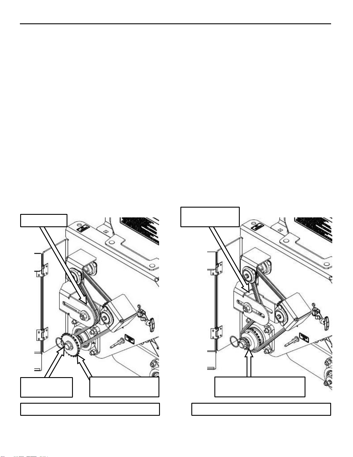
Wheel Track Remover Adjustment
1. Raise the attachment 6” to 12” off of the ground
and block in position.
To avoid being crushed, never
work on raised attachment without using
additional support blocks or jack stands.
2. Remove the 1/2" nut and lock washer from the
carriage bolt that holds the spring mount in place,
and move it to the desired depth.
3. Reinstall the nut and lock washer once the spring
mount is in place. Tighten hardware to the proper
torque (see “Bolt Torque Information” on page 29).
NOTE: Softer soil requires the wheel track
remover springs to be set deeper.

9
OPERATING INSTRUCTIONS
Seed Box Calibration
NOTE: If seed rate accuracy is important to your
application, you MUST calibrate your seeder to
ensure seed rate accuracy. The seed rate chart is
meant only as a guide.
1. Stop the engine and engage the park brake.
2. Make sure both parking pins are in the
parking/transportation positions and through the
hole in the swing arms which will keep the brake
from engaging while testing.
3. Lift the seeder 6” to 12” off of the ground and block
in position.
4. Place a tarp or some other container under the
seeder to collect the seed dropped during the test.
5. Use a 9/16” wrench or socket on the non-chain
end of the drive axle to turn the axle and agitator
over in a clockwise direction.
6. Set the meter handle to the desired position and
rotate the drive axle 48.5 revolutions.
7. Remove the tarp and weigh the seed that was
dropped by the seeder. Multiply the weight of the
dropped seed by 50 for an approximate seed
density in lbs/acre.
Seed Metering Adjustment
1. Determine the required seed density per acre or
per 1000ft2as recommended by the seed
manufacturer.
2. Use the seed box calibration chart for the specific
meter setting information. The chart decal can be
found on the inside of the seed box lid, or on page
27 of this manual.
3. The meter settings range from 0-12, where 0
indicates the gates being fully closed, and 12
indicates the gates being fully open.
4. The slide gate can be adjusted by loosening the
plastic thumb screw and sliding the metering
handle right to the number specified by the seed
box calibration chart.
NOTE: Always return the meter handle to 0 prior
to changing the seed gate to a new position. This
will ensure consistent gate settings.
NOTE: For seed types not included on the chart,
follow the “Seed Box Calibration” instructions.
Swing Arm Pinned Up

10
OPERATING INSTRUCTIONS
Idler sprocket
Idler sprocket pry
bar location
Combination 12/24
Tooth Drive Sprocket
¼” Lynch Pin &
1” Flat Washer
Combination 12/24 Tooth
Drive Sprocket Flipped Over
Drive Sprocket 12 Tooth Position
Drive Sprocket 24 Tooth Position
Doubling the Seed Rate
The seed rate can be doubled by replacing the 12 tooth drive sprocket with the 24 tooth drive sprocket.
1. Open the chain case door to allow access to the sprockets.
2. Remove the 1/4" lynch pin and 1” flat washer from the drive axle.
3. Use a 5/16” wrench to loosen the 5/8” nut on the idler sprocket and slide the idler to the left to loosen the
chain.
4. Remove the chain from the 12 tooth sprocket and remove the combination sprocket from the drive axle.
5. Flip the sprocket over and reinstall it on the driveline with the 24 tooth half first.
6. Reinstall the 1” flat washer and 1/4" lynch pin.
7. Use a pry bar to apply light force to the side of the idler sprocket and push it to the right. Apply enough
tension to the chain with the idler to remove the slack. Make sure the chain is fully seated in all three
sprockets, and tighten the 5/8” nut.
IMPORTANT: Do not overtighten the roller chain. Tighten only enough to remove slack.

11
OPERATING INSTRUCTIONS
Acre Counter Display
Loup Electronic Acre Counter
Acre Counter Adjustment
1. On the acre counter, press the FUNC button until the “PULSES” LED is lit. The number in the display
indicates how many pulses are generated per every 400 feet driven.
2. For this application, use the UP and DOWN buttons to adjust the number of pulses per 400 feet driven until
the display reads “134”.
3. Press the FUNC button until the “WIDTH” LED is lit. The number in the display indicates the width in feet
that the attachment plants per pass.
4. For this application, use the UP and DOWN buttons to adjust the planting width until the display reads “6.0”
feet.
5. For all other acre counter questions, see the Loup Electronics user’s manual that was included with the
seeder.

12
ROUTINE MAINTENANCE___________________
Lower the attachment to rest on the ground, set the park brake, shut down the engine,
remove the key, and wait for all motion to stop before leaving the operator’s seat to perform service of
any kind.
It is the operator’s responsibility to make daily inspections of the attachmentand loader/tractor for damage, loose
bolts, fluid leaks, or anything elsethat could causea potential service or safety problem. Preventive maintenance
is the easiest and least expensive type of maintenance.
IMPORTANT: Bolts and set screws can loosen after initial usage. After first hour of operation check all bolts
and set screws.
No. 2 Lithium
base gun grease
40
40
ROUTINE INSPECTION
Check the following items every 40 hours of operation:
•Check the entire attachment for weld cracks or excessive damage. Repair if necessary.
•Check all hardware. Replace or retighten if necessary.
•Check shields. Repair if damaged or replace if necessary.
•Check for damaged or missing decals. Replace if damaged or missing.
•Lubricate drive chain with an approved chain oil.
•Grease the four flange bearings using No. 2 lithium base grease gun.

13
ROUTINE MAINTENANCE___________________
Flange Bearing
Carriage Bolts
Vacuum out both sides
of the plastic idler.
Slide Gate Maintenance
After prolonged use, seed may accumulate under the seed box bearings. The excess seed may make it
difficult to adjust the seed box slide gate. To remove the excess seed:
1. Empty the seed box completely.
2. Use a 9/16” wrench to loosen the three 3/8” nuts on each of the two flange bearings.
3. Allow the bearings to slide up slightly so the plastic idlers lift away from the slide gate.
4. Move the slide gate back and forth a few times to loosen up the seed.
5. Use a vacuum to remove all of the excess seed that had built up under the plastic idlers.
6. Repeat steps 4 and 5 until the slide gate moves freely.
7. Push the bearings back down to the slide gate and retighten the 3/8” nuts.

14
LANDSCAPE SEEDER PARTS INFORMATION
ITEM
QTY
PART NO.
DESCRIPTION
STOCK NO.
1
1
317601
FRAME SEEDER 72 W/A
72"
1
424210
FRAME SEEDER 96 W/A
96"
2
1
423256
SEED BOX 72 W/A
72"
1
423258
SEED BOX 96 W/A
96"
3
1
423257
COVER SEED BOX 72 W/A
72"
1
423259
COVER SEED BOX 96 W/A
96"
4
1
317600
MOUNT FRAME SEEDER W/A
7
1
330864
HOLDER MANUAL CANISTER 12.5 X 2.25
8
4
330942
HINGE 2 X 2 HD
9
2
317703
CYLINDER GAS 7.4
10
2
13053
BOLT HEX
5/16 X 3/4 NC GR 5
11
7
37211
NUT REV LOCK
5/16 NC GR 5
14
2
317605
LATCH RUBBER 5.87 W/BRACKET
33
6
317667
RUBBER BUMPER
39
1
422891
HANDLE METERING Z
40
1
317684
HANDLE VINYL
42
1
317719
SLIDE GATE CONNECTOR W/A
44
1
423264
KNOB PLASTIC 5/16 STUD
47
1
317717
BUSH .63 X .31 X .5 AL
59
1
21813
BOLT CARRIAGE
5/16 X 1‐1/2 NC GR5
69
4
21816
BOLT CARRIAGE
3/8 X 3/4 NC GR 5 Z
75
4
33008
WASHER FLAT
3/8"
79
3
33006
WASHER FLAT
5/16"
87
1
65076
PIN COTTER 1/8 X 1
94
4
37212
NUT REV LOCK
3/8 NC
99
18
41125
RIVET 3/16 STEEL #64

15
LANDSCAPE SEEDER PARTS INFORMATION
SKID STEER SIDE

16
LANDSCAPE SEEDER PARTS INFORMATION
ITEM
QTY
PART NO.
DESCRIPTION
STOCK NO.
10
1
317600
MNTG PLATE SEEDER W/A
11
1
300460
PIN 3‐PT UPPER CAT #1 LONG
12
2
317729
MOUNT SPRING RAKE W/A
16
1
317604
3‐POINT UPPER W/A
19
2
100944
PIN 3‐PT LIFT 7/8 CAT #1
20
2
330819
PIN 3PT LIFT CAT1 7/8 & CAT2 1-1/8
21
1
420070
BUSH 1 X .78 X 1.69 Z
22
2
33012
WASHER FLAT
1/2"
23
1
420400
BUSH .75 X .53 X 2.88 Z
24
1
13218
BOLT HEX
1/2 X 3-3/4 NC GR 5
31
4
317726
SPRING HARROW LH
32
2
317731
BRKT SPRING MNT PAINTED
34
4
317727
SPRING HARROW RH
36
1
317745
METER ACRE
ACRE METER PKG
41
4
317699
PLATE STRAP PAINTED
49
5
104432
PIN LYNCH 7/16
56
4
33636
WASHER LOCK
1”
73
2
36110
NUT HEX REG
1/2 NC
74
2
33626
WASHER LOCK
1/2"
85
8
32467
BOLT FLG THRD RLNG
3/8 X 3/4 NC
86
2
318277
BOLT CARRIAGE SHORT NECK
1/2 X 1‐1/2 NC GR 5
92
9
37214
NUT REV LOCK
1/2 NC
95
8
13221
BOLT HEX
1/2 X 4‐1/4 NC GR 5
ACRE METER PACKAGE
ITEM
QTY
PART NO.
DESCRIPTION
STOCK NO.
317748
PKG ACRE METER
1
1
317745
METER ACRE
2
4
28810
SCREW MACHINE 6-32 X 5/8
(ACRE METER HDW KIT 37741)
3
4
33610
WASHER LOCK #6
(ACRE METER HDW KIT 37741)
4
1
317740
BRKT ACRE MNT ASSM PNTD
(UNPAINTED 317739)
5
2
28830
SCREW MACHINE 6-32 X 1-1/8
(ACRE METER HDW KIT 37741)
6
2
33070
WASHER FLAT SAE #6
(ACRE METER HDW KIT 37741)

17
LANDSCAPE SEEDER PARTS INFORMATION

18
LANDSCAPE SEEDER PARTS INFORMATION
ITEM
QTY
PART NO.
DESCRIPTION
STOCK NO.
8
1
423391
SHAFT HEX .88 X 76.25 W/H
72”
1
423393
SHAFT HEX .88 X 100.25 W/H
96”
13
4
317733
TAPE UHMW .022 X .5 X 71
72”
4
420303
TAPE UHMW .022 X .5 X 96
96”
22
2
424247
BRKT RETAINER SEED GATE 14.38
23
4
424246
BRKT RETAINER SEED GATE 28.38
72”
6
424246
BRKT RETAINER SEED GATE 28.38
96”
24
2
317676
BRG 5/8 3‐B FLG B‐TYPE
27
1
424240
BRKT SEED GATE 72
72”
1
424244
BRKT SEED GATE 96
96”
30
3
423299
ROTOR RUBBER 2.75 OD X 22
72”
4
423299
ROTOR RUBBER 2.75 OD X 22
96”
31
1
422876
DEFLECTOR SEED 72 W/A
72”
1
422879
DEFLECTOR SEED 96 W/A
96”
32
3
32455
BOLT THDCUT FLG 5/16 X 3/4 UNF
72”
5
32455
BOLT THDCUT FLG 5/16 X 3/4 UNF
96”
33
6
317691
PLATE RETAINER AGITATOR
72”
8
317691
PLATE RETAINER AGITATOR
96”
35
2
423394
IDLER PLASTIC 2.85 OD X 1 HEX .88
72”
3
423394
IDLER PLASTIC 2.85 OD X 1 HEX .88
96”
36
1
37406
NUT LOCK EXT TOOTH
#8-32 NC GR 5
37
1
330967
BOLT SHOULDER
3/16 X 1 (8-32) UNC
38
2
424248
IDLER PLASTIC 2.0 X 1 HEX .88
39
4
33022
WASHER FLAT USS 1”
96” ONLY
40
4
424250
PLATE WASHER 2.6 X .89 X .11 HEX Z
72”
6
424250
PLATE WASHER 2.6 X .89 X .11 HEX Z
96”
41
2
424249
IDLER PLASTIC 2.85 OD X .75 RND
72”
3
424249
IDLER PLASTIC 2.85 OD X .75 RND
96”
53
1
317648
DRIVESHAFT SEEDER METER Z
54
14
62180
RIVET 3/16 X 3/8 CLOSED
72”
22
62180
RIVET 3/16 X 3/8 CLOSED
96”
63
6
21817
BOLT CARRIAGE
3/8 X 1 NC GR 5
71
1
300251
KEY SQ 1/4 X 1
94
6
37212
NUT REV LOCK
3/8 NC
99
12
73444
BOLT SHCS 10-24 X 2 NC SS
72”
16
73444
BOLT SHCS 10-24 X 2 NC SS
96”
100
12
70924
NUT LOCK EXT TOOTH 10-24 UNC SS
72”
16
70924
NUT LOCK EXT TOOTH 10-24 UNC SS
96”

19
LANDSCAPE SEEDER PARTS INFORMATION

20
ITEM
QTY
PART NO.
DESCRIPTION
STOCK NO.
1
2
423274
SEED BOX BROADCAST TENSIONER W/A
72"
3
423274
SEED BOX BROADCAST TENSIONER W/A
96"
5
1
317606
COVER CHAIN CASE W/A
8
2
317610
HINGE 2 X 2 PIN
11
8
37211
NUT REV LOCK 5/16 NC GR 5
72"
12
37211
NUT REV LOCK 5/16 NC GR 5
96"
12
8
33006
WASHER FLAT USS 5/16
72”
12
33006
WASHER FLAT USS 5/16
96”
14
1
317605
LATCH RUBBER 5.87 W/BRACKET
25
3
317650
SHIELD PLASTIC CLEAR
72"
4
317650
SHIELD PLASTIC CLEAR
96"
26
3
317659
GASKET SIGHT GLASS
72"
4
317659
GASKET SIGHT GLASS
96"
33
2
317667
RUBBER BUMPER
38
8
21810
BOLT CARRIAGE 5/16 X 3/4 NC GR 5
72"
12
21810
BOLT CARRIAGE 5/16 X 3/4 NC GR 5
96"
54
6
62180
RIVET 3/16 X 3/8 CLOSED
72"
9
62180
RIVET 3/16 X 3/8 CLOSED
96"
59
2
330963
BOLT ELEVATOR 5/16-18 X 1-1/2 NC GR A Z
72"
3
330963
BOLT ELEVATOR 5/16-18 X 1-1/2 NC GR A Z
96"
84
2
36304
NUT HEX FULL 5/16 NC GR 5
72"
3
36304
NUT HEX FULL 5/16 NC GR 5
96"
99
10
41125
RIVET 3/16 STEEL #64
LANDSCAPE SEEDER PARTS INFORMATION
Table of contents
Popular Seeder manuals by other brands

Land Pride
Land Pride Primary Seeders PSN2096 Operator's manual

Brillion
Brillion LANDSCAPE GLP-643 Assembly instructions operator's manual

Sola
Sola VESTA-2813 NS PLUS manual

SKY Agriculture
SKY Agriculture Maxi Drill 6000 Original instructions

Earth Way
Earth Way 1001-B operating instructions

KingKutter
KingKutter S-XB Operation and parts manual