ERTE B2 User manual

B2
Weighing Indicator
User Manual

B2 WEIGHING INDICATOR
Table of contents
1 Introduction.......................................................................................................................................3
1.1 Attention Before Start................................................................................................................4
2 Interface.............................................................................................................................................
2.1 Display.......................................................................................................................................
2.2 Keypad.......................................................................................................................................6
3 Connection Diagram..........................................................................................................................7
4 Configuration.....................................................................................................................................8
4.1 Adjustment (Calibration) switch................................................................................................8
4.2 Configuration menu.................................................................................................................10
4.3 Weighing parameters................................................................................................................11
4.4 Adjustment ( Calibration ).......................................................................................................13
4. Miscellaneous Application Settings.........................................................................................14
4.6 Serial Output Settings..............................................................................................................1
Operation.........................................................................................................................................17
.1 Weighing with tare...................................................................................................................17
.2 High resolution display............................................................................................................17
.3 Multi range weighing...............................................................................................................17
6 Appendix..........................................................................................................................................18
6.1 Error messages.........................................................................................................................18
6.2 Specifications...........................................................................................................................19
v1.00 Page 2
USER MANUAL

B2 WEIGHING INDICATOR
1 Introduction
The B2 is a universal digital weighing indicator for analog load cells, which incorporates:
○Delta-sigma analog to digital converter for accurate weighing.
○nternal alibi memory for recording weighing results.
○RS-232 ports for connections to printers, remote displays, computers or other digital
terminal equipments.
○LED display.
This manual contains the information needed to configure, adjust and operate the device. To ensure
safe operation, the instructions in this manual shall be respected.
v1.00 Page 3
USER MANUAL

B2 WEIGHING INDICATOR
1.1 Attention Before Start
●Always use Earthed/Grounded Mains socket.
●Do not connect powerful electrical machines on the same mains plug.
●Disconnect mains connector before opening the enclosure.
●Recommended load cell cable cross section is 1 mm². f the cable length is too long, use multiple
wires for ±Excitation connections.
●f the sense inputs on the load cell connector are left empty, the device will display Err 3. Make sure
all the pins are connected.
●Shielded twisted-pair cables must be used for load cell and communication.
●For best accuracy, the device shall be powered on at least 30 minutes before adjustment.
●Device setup shall be performed by authorized people.
v1.00 Page 4
USER MANUAL
B2 WEIGHING INDICATOR
2 Interface
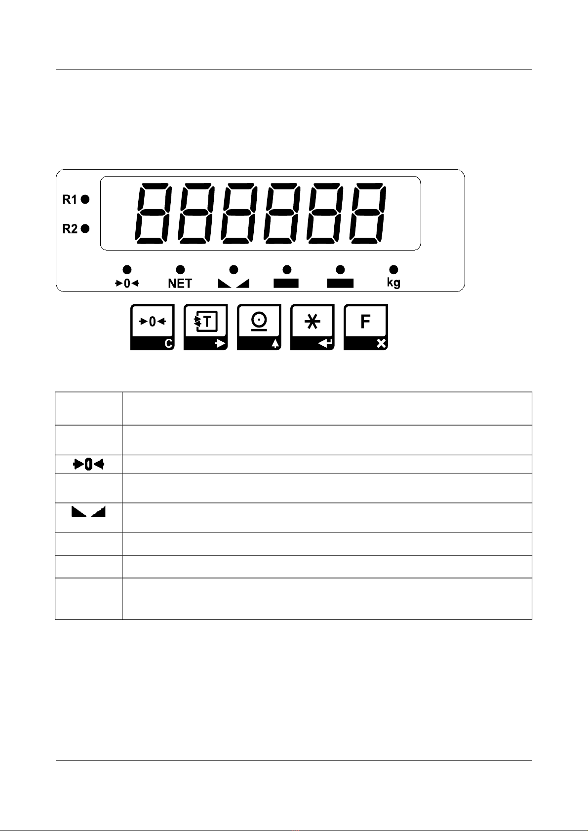
2.1 Display
Weight
display
6 digit 7-segment led display with decimal point
(Negative values are displayed with a minus sign in the leftmost digit)
R1 , R2 Range indicator: f configured as a multi range instrument, indicates the current
weighing range.
enter-of-zero indicator: ndicates the deviation from zero is not more than ±0.25 e.
NET Net indicator: ndicates that a tare device is in operation and the displayed weight
value is a net weight.
Stability (No-motion) indicator: ndicates that stability of equilibrium has been
reached.
kg Unit of weight: ndicates the unit of the weight, if a weight value is displayed.
BAT Low battery indicator: f flashing, indicates a low battery condition.
FFunction indicator: ndicates that a function is in operation and the displayed value is
a calculated value. A sticker identifying the displayed value (e.g. unit) shall be attached
here for the configured function.
v1.00 Page 5
USER MANUAL
B2 WEIGHING INDICATOR
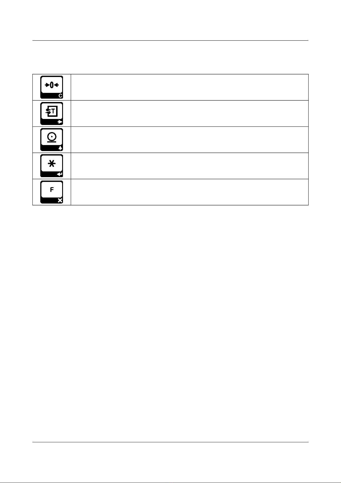
2.2 Keypad
Zero key: Set the indication to zero. Zeroing can be established only if the gross weight
is within ±2% of the maximum capacity.
Tare In / Tare Out key: f the indicated value is positive and stable, it is saved as tare
and net weight is indicated. f there is already a tare device in operation, it is cancelled
and gross weight is indicated.
Print key: f the indicated value is positive and stable it is saved as a weighing result
and a print out is produced (if configured).
Star key: Call up the configuration menu. Please refer to the configuration section.
Function key: Activates and deactivates a configured function. For a complete
explanation refer to the related section of this manual.
Note: For an explanation of the function of the keys while editing numerical values please refer to the
configuration chapter.
v1.00 Page 6
USER MANUAL
B2 WEIGHING INDICATOR
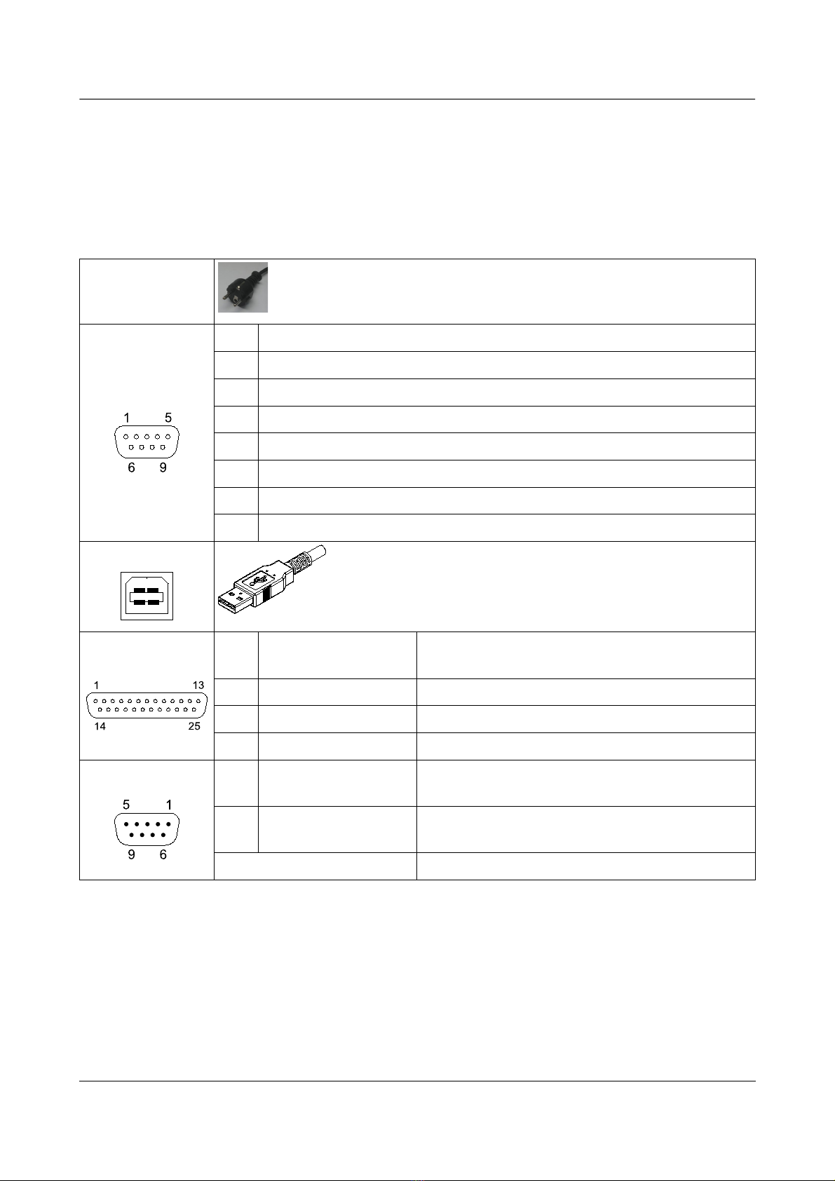
3 onnection Diagram
Power 8 – 264 VAC, 0.4 A, 0/60 Hz
Note: Always use Earthed/Grounded Mains socket.
Load Cell
Pin Value
1 - Signal
2 + Signal
3 - Sense (Note: If load cell is 4-wire connect -Excitation here)
4 + Sense (Note: If load cell is 4-wire connect +Excitation here)
Ground - Shield
6 + Excitation
7 - Excitation
USB
RS-232 Pin Signal PC Connection
(Type-D 9-Pin Male)
2 Tx 2 (Rx)
3 Rx 3 (Tx)
7 Gnd (Gnd)
Remote Display Pin Signal ERTE HG 7 Remote Display Connection
(Type-D 9-Pin Female)
1, 2,
3NC No connection
4, , 6, 7, 8, 9 4, , 6, 7, 8, 9 one-to-one
v1.00 Page 7
USER MANUAL

B2 WEIGHING INDICATOR
4 onfiguration
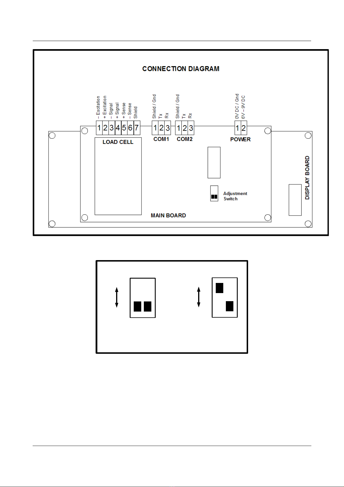
4.1 Adjustment ( alibration) switch
A toggle switch located on main pcb determines the mode of configuration. f the switch is in “LOCKED”
position, it is not possible to alter weighing related settings. f the switch is in “UNLOCKED” position, it
is possible to edit weighing parameters and adjustment data.
v1.00 Page 8
USER MANUAL
Main board Display board
Keypad board
Connectors
INTERNAL VIEW
B2 WEIGHING INDICATOR
v1.00 Page 9
USER MANUAL
ON
OFF
ADJUSTMENT SWIT H
1 2
ON
OFF 1 2
n this position, adjustment
is OFF / LOCKED
n this position, adjustment
is ON / UNLOCKED
Note: Position of switch #2 has no effect
B2 WEIGHING INDICATOR
4.2 onfiguration menu
The position of the adjustment switch determines the method of entering the configuration menu and its
contents. f the adjustment switch is in “UNLOCKED” position, press key to enter configuration
menu. Contents of the menu:
pAR Weighing parameters
AyAr Adjustment ( Calibration )
tFon Miscellaneous Application Settings
Ser RS232 Serial Port Settings
Ser2 Usb Settings
Fab_aY Reset All Settings
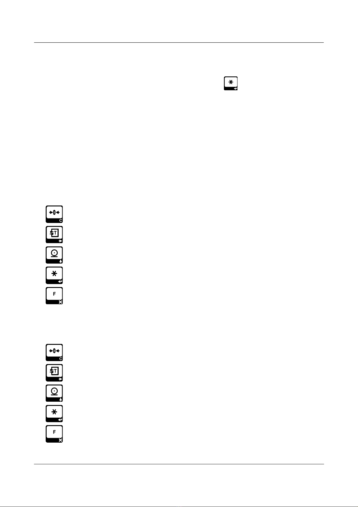
The function of the keys inside the menu are:
Exit: Return to the weighing display.
Previous: Display the previous entry.
Nest: Display the next entry.
Enter: Enter the displayed sub-menu.
ancel: Return to a higher menu level.
When user input is needed while changing a device setting, you are prompted to edit a numerical value.
For this purpose, a numerical value is displayed with a flashing digit. During the edit procedure the
function of the keys are:
lear: The whole value is reset to zero.
Next digit: The flashing moves to the next digit at right. f the rightmost digit is flashing,
the flashing moves to the leftmost digit.
Increment digit value: ncrements the value of the flashing digit by one. f the digit has
a value of 9 the value becomes 0.
Accept: Finish edit procedure by accepting the new value. f the new value is not
acceptable (e.g. out of limits) the edit procedure re-starts with the last value.
ancel: Cancel current edit procedure, return to previous parameter editing (if any).
v1.00 Page 10
USER MANUAL
Table of contents


