KITA KFP01A Series User manual

INSTRUCTION MANUAL
DIGITAL FLOW AND PRESSURE SENSOR
@2022 KITA Sensor Tech. Co., LTD. URL http://www.kita.com.tw
KFP01A Series

KFP01A Series Instruction Manual
@2022 KITA Sensor Tech. Co., LTD. URL http://www.kita.com.tw
-1-
Product Safety InstructionsProduct Safety Instructions
■This section indicate the levels of risks with the labels of Danger, Warning and Caution.
Danger Danger indicates high level of risk, will lead to fatal or serious injuries if
not avoided.
Warning Warning indicates medium level of risk, it might cause death or serious injuries.
Caution Caution indicates low level of risk, it might result in minor injuries, such as scald,
electric shock, etc. and the product, equipment and machines might be damaged.
Warning
■ Working fluid and working environmentWorking fluid and working environment■ Precautions for usePrecautions for use
➀Operate within the specified voltage.Operate within the specified voltage.
Malfunction or damaged product, electric shock or fire may
be resulted by exceeding the specified voltage range.
➁Do not exceed the maximum load current.Do not exceed the maximum load current.
It may damage the product.
➂Do not use any load that generates surges.Do not use any load that generates surges.
Surge protection is present but applying surge voltage
repeatedly will ultimately damage the product.
When using with inductive load (such as relay or solenoid),
please install a flyback diode across the load (polarity must
be observed).
➃Observed the internal voltage drop.Observed the internal voltage drop.
When used at a specified voltage, if the sensor is functional
but the load does not work, please check if the operating
voltage of the load meets the following formula.
➄Please follow the rated range of flow and pressure toPlease follow the rated range of flow and pressure to
avoid damage.avoid damage.
➅Do not use flammable fluids and/or permeable fluids.Do not use flammable fluids and/or permeable fluids.
They may cause fire, explosion or corrosion.
Power supply –
voltage
Internal voltage >
drop of sensor
Minimum operating
voltage of load
Do not use in an explosive gas atmosphere.Do not use in an explosive gas atmosphere.
The sensor does not have explosion-proof structure, fire,
explosion or corrosion can result.
Do not use near a surge voltage generated area.Do not use near a surge voltage generated area.
If product is nearby the device of surge voltage (e.g.,
lightning strikes, solenoid lifters, high frequency induction
furnaces, motors, etc.), please take measures against the
surge sources to prevent damage.
Do not use in an environment where sensors could beDo not use in an environment where sensors could be
splashed by water or oil.splashed by water or oil.
Enclosure rating is IP40, please avoid water or oil splashed
environment to prevent adversely effects.
Do not use in an environment subject to largeDo not use in an environment subject to large
temperature cycling.temperature cycling.
Internal components of the sensor will be damaged by
large heating/cooling cycles other than ordinary changes in
temperature.
Do not mount the product in locations where it isDo not mount the product in locations where it is
exposed to radiant heat.exposed to radiant heat.
➁
➂
➃
➄
➀

KFP01A Series Instruction Manual
@2022 KITA Sensor Tech. Co., LTD. URL http://www.kita.com.tw
-2-
Warning
Caution
■ Wiring PrecautionsWiring Precautions
■ Installation PrecautionsInstallation Precautions
■ Maintenance PrecautionsMaintenance Precautions
■ DisposalDisposal
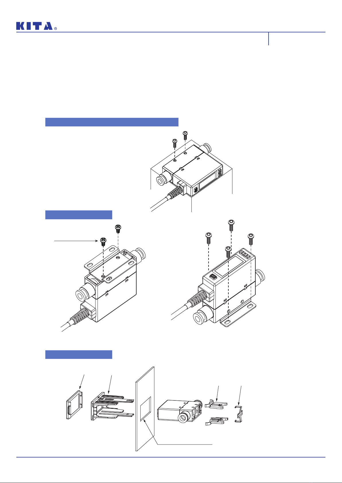
Please follow the specified tightening torque.Please follow the specified tightening torque.
Do not mount the sensor in a place that will be usedDo not mount the sensor in a place that will be used
as a foothold.as a foothold.
The product may damage if sit or step on it accidentally.
When mounting without a bracket, please use P typeWhen mounting without a bracket, please use P type
self-tapping screw- M3 x L 6mm.self-tapping screw- M3 x L 6mm.
Do not remove the fixed pin for the One-Touch Fitting.Do not remove the fixed pin for the One-Touch Fitting.
To avoid losing the internal parts and cause malfunction.
Please do not replace fittings by yourself.Please do not replace fittings by yourself.
While installing the KFP01A-101/201 to the pipe,While installing the KFP01A-101/201 to the pipe,
please apply air tube with I.D. 5 mm.While installingplease apply air tube with I.D. 5 mm.While installing
the KFP01A-005/010/050/100/500 to the pipe, pleasethe KFP01A-005/010/050/100/500 to the pipe, please
applyapply air tube with I.D. 4 mm.air tube with I.D. 4 mm.
The accuracy could change by 2 to 3% when theThe accuracy could change by 2 to 3% when the
piping is removed or replaced.piping is removed or replaced.
Do not touch the terminals or connectors when powerDo not touch the terminals or connectors when power
is on.is on.
Sensors at end-of-life must be disposed of inSensors at end-of-life must be disposed of in
accordance with E-Waste regulations of the country/accordance with E-Waste regulations of the country/
region, NOT disposed of with regular garbage.region, NOT disposed of with regular garbage.
➀
➁
➂
➀
➃
➄
➅
➁
➀
■ Other PrecautionsOther Precautions
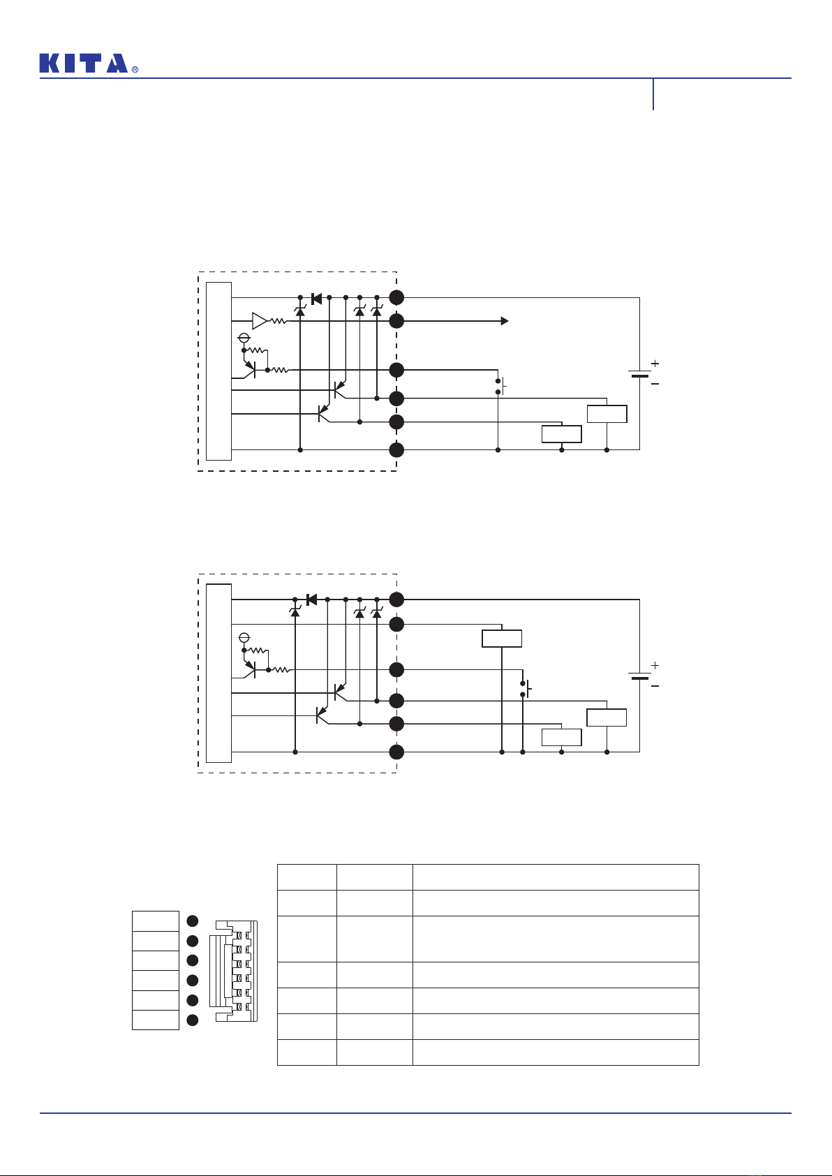
Check wire color and terminal number when wiring.Check wire color and terminal number when wiring.
Incorrect wiring can cause permanent damages to the
sensor, check wire color and terminal number according to
the manual before wiring.
Avoid repeatedly bending or stretching the lead wire.Avoid repeatedly bending or stretching the lead wire.
It can cause damage to the sheath, or breakage of the wire.
Confirm wiring insulationConfirm wiring insulation
Please avoid poor insulations (and interference from another
circuit, poor insulation between terminals, etc.) it can lead to
over current being applied to the product, causing damage.
Please use a separate route for the product wiringPlease use a separate route for the product wiring
and any power or high voltage wiring to avoid noiseand any power or high voltage wiring to avoid noise
interruption.interruption.
Do not short-circuit the load.Do not short-circuit the load.
When the load is short-circuited, an error will be displayed.
But excess current may cause damage to the sensor.
Do not connect wire when the power is on.Do not connect wire when the power is on.
RS485 products must be connected theRS485 products must be connected the
communication wire first.communication wire first.
Wiring for RS485 MODBUS : Please connect RS485 (B+) or
(A-) before connecting power supply to avoid short circuit to
damage to product.
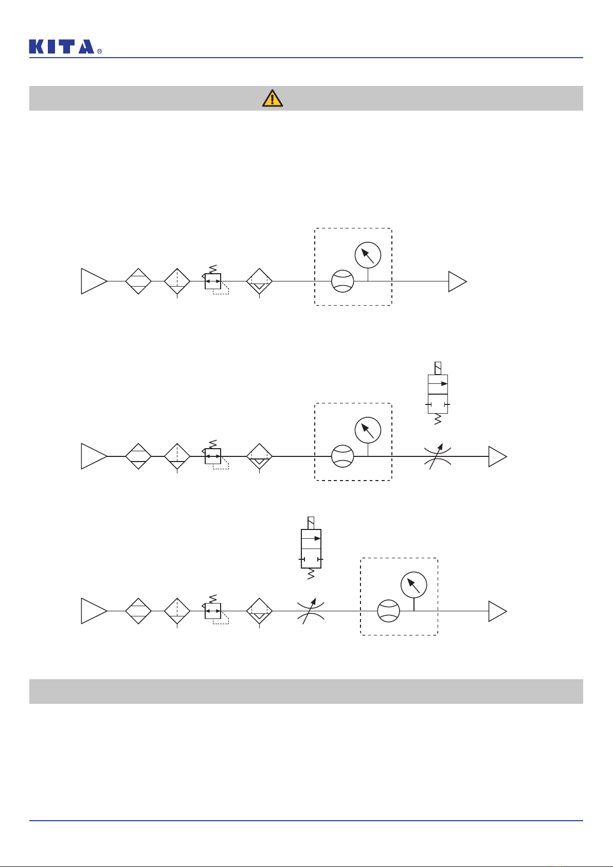
Ensure the flow direction of the fluid.Ensure the flow direction of the fluid.
Install the pipe by following the arrow indication that shows
the air flow direction on the product.
Flush out all dirt and dust by air blow before connectingFlush out all dirt and dust by air blow before connecting
the piping to the sensorthe piping to the sensor..
Do not drop or hit.Do not drop or hit.
When installation, do not drop, hit or apply excessive shock
(100m/s2), permanent damage to the internal component of
the sensor may occur.
Do not install multiple products in close proximity.Do not install multiple products in close proximity.
The heat generated from each product could cause the
temperature to rise and change the characteristics of product
or deterioration of the plastic parts. Please set the products
10mm apart from each other.
Hold the sensor body when installing.Hold the sensor body when installing.
The tensile strength of the cable is 24.5 N and apply
excessive pulling force can cause damage to the sensor.
After power is supplied, the output will remain off untilAfter power is supplied, the output will remain off until
the display is turned on. Please operate the sensorthe display is turned on. Please operate the sensor
after the value is shown.after the value is shown.
Stop the control systems before perform settingStop the control systems before perform setting
changes.changes.
During the initial flow and pressure setting, the product will
switch the output according to the existing settings until the
changes are complete.
➁
➂
➃
➄
➅
➀
➆
➁
➂
➃
➄
➀
➁
➀

KFP01A Series Instruction Manual
@2022 KITA Sensor Tech. Co., LTD. URL http://www.kita.com.tw
-3-
Disclaimer
➀
➂
➁
Our warranty applies solely to our product, not to any other damages and injuries which occur by earthquakes, fires,Our warranty applies solely to our product, not to any other damages and injuries which occur by earthquakes, fires,
the acts by third party, other matters, acts intentionally, acts accidentally, misuse, or other abnormal conditions thatthe acts by third party, other matters, acts intentionally, acts accidentally, misuse, or other abnormal conditions that
are not the responsibility of KITA.are not the responsibility of KITA.
Our warranty applies solely to our product, not to any other additional damages (the loses of business profits,Our warranty applies solely to our product, not to any other additional damages (the loses of business profits,
business interruption, etc.) incurred due to using or misusing the product.business interruption, etc.) incurred due to using or misusing the product.
Our warranty excludes any injuries and damages that happened by using the product beyond the specified range ofOur warranty excludes any injuries and damages that happened by using the product beyond the specified range of
function stated in the catalog or the instruction manual.function stated in the catalog or the instruction manual.
Warning
■ FluidFluid
Recommended Equipments and Installation ExampleRecommended Equipments and Installation Example
※NOTENOTE ※
When measuring the pressure of the inlet side, install a throttle valve or solenoid valve on the outlet side.
When measuring the pressure of the outlet side, install a throttle valve or solenoid valve on the inlet side.
Inlet Outlet
Flow Sensor
Pressure Sensor
KFP01A Series
Air Source Air Dryer Filter Regulator Micro Mist Separator
(Oil Mist Filiter)
※NOTENOTE : When measuring the pressure of the outlet side, install a throttle valve or solenoid valve on the inlet side.
※NOTENOTE : When measuring the pressure of the inlet side, install a throttle valve or solenoid valve on the outlet side.
Inlet Outlet
Flow Sensor
Pressure Sensor
KFP01A Series
Or
Air Source Air Dryer Filter Regulator Throttle ValveMicro Mist Separator
(Oil Mist Filiter)
Inlet Outlet
Or
Flow Sensor
Pressure Sensor
KFP01A Series
Air Source Air Dryer Filter Regulator Throttle
Valve
Micro Mist Separator
(Oil Mist Filiter)
Check the regulator and flow adjustment valve before introducing the fluid.Check the regulator and flow adjustment valve before introducing the fluid.
On the inlet side, be sure to install an air filter below the filtration level of 10um.On the inlet side, be sure to install an air filter below the filtration level of 10um.
The sensing element cannot measure properly if foreign matter adheres to it.
Recommended Equipments and InstallationRecommended Equipments and Installation
➁
➂
➃
➀

KFP01A Series Instruction Manual
@2022 KITA Sensor Tech. Co., LTD. URL http://www.kita.com.tw
-4-
Contents
Installation Instructions 5
1.1 Piping ........................................................................................................ 5
1.1.1 Piping for the One-Touch Fitting ................................................... 5
1.1.2 Piping for the internal thread ......................................................... 6
1.2 Mounting bracket .................................................................................... 7
1.3 Wiring ........................................................................................................ 8
1.3.1 NPN output, Analog output and external input ............................ 8
1.3.2 PNP output, Analog output and external input ............................ 9
1.3.3 NPN output, RS-485 Modbus ..................................................... 10
1.3.4 PNP output, RS-485 Modbus ...................................................... 10
How to Use 11
2.1 Names and Functions of Individual Parts ...................................... 11
2.2 Functions Instructions ........................................................................ 12
2.3 Operation Setting ................................................................................. 14
Modbus RTU Instruction 51
Error Code Instruction 53
Specifications 54
Pressure Loss Characteristics 55
Thermal Mass Principles of Flow Sensor
56
Ordering Information 56
Dimensions 57
Internal Structure 59
1
2
3
4
5
6
7
8
9
10

KFP01A Series Instruction Manual
@2022 KITA Sensor Tech. Co., LTD. URL http://www.kita.com.tw
-5-
Install the pipe by following the
arrow indication that shows the
air flow direction on the product.
Use straight piping 8cm or longer to
connect the Piping Port (Inlet side).
If straight piping is not installed, the
accuracy may vary by ± 2% F.S..
※ Straight Piping: The pipe is without
bending and the cross sectional areas of
the pipe keeps the same.
While installing the
KFP01A-101/201 to the pipe,
please apply air tube with I.D. 5 mm.
While installing the
KFP01A-005/010/050/100/500 to
the pipe, please apply air tube with
I.D. 4 mm.
※ The accuracy can vary by approximately
±2% F.S. when such tubing is not used.
Blow the air to flush out the foreign
matters, dust and etc. before installing
the pipe.
Uncleaned air may cause malfunction or
damage to the product.
Piping for the One-Touch Fitting, insert
the tube firmly into the fitting and make
sure it cannot be pulled out.
Also using the proper tube cutter is
recommended to ensure square edge
tube.
※ Recommends using PU tube.
Installation
1InstallationInstallation
1.1 Piping
1.1.1 Piping for the One-Touch Fitting
Flow
direction
Piping Port
(Inlet side)
straight piping 8cm
or longer
Piping Port
(Outlet side)

KFP01A Series Instruction Manual
@2022 KITA Sensor Tech. Co., LTD. URL http://www.kita.com.tw
-6-
Install the pipe by following the
arrow indication that shows the
air flow direction on the product.
Use straight piping 8cm or longer to
connect the Piping Port (Inlet side).
If straight piping is not installed, the
accuracy may vary by ± 2% F.S..
※ Straight Piping: The pipe is without
bending and the cross sectional areas of
the pipe keeps the same.
While installing the
KFP01A-101/201 to the pipe,
please apply air tube with I.D. 5 mm.
While installing the
KFP01A-005/010/050/100/500 to
the pipe, please apply air tube with
I.D. 4 mm.
※ The accuracy can vary by approximately
±2% F.S. when such tubing is not used.
When mounting the fitting, a wrench should be used
on the metal part.
Using on other parts of the product with a wrench may
damage the product.
If the tightening torque is exceeded, the product can
be broken.
If the tightening torque is insufficient, the fitting may
become loose and cause air leakage.
After installation completed, turn on the gas and
power supply for proper operation and leaking test to
confirm whether the installation is correct.
Installation
1.1.2 Piping for the internal thread
Flow
direction
Piping Port
(Inlet side)
straight piping 8cm
or longer
Piping Port
(Outlet side)
Caution

KFP01A Series Instruction Manual
@2022 KITA Sensor Tech. Co., LTD. URL http://www.kita.com.tw
-7-
1.2 Mounting Bracket / Optional Parts
The LCD display may be difficult to see at certain angles.
The sensor can be installed horizontally or vertically, but the flow rates may
change because of the installation way of the product or piping.
The tightening torque for screws should be under 0.5 ±0.1 N.m.
Installation
1 . Horizontal mounting
(by Through-Hole)
Mounting screw
P Type
Size : 3.0
Length : 6mm
※ The tightening torque for bracket mounting
screws should be under 0.5 ± 0.1 N.m.
Mounting
screw
Mounting screw
Front protective lid Panel adapter
Panel adapter
60.5 x 22.5 ±0.3mm
Panel adapter
2 . Bracket mounting
3 . Panel mounting

KFP01A Series Instruction Manual
@2022 KITA Sensor Tech. Co., LTD. URL http://www.kita.com.tw
-8-
1.3 Wiring Diagrams
1.3.1 NPN Output, Analog Output and External Input
Installation
● NPN Output / Analog Voltage Output / External Input
● NPN Output / Analog Current Output / External Input
Main CircuitMain Circuit
1
2
3
4
5
6
Brown (Power supply +)
Blue (Power supply –)
Black (Output 1)
Black (Output 1)
White (Output 2)
White (Output 2)
Yellow (External input)
Yellow
(External input)
1kΩOrange
(Analog output)
Orange
(Analog output)
1
2
3
4
5
6
Load
Load
Load
Load
Load
Brown
Orange
Yellow
Black
White
Blue
Pin No. Line color Content
1 Brown Power supply (DC 12 to 24V DC)
4 Black Output 1 (Max. load current:125mA)
5 White Output 2 (Max. load current:125mA)
3 Yellow External input
2 Orange Analog voltage output:1 ~ 5V
Analog current output:4 ~ 20mA
6 Blue 0V (GND)
1
2
3
4
5
6

KFP01A Series Instruction Manual
@2022 KITA Sensor Tech. Co., LTD. URL http://www.kita.com.tw
-9-
1.3.2 PNP Output, Analog Output and External Input
Installation
● PNP Output / Analog Voltage Output / External Input
● PNP Output / Analog Current Output / External Input
1
2
3
4
5
6
Brown (Power supply +)
Blue (Power supply –)
Black (Output 1)
White (Output 2)
Black (Output 1)
White (Output 2)
Yellow (External input)
Yellow
(External input)
Orange
(Analog output)
Orange
(Analog output)
1
2
3
4
5
6
1kΩ
Main CircuitMain Circuit
Load
Load
Load
Load
Load
Brown
Orange
Yellow
Black
White
Blue
Pin No. Line color Content
1 Brown Power supply (DC 12 to 24V DC)
4 Black Output 1 (Max. load current:125mA)
5 White Output 2 (Max. load current:125mA)
3 Yellow External input
2 Orange Analog voltage output:1 ~ 5V
Analog current output:4 ~ 20mA
6 Blue 0V (GND)
1
2
3
4
5
6

KFP01A Series Instruction Manual
@2022 KITA Sensor Tech. Co., LTD. URL http://www.kita.com.tw
-10 -
1.3.3 NPN Output, RS-485 Modbus
1.3.4 PNP Output, RS-485 Modbus
Main Circuit
Brown (Power supply +)
Blue (Power supply –)
Black (Output 1)
White (Output 2)
Yellow
RS-485 (A-)
Orange
RS-485 (B+)
1
2
3
4
5
6
Load
Load
1
2
3
4
5
6
Brown (Power supply +)
Blue (Power supply –)
Black (Output 1)
White (Output 2)
Yellow
RS-485 (A-)
Orange
RS-485 (B+)
Main Circuit
Load
Load
Brown
Orange
Yellow
Black
White
Blue
Pin No. Line color Content
1 Brown Power supply (DC 12 to 24V DC)
4 Black Output 1 (Max. load current:125mA)
5 White Output 2 (Max. load current:125mA)
3 Yellow RS-485 (A-)
2 Orange RS-485 (B+)
6 Blue 0V (GND)
1
2
3
4
5
6
Installation

KFP01A Series Instruction Manual
@2022 KITA Sensor Tech. Co., LTD. URL http://www.kita.com.tw
-11-
2How to UseHow to Use
2.1 Names and Functions of Individual Parts
How to Use
Setting Button
Use for selection each mode
and set value confirmation.
▼Button
▲Button
Use for mode selection,
ON/OFF switching and
set value adjustment.
Use for mode selection,
ON/OFF switching and
set value adjustment.
Lead Wire
Connector
Piping Port (Inlet side)
Piping Port (Outlet side)
LCD Display
Through-Hole
Use to mount the product
on a plate directly.
Body
Connector
Output 1 Indicator
3 Color LCD Display Flow Symbol
Flow Display
Button
Button
Analog Signal Indicator
Output 2 Indicator
Output 1 Indicator
Output 2 Indicator
Analog Signal Indicator
Pressure Symbol
Pressure Display
Setting Button
Pressure Unit
Display Section
Flow Unit
Display Section
Ag OUT1OUT2 Ag OUT1OUT2
kgf/cm2bar psi kPa Pulse ft3/min mL3/min

KFP01A Series Instruction Manual
@2022 KITA Sensor Tech. Co., LTD. URL http://www.kita.com.tw
-12-
● Function Setting Mode
Function
Code Item Default setting Explanation Page
[F-01]
[oUt1] OUT1 setting
Select Output 1 corresponding
to flow sensor or pressure
sensor.
Set the flow rate or pressure
value to switch ON/OFF.
P.15
[oUt1] OUT1 sensor correspondence FLo
[FLo ] OUT1 output mode HYS
[oUt1] OUT1 output type no
[Fl-1] OUT1 set value input
50% of maximum measured flow rate
005 : 250 mL/min, 010 : 500 mL/min
050 : 2.50 L/min, 100 : 5.00 L/min
500 : 25.0 L/min, 101 : 50.0 L/min
201 : 100 L/min
[FH-1] OUT1 set value input
60% of maximum measured flow rate
005 : 300 mL/min, 010 : 600 mL/min
050 : 3.00 L/min, 100 : 6.00 L/min
500 : 30.0 L/min, 101 : 60.0 L/min
201 : 120 L/min
[F-02]
[oUt2] OUT2 setting
Select Output 2 corresponding
to flow sensor or pressure
sensor.
Set the flow rate or pressure
value to switch ON/OFF.
P.20
[oUt2] OUT2 sensor correspondence FLo
[FLo ] OUT2 output mode HYS
[oUt2] OUT2 output type no
[Fl-2] OUT2 set value input
50% of maximum measured flow rate
005 : 250 mL/min, 010 : 500 mL/min
050 : 2.50 L/min, 100 : 5.00 L/min
500 : 25.0 L/min, 101 : 50.0 L/min
201 : 100 L/min
[FH-2] OUT2 set value input
60% of maximum measured flow rate
005 : 300 mL/min, 010 : 600 mL/min
050 : 3.00 L/min, 100 : 6.00 L/min
500 : 30.0 L/min, 101 : 60.0 L/min
201 : 120 L/min
[F-03]
[CLor] LCD Display setting
Select back light color and
display mode. P.21
[disp] LCD Display corresponding
to output oUt1
[ CoL] LCD Display color setting SoG
[F-04]
[rESP] Flow/Pressure sensor
setting FLo Select the response time for
switch output.
Pressure sensor: 2.5ms ~ 1500ms
Flow sensor: 50ms ~ 1500ms
P.22
[FLo ] Response time setting 800(ms)
[F-05]
[UPdA] Flow/Pressure sensor
setting FLo Display refresh cycle can be
set in 200ms, 500ms or 1000ms. P.24
[UPdA] Display refresh time of flow
sensor setting 500(ms)
[F-06]
[Unit] Unit setting
Select the UNIT of pressure /
flow sensor. P.26
[FLo ] Flow unit setting LPn
[PrES] Pressure unit setting PA
[F-07][rEFE] Flow reference standard
setting Anr
Select the flow value is shown
under standard (ANR) or normal
condition (NOR).
P.27
How to Use
2.2 Function Instruction

KFP01A Series Instruction Manual
@2022 KITA Sensor Tech. Co., LTD. URL http://www.kita.com.tw
-13-
● Measurement Mode
Function
Code Item Default setting Explanation Page
[F-08] [AnG] Analog output setting FLo Select the analog corresponding to
pressure or flow sensor. P.28
[F-09][EEPr] Accumulated value hold setting oFF To save the last accumulated flow
value every 2 or 5 minutes. P.29
[F-10] [diS]
Flow sensor display mode setting
Select to display Instantaneous Flow
or Accumulated Flow Mode.P.30
[ dsP]
Flow sensor display mode setting
inS
[F-11][FLUi] Fluid setting Air Select desired fluid. P.31
[F-80][ SYn]Sync the value of flow analog
output and display oFF Turn ON to synchronize the value of
flow analog output and display. P.32
[F-90]
[AoUt] Analog output range setting oFF
Adjust the desired flow or pressure
range corresponding to analog output. P.33
[AG L] Min. value of desired flow or
pressure range 0
[AG H] Max. value of desired flow or
pressure range
Pressure sensor :
1000 kPa
Flow sensor : Max.
measured flow rate
[F-91][ Eco] Power-Save mode setting no Select if turn on power-save mode to
reduce power consumption P.37
[F-92] [inP] External input setting r r Select for Accumulated flow rate zero
clear, Auto-Shift or Auto-Shift zero. P.38
[F-93]
[nbUS] Modbus RTU setting
Set ID number, baud rate and
transmission format. P.39
[ id] ID number setting 1
[ rAT] Baud rate setting 96(9600 Bd)
[ For] Transmission format setting n81
[ trA] Communications protocol setting rTU
[F-94][FinE] Fine adjustment setting oFF The displayed value can be adjusted
slightly. P.41
[F-95]
[FoUt] Forced output function
To force output ON/OFF to test the
switch function. P.43
[oUT1] Forced output function oFF
[oUT2] Forced output function oFF
[F-99] [rEsT] Reset to the default setting Return to the factory default setting. P.44
[ rsT] Reset to the default setting oFF
Item Explanation
Flow display Display instantaneous flow rate.
Accumulated flow rate display Display accumulated flow rate.
Instantaneous Flow rate zero setting
The displayed instantaneous flow rate value can be adjusted to "0".
Accumulated flow rate zero clear The accumulated flow rate can be set to "0".
Peak value display
The maximum pressure or instantaneous flow can be detected when the power is supplied for a period.
Bottom value display
The minimum pressure or instantaneous flow can be detected when the power is supplied for a period.
Key lock/unlock mode To prevent errors occurring due to unintentional changes of the set values.
How to Use

KFP01A Series Instruction Manual
@2022 KITA Sensor Tech. Co., LTD. URL http://www.kita.com.tw
-14-
Function Selection Mode
At Measurement Mode, press button for more than 3 sec. to display
[F-01]. Press or button to select other setting functions.
Press for 3 sec. at Function Setting Mode to return to Measurement
Mode.
2.3 Operation Instructions
How to Use
Measurement Mode
Press button for
more than 3 sec.
Press button
Function Selection Mode
Enter in each function setting
kPa /minL
Ag
kPa /minL
Ag
kPa kPa/min /minL L
Ag Ag

KFP01A Series Instruction Manual
@2022 KITA Sensor Tech. Co., LTD. URL http://www.kita.com.tw
-15-
Press button (to be continued)
Setting corresponding sensor and operating mode of OUT1.
● 1. Flow sensor setting1. Flow sensor setting
Press or button at Function Selection Mode to display [F-01] [oUt1].
How to Use
2.3.1 [F-01] OUT1 Setting
Press button
Press button
Output Mode Setting
Select output mode :Select output mode :
Press or button to select output
mode of OUT1.
4 output modes included.
Hysteresis Mode
※ NOTE : Accumulated Pulse Mode is available in OUT1, but not in OUT 2.
Window Comparator Mode Accumulated Output Mode Accumulated Pulse
Output Mode
Sensor Selection
Selected
Output
Set Value
Press or button to select flow
sensor of OUT1.
Flow sensor Pressure sensor
kPa /minL
Ag
kPa kPa/min /minL L
Ag Ag
Selected
Sensor
Set Value
kPa /minL
Ag
kPa /minL
Ag
kPa /minL
Ag
kPa /minL
Ag
kPa /minL
Ag

KFP01A Series Instruction Manual
@2022 KITA Sensor Tech. Co., LTD. URL http://www.kita.com.tw
-16-
How to Use
Press button
Press button
Press button to return to
Function Selection Mode
Set Value Setting
Fixed Hysteresis Setting
OUT1 set value setting :OUT1 set value setting :
Fixed hysteresis setting :Fixed hysteresis setting :
Press or button to adjust the set
value.
Press or button to adjust fixed
hysteresis value.
Hysteresis Mode [HYS] : [FL-1],[FH-1]
Window Comparator Mode : [FL-1],[FH-1]
Accumlated Output Mode [ADD] : [AdL1],[AdH1]
※ NOTE : Set value setting will not display when Accumulated Pulse
Output is set.
※ NOTE : Fixed hysteresis setting is available when selecting Window Comparator Mode.
Output Type Setting
Selected
Output
Set Value
Press or button to select OUT1
type.
NO mode NC mode
kPa /minL
Ag
kPa /minL
Ag
OUT1 type setting :OUT1 type setting :
kPa /minL
Ag
Selected
Mode
Selected
Mode
Set Value
Set Value
kPa
kPa
/min
/min
L
L
Ag
Ag
Fixed Hysteresis
Mode
Set Value
kPa /minL
Ag
※ NOTE : Type setting will not display when Accumulated Pulse Output Mode is set.
kPa /minL
Ag

KFP01A Series Instruction Manual
@2022 KITA Sensor Tech. Co., LTD. URL http://www.kita.com.tw
-17-
How to Use
Press button (to be continued)
● 2. Pressure sensor setting2. Pressure sensor setting
Press or button at Function Selection Mode to display [F-01] [oUt1].
Press button
Press button
Output Mode Setting
Select output mode :Select output mode :
Press or button to select output
mode of OUT1.
Hysteresis Mode Window Comparator Mode One Point Set Mode
Sensor Selection
Selected
Output
Set Value
Press or button to select
pressure sensor of OUT1.
Flow sensor Pressure sensor
kPa /minL
Ag
kPa kPa/min /minL L
Ag Ag
Set Value Sensor
kPa /minL
Ag
kPa /minL
Ag
kPa /minL
Ag
kPa /minL
Ag

KFP01A Series Instruction Manual
@2022 KITA Sensor Tech. Co., LTD. URL http://www.kita.com.tw
-18-
How to Use
Press button
Press button
Press button to return to
Function Selection Mode
Set Value Setting
Fixed Hysteresis Setting
OUT1 set value setting :OUT1 set value setting :
Fixed hysteresis setting :Fixed hysteresis setting :
Press or button to adjust the set
value.
Press or button to adjust fixed
hysteresis value.
Hysteresis Mode [HYS] : [L-1],[H-1]
Window Comparator Mode : [L-1],[H-1]
One Point Set Mode [oPS] : [P-1]
※ NOTE : Fixed hysteresis setting will not display when Hysteresis Mode is set.
Output Type Setting
Set Value Output
Press or button to select OUT1
type.
NO mode NC mode
kPa /minL
Ag
kPa /minL
Ag
OUT1 type setting :OUT1 type setting :
kPa /minL
Ag
Set Value
Set Value
Mode
Mode
kPa
kPa
/min
/min
L
L
Ag
Ag
Fixed Hysteresis
Mode
Set Value
kPa /minL
Ag
kPa /minL
Ag

KFP01A Series Instruction Manual
@2022 KITA Sensor Tech. Co., LTD. URL http://www.kita.com.tw
-19-
How to Use
OFF
ON
Flow / Pressure
Hysteresis Mode
Hysteresis Mode
FL-1
(FL-2)
L-1(L-2)
FH-1
(FH-2)
H-1(H-2)
OFF
ON
0 L
Time
AdH1
AdL1
AdH2
AdL2
Normal Open Mode
Normal Close Mode
OFF
ON
P-1
(P-2)
Time
Pressure
Flow
Window Comparator Mode
One Point Set Mode
Accumulated Output Mode
Accumulated Pulse Output Mode
Flow / Pressure
Accumulated Output Mode
Flow
One Point Set Mode
Pressure
Window Comparator Mode
Flow / Pressure
Flow / Pressure
OFF
ON
FL-1
(FL-2)
L-1(L-2)
FH-1
(FH-2)
H-1(H-2)
FL-1
(FL-2)
L-1(L-2)
FH-1
(FH-2)
H-1(H-2)
OFF
ON
FL-1
(FL-2)
L-1(L-2)
FH-1
(FH-2)
H-1(H-2)
OFF
ON
OFF
ON
P-1
(P-2)
OFF
ON
0 L
AdH1
AdL1
AdH2
AdL2
【NOTE:】
*1. In case hysteresis is set at less than or equal to 2 digits, switch output may chatter if input detected fluctuates near the set point.
*2. When using window comparator mode, the difference between two set points must be greater than the fixed hysteresis, otherwise
will cause the switch output to malfunction.
OFF
ON
Time
50ms
Flow Range 500mL
5mL
1000mL 5L 10L 50L 100L 200L
10mL 0.05L 0.1L 1L 2L0.5L
Pulse Output Rate
Table of contents
Other KITA Accessories manuals