ESA Tribo-Check TC30 User manual

TC30 EMISSION CONTROL PROBE Tribo-Check® 4÷20 mA
PLEASE READ THE WHOLE USER MANUAL CAREFULLY BEFORE INSTALLING THE EQUIPMENT
DOCUMENTATION CONTENTS
1. General description
2. Installation rules
3. Electrical wiring diagram
4. Technical characteristics
5. Positioning and functioning
6. Calibration
7. CE Certification
1. GENERAL DESCRIPTION
1.1 PREREQUISITE
The need to signal in advance possible leakages of the dedusting system avoiding high costs of environmental reclamation
and of plants stop-overs brought, since a long time, to the use of electronic equipments dedicated to a better
environmental safeguard. With the use of these devices it is possible to signal any failure that can produce dangerous
emissions in the atmosphere which are symptom of breakdown in the dedusting plant. Especially, it is possible to control
any breaks of the filtering surfaces, broken bags or cartridges.
The use of TC probes allows therefore to identify the dust particles which are present in the gases that go through the filter
due to any breaks or failures of the bags or cartridges where the quantities of dusts to remark are considerable 100÷400
mg.
For a correct functioning of the TC probe, the cartridges or the bags must be mounted in a vertical position.
The TC probe is seldom used for the continuous monitoring of the dustiness degree present in the discharge duct of the
gases in the atmosphere.
The above-mentioned use entails a more complicated calibration and a deep knowledge of the device.
1.2 TRIBO-CHECK® TC PROBE OPERATION PRINCIPLE
The probe’s operation principle is founded on the TRIBO ELECTRIC ‘T-E’ effect.
This physical phenomenon is caused by the friction of particles suspended in the air against the surface of a probe which
is placed in the measurement area. Particular electronic circuits which are located inside the probe allow to transform the
static electricity generated by the T-E phenomenon into the electric signal proportional to the quantity of particles that
generated it.
1.3 SENSITIVITY TO THE 'TE' EFFECT
The sensitivity to the TRIBO-ELECTRIC effect of the probe varies according to the type of dusts to be monitored. On the
basis of acquired experiences, it has been established that this sensitivity, namely the possibility that the probe
generates an electric signal consequently to the collision of the particles suspended in the gases to be monitored, starts
with minimum dust concentrations from 3÷8 mg/m3 to 200 mg/m3 in an acceptable linear way.
The signal generated by the TC probe depends on the type of material analyzed, the speed of the gas in the duct, the
probe’s length and the density of the particles in the duct.
1.4 OPERATION
The TC probe notes the passage of particles which are present in the gases by turning this physical phenomenon into an
electric signal 4÷20 mA proportional to the dustiness degree.
A rotary switch located inside the head of the probe (SW 21) allows to change the amplification of the exit signal in order
to permit a correct use of the TC probe in the most part of the dedusting systems.
The output signal (4÷20 mA) can be adjusted to program the activation of any alarms when the dust emissions overtake
the values which have been set according to the law restrictions allowed.
Code: TC30-500
S/N:
Date: 23 / 02 / 2012 ESACODE Ver. 12.0

2. INSTALLATION RULES
2.1 For connections to PLC or to other devices please use the provided units with galvanically isolated entry.
2.2 DO NOT REMOVE the PL connector with power supply ON. TC probe could be damaged in no reparable way.
2.3 For the electrical connections use antiflame shielded cable 3 x 0,75 mm²
2.4 Remove the TC probe in case of electric weldings on the support structure of it and during the maintenance.
2.5 Pretect the 'head' of the probe against the direct exposure to sun light.
2.6 Every kind of operation on TC probe must be done without dust in the air and, when it is possible, with supply voltage Off
2.7 A remarkable quantity of rain or water in the sampled gases could distort the reading of the signal.
3. WIRING DIAGRAM
4. TECHNICAL FEATURES
Supply Voltage 16 ÷ 24 VDC 100 mA
Output signal 4 ÷ 20 mA Activ. Maximum load 350 Ohm
GAS temperature: 120°C with BS40 (Standard)
GAS temperature: 200°C with BS200 (On Request)
GAS temperature: 400°C with BS400 (On Request)
Operating temperature - 10 ÷ + 50 °C
Relative humidity 80 %
Protection degree IP65
Particle Size >= 0.3 µm
We reserve the right to make any change without notice Pg. 2

5. POSITIONING AND OPERATING
5.1 POSITIONING AND OPERATING
The installation of the TC probe is done by fixing the BS40 flange
to the duct to be monitored.
The BS40 flange, in AISI304 material, should be fixed in a part of
the duct where isokinetic conditions happen.
The above condition, as a general rule, is placed at a distance of
6÷10 times from the diameter of the duct from the nearer bend
from the side of the origin of the gases.
In this area, the components of turbulence in the gases present
inside the duct are practically unimportant.
This condition is essential for the correct functioning of the
monitoring and the reliability of the registered data.
It is suitable to install the probe with a slight bent downwards
(head of the probe slightly upward compared to the end of the
metallic pole) so that possible drops of condensation that can
appear on the sensitive part of the probe can slip into the duct.
5.2 HOLE FOR CALIBRATION
For the next calibration for the simulation of the TC probe, it is
necessary to provide for a hole with its plug in order to allow the
introduction of dust. This hole should be positioned in vertical
line duct under the TC probe at a certain distance to assure
isokinetic conditions in the point of measurement (see next
picture A).
5.3 FASTENING
The standard BS40 flange is a muff male thread of 1¼ GAS with 35 mm
hole.
BS40 is fixed to the duct by means of a welding on the same axis where
the 35mm hole has been made. See the picture.
When the fixing operation of the probe is finished, introduce the TC probe.
The probe is fixed by closing the dice of 1¼ GAS.
In case of high temperatures, consider longer flanges (see the picture)
5.4 DUCT GROUNDING
For a correct functioning of the probe it is essential that the sampling duct
is connected to the ground.
5.5 MAINTENANCE
The TC probe does not require a particular maintenance.
Could be necessary polish up with a rag soaked of detergent (alcohol,
gasoline etc.) the sensitive part of the probe (inside pole) without
particular precautions.
The necessity to clean the probe should be checked after any months of
operation, checking that possible deposits have provoked alterations to
the operation of the probe.
Wrench 46 to tighten the 1 ¼ GAS sleeve nut
BS40
1¼ GAS male threaded sleeve welded to the duct BS200 and BS400 available upon request
Pg. 3

6. PROBE CALIBRATION
There are three methods for the calibration of the TC probe
1. For COMPARISON with data coming from isokinetic analysis in the gas to be sampled.
2. For SIMULATION with pre-weighed quantities put in the duct if the datas from the isokinetic analysis done in apposite laboratories are not
available.
3. Calibration to detect only the broken bag or broken cartridge.
6.1 CALIBRATION FOR COMPARISON (SEE PRACTICAL EXAMPLE CALIBRATION FOR COMPARISON 6.6)
In order to proceed with the calibration of the probe, you must know the data concerning the quantity of dust present in the gases in mg/m3.
These data are normally released by special laboratories during the periodical gas analysis These analysis must be done according to the
law restrictions.
6.2 CALIBRATION FOR SIMULATION (SEE PRACTICAL EXAMPLE CALIBRATION FOR SIMULATION 6.7)
The calibration of the probe is recommended after a certain period of operation of the plant. The above mentioned period is necessary to
allow the filtering material to reach the typical characteristics of the functioning (filter partially dirty).
6.3 CALIBRATION OF THE 4÷20 mA SIGNAL
The function of the TC probe is to convert the triboelectric ‘T-E’ physical phenomenon, produced by a certain quantity of dust present in the
gases, in an electric signal ‘STC’ 4÷20 mA.
In order to calibrate the STC signal, it is essential that the sampling duct contains a measurable quantity of dust.
In default of dust, it is impossible to proceed with the calibration.
The STC signal must be calibrated in order to cover the whole range of emissions.
In order to proceed with the calibration, the probe must be connected to an instrument that detects the 4÷20mA output signal.
1. Without dust emissions, the value must be 4mA (value pre-determined by the calibration from the manufacturer’s laboratory).
2. With the maximum value of emissions estimated, the signal must be around 14÷18 mA.
In practice, if according to law regulations for certain types of material the maximum level of emissions allowed is equal to 20 mg/m3, the
STC signal must be adapted to this value in the presence of maximum emissions.
You can get this calibration by acting on the rotary switch present inside the head of the probe (SW21).
By leaving a margin of 20÷30 % against the maximum value allowed, you can consider that: 0÷20 mg/m3 = 4÷17 mA.
Over 20 mA the STC signal saturates by making insignificant the higher values of dustiness.
This fact does not constitute a problem, since the goal of this application is to control by means of an alarm threshold that the emission
limits envisaged by the law are not overtaken.
The STC signal generated is handled by electronic equipments (ESA sequencers, PLC, PC) that convert it into a digital value.
The digital value can easily be adapted to the value of the quantity of dust present in the duct.
6.4 SENSITIVITY
The TC probe, by triboelectric effect generates a STC electric signal which is function of 4 parameters:
1 Length of the probe
2 Speed of the gases in the sampling duct
3 Type of material present in the smokes
4 Density of dust
The degree of sensitivity of the probe means the possibility to convert the value of the T-E signal (source) in a certain STC 4÷20mA electric
signal that can be used by the various equipments connected to it.
The ratio KTC between the two entities is called SENSITIVITY: STC = KTC x T-E.
6.5 SENSITIVITY REGULATION
KTC is a variable coefficient depending by the switch SW21 place inside of the TC probe (See Pg. 2).
SW21 allows to change the sensibility amplifying or attenuating the response of STC.
Normally SW21 comes set in position 4 to a low level after the laboratory tests.
Pg. 4

6. PROBE CALIBRATION
6.6 PRACTICAL EXAMPLE OF CALIBRATION FOR COMPARISON
It is supposed to know, by means of data coming from previous analysis, that the duct contains around 10 mg/m3 with an output signal of
18 mA.
Suppose that the maximum value allowed by the law is of 20 mg/m3.
In order to obtain the best calibration, you should adapt the two values in the way that about 70% of the STC signal (15÷16 mA)
corresponds to the maximum dustiness value allowed (20 mg/m3).
On a scale of 4÷20 mA. The value at 50% is of 12 mA
Having previously noticed an output signal from the probe of 18 mA for 10 mg/m3, it is evident that the amplification is too high.
An increase of 30 % of dustiness can be enough to bring the signal to the full range around 20mA by rendering illegible all the emission
values above 13 mg/m3.
Therefore, it is necessary to reduce the sensitivity through SW21 placed inside the probe.
If you consider a higher margin of reading of 30% of STC over the maximum limit of emissions allowed ( 20mA = 20 mg/m3+ 30% = 26
mg/m3 ), a simple calculation shows that at 10 mg/m3 the signal must be around 10÷11 mA.
Therefore, it is sufficient to regulate the SW21 rotary switch in the way to bring the STC output signal around this range of current and set
the activation of the alarm of high emission at about16 mA.
6.7 PRACTICAL EXAMPLE OF CALIBRATION FOR SIMULATION
If the data obtained by the analysis are not available, by following this most approximate method it is possible to make the same
calibrations as previously described. You must simulate an emission of a certain quantity of dust.
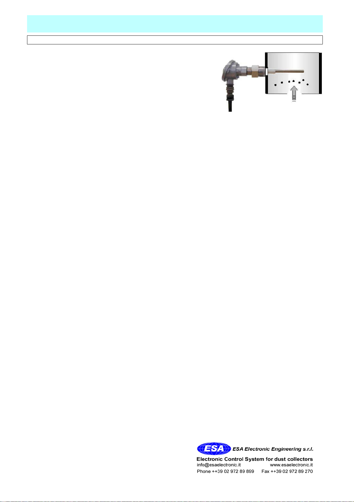
This method consists in putting the pre-weighed quantities through the hole mentioned in point 5.2 into the sampling duct in a pre-fixed
time and measure the STC signal generated by the TC probe.
For this calibration it is necessary to know the range of the duct.
The calibration for simulation cannot be done in the absence of dust.
The following example indicates how to proceed:
Range of the duct = 100000 m3/h
Emission that you wish to simulate = 10 mg/m3
Time of insertion of dust in the duct = 60sec.
Quantity of dust to out in 1 minute = 10x100000x60/3600 = 16,66 g.
So, putting in the duct 16,66g in 1 minute, the correspondent emission is 10 mg/m3
Proceed as indicated in point 6.3 CALIBRATION OF THE 4÷20mA SIGNAL
6.8 CALIBRATION OF THE ALARM FOR BROKEN BAG OR BROKEN CARTRIDGE
This type of calibration is relatively simpler than the previous example 6.6 and 6.7 because it consists in checking that the STC signal
detects an anomalous passage of dust in the duct..
As the broken bag or the broken cartridge causes emissions of considerable quantities of dust which are visible at the exit of the chimney,
the calibration of the probe becomes simpler.
This type of calibration is done by throwing in the duct a handful of dust through the hole (see point 5.2) and checking the increase of the
STC signal which is generally considerable.
This peak of the STC signal is used to detect the broken bag by means of the connected equipments or the internal relay in case of
TR30R probe.
WARRANTY
The warranty lasts 4 years. The company will replace any defective electronic component, exclusively at our
laboratory, unless otherwise agreed, upon the Company's prior consent.
WARRANTY EXCLUSION
The warranty is not valid in case of:
1) Tampering or unauthorized repairs.
2) Wrong use of the device, not in compliance with technical data.
3) Wrong electrical wiring.
4) Inobservance of the installation rules.
5) Use of the device, not in compliance with CE rules.
6) Atmospheric events (Lightning, electrostatic discharge), Overvoltage.
Pg. 5

DICHIARAZIONE DI CONFORMITA' DEL COSTRUTTORE
CONFORMITY DECLARATION OF THE MANUFACTORY
Mesero, 14 marzo, 2006
G. BELLINELLI
Amministratore delegato / Managing director
ESA ELECTRONIC ENGINEERING s.r.l.
Nome del costruttore:
ESA Electronic Engineering
Indirizzo del costruttore:
via J.Kennedy 28 I 20010 Mesero (Mi) Italia
Dichiara che il prodotto:
Nome del Prodotto(i): Controllo Emissioni
Modello: TC30-
Opzioni del prodotto: Tutte
E' conforme alle seguenti direttive:
Direttiva Macchine 2006/42/CE 'compatibilità
elettromagnetica'
rispondenti alle
norme Europee armonizzate
EN61000-6-2:2005 classe B della norma
EN61000-6-4:2001
Direttiva Bassa Tensione (DBT) 2006/95/CE
rispondente alle norme Europee armonizzate
EN 60947-1:2004
Informazioni supplementari:
I prodotti sono stati sottoposti a test in
configurazione tipica e con potenza di carico
2 watt
Manufactory name:
ESA Electronic Engineering
Manufactory address
via J.Kennedy 28 I 20010 Mesero (Mi) Italia
Declare that the device:
Device(s) name: Emission Control
Model: TC30-
Device options: All
Meets the following directive:
Machine Directive 2006/42/CE
'electromagnetic compatibility'
related to the
European Standard
EN61000-6-2:2005 class B of the rule
EN61000-6-4:2001
Low Voltage Directive 2006/95/CE related to the
European Standard EN 60947-1:2004
Additional informations
the devices were tested in typical configuration
with load power of 2 watt
Table of contents
Popular Accessories manuals by other brands

Orava
Orava EB-160A instruction manual

Altinex
Altinex Pop `N Plug PNP300 user guide

Caldwell
Caldwell Shootin' Gallery Assembly and usage instructions

Hubbell
Hubbell LightHawk LHMT Installation and operating instructions

PCB Piezotronics
PCB Piezotronics ICP 105C02 Installation and operating manual

Bühler technologies
Bühler technologies TC MINI Installation and operation instructions