Escorts FarmTrac 45 DT User manual
OPERATOR ’S
M A N U A L
OPERATOR ’S
M A N U A L
45 DT

2
CONTENTS
Page
LimitedWarranty ii
FederalEmission Warranty iii-iv
Introduction v
Safety Precautions vi-viii
UniversalSymbols ix
RoadSpeed Decal ix
Safety Decals x
CONTROLS,INSTRUMENTS AND OPERATION
Operator’s Seat, Seat Belt, Safety Frame or Roll Bar 2
Instrumentsand Controls 2
Starting the Engine 4
StoppingtheEngine 5
ParkingBrake 5
FootControls 6
Transmission 7
Power-Take-Off 7
Hydraulic System 9
ThreePoint Linkage 14
TrackAdjustment 17
TractorWeighing 20
Tire Inflation 22
LUBRICATIONANDMAINTENANCE
Lubricationand Maintenance Chart B/2
RoutineServicing B/4
GeneralMaintenance B/21
SPECIFICATIONS
INDEX
SECTION A
SECTION B
SECTION C
SECTION D

LIMITED WARRANTY
FARMTRACAGRICULTURALTRACTORS
ESCORTS LIMITED warrants to its overseas Authorized Dealers that each new Farmtrac Agricultural tractor sold
byitto theAuthorizedDealer willbefree, undernormalusage andservice,from defectsinmaterials andworkmanship
foraperiod of one (1) yearor one thousand (1000) hoursofoperation, whichever is earlier, fromthedate of sale to
thefirstoriginal retail purchaser. Escorts Limited’s obligationunderthis warranty is limited to repairing orreplacing
at its own, sole and absolute option in an Authorized Dealer’s place of business any part or parts that, within the
warrantyperiod,arereturnedtoitsAuthorizedDealerswithtransportationcharges prepaid.EscortsLimited’sinspection
mustshow that the returned partor parts were defectiveatthe time of manufacture.Parts replaced pursuant tothis
warranty shall be warranted only for the remainder of the warranty period applicable to the tractor.
This warranty is expressly limited to the repair or replacement of the defective parts as set forth herein and is the
only warranty given by Escorts Limited and is in lieu of any and every warranty of every kind either expressed or
implied, and this warranty cannot be changed, modified or added to except in writing by a duty elected officer of
Escorts Limited and no dealer, distributor, agent, salesman or representative has any right or authority to change,
modify or enlarge this warranty or to make any promise, stipulation and/or agreement inconsistent or in conflict
therewith.
This warranty does not apply if the tractor or any part thereof has been subjected to misuse or negligence on the
part of the owner or operator, or accident. This warranty does not extend to expendable and consumable items
including such items as brake discs, clutch discs, air filters, engine and hydraulic oil, oil filters, fan belts and light
bulbs. This warranty does not cover normal maintenance services such as engine tune-up, cleaning or minor
adjustments.This warranty also doesnot apply to tractorswhich have been fittedwith any part orparts which have
not been made or supplied by Escorts Limited.
IMPORTANT
No other warranty whether or merchantability, fitness or otherwise, expressed or implied, in fact
or by law, is given by Escorts Limited with respect to any new tractor or part and no other or
further obligation or liability shall be incurred by Escorts Limited by reason of the manufacture or
sale of any new tractor or part whether for breach of any warranty, negligence of manufacture or
otherwise.
Theobligations of EscortsLimitedset forthin the firstparagraph hereinaboveshallbe theexclusiveremedy forany
breachof warrantyhereunder. Inno eventshall EscortsLimited beliable forany general,consequential orincidental
damages including, without limitations, any damages for loss of use or loss of profits.
Farmtrac tractors sold through other than Authorized Dealers are not subject to standard warranty and service
policies of Escorts Limited.
EscortsLimited has a Companypolicy of continuousimprovementand development. EscortsLimitedreserves the
right to make changes or improvements at any time without incurring any obligations whatsoever to make such
changesonproducts sold previously.
Thiswarrantybecomes effectiveuponreceiptofa properlycompletedPre-Delivery InspectionReportbyitsOverseas
AuthorizedDealers or Distributors.
Escorts Limited makes no warranty with respect to proprietary articles such as tires, tubes batteries etc. which
maybe fittedinanoverseasterritorysincesuch productsare warrantedseparately bythe respectivemanufacturers.
This warranty shall not apply to any tractor or part there of that has been repaired or altered outside of Escorts
Limited’sfactoror anAuthorizedDealer’sShop.
SAFETY INSTRUCTIONS
ii

SAFETY INSTRUCTIONS
FEDERAL EMISSIONS WARRANTY
(Applicable only to Tractors sold in United States of America)
Escorts Limited warrants that each new 2002 and later non-road diesel engine fitted on your Farmtrac Agricultural
tractorwas designed, builtand equippped toconfirmto applicableU.S.Environment ProtectionAgencyregulations
for a period of five years of three thousand (3,000) hours of operation, whichever is earlier, from the date of sale to
thefirstoriginal retail purchaser.
Thenew model year,class ofdieselengine andemissionapplication determinationfor your engineare identified on
the emission control information label affixed to the top of your engine’s rocker arm cover (see on the next page).
This warranty is expressly limited to repair or replacement of any emission control system parts, which are proven
defectiveduringnormal use during the warranty period. Thewarrantyrepairs and service will be performed byany
Authorized Dealer of Escorts Limited at the Dealer’s place of business. Parts replaced pursuant to this warranty
shall be warranted only for the remainder of the warranty period applicable to the tractor. This emission control
system warranty applies to the following emission control parts:
Fuel Injection Pump Intake Manifold
Fuel Injectors Exhaust Manifold.
HighPressurePipes
As a tractor owne, your are responjsible for performing all the required engine maintenance listed in your Owner’s
Manual. Escorts Limited will not deny an emission warranty claim solely for lack of maintenance records with you.
However, a claim may be denied if your failure to perform maintenance resulted in the failure of a warranted part.
Receipts covering regular maintenance should be retained in the event of any clarifications required and these
receipts should be passed to each subsequent owner of the tractor.
Tomaintain the quality andperformance originally designed intoyouremission certified engine,itis recommended
that only replacement parts supplied by Escorts Limited be used for maintenance or repairs. The use of parts not
supplied by Escort Limited does not invalidate the warranty on other components unless the use of such parts
causesdamage towarrantedparts. Ifyou beliueve youhave not receivedthe serviceentitledto underthis warranty,
you should contact us for assistance at the following address:
Export Department
Agri.MachineryMarketing Division,
Escort Limited,
18/4MathuraRoad,
Faridabad- 121007,INDIA.
Phone- (91)(0129) 5283071
Fax - (91) (0129) 5284839
Please note that the Emission Warranty does not cover:
1. Systems and Parts that were not first installed on your tractor or engine as original equipment by Escorts
Limited.
2. Part malfunctions caused by abuse, misuse, improper adjustment, modification, alteration, tampering,
disconnection,improper, or inadequate maintenance,oruse of non-recommendedfuelsand lubricating oils.
3. Accident caused damage, acts of nature, or other events beyond Escorts Limited’s control.
4. Replacement of expendable items made in connetion with scheduled maintenance.
5. Partsrequiring replacement, inspectionor adjustment atregular maintenance intervalsforreasons otherthan
being defective.
iii

6. Parts which are not Escorts Limited’s Service Parts.
7. Loss of time, inconvenience, loss of use of equipment/engine or commercial loss.
8. Equipmentwith altered or disconnectedhourmeterwhere the hours cannotbe determined.
9. Equipment not sold by Escorts Limited in United States or normally operated outside the United States.
10. Non defective parts replaced by other that Escorts Limited’s Dealers.
This warranty becomes effective upon receipt of a properly completed Pre-Delivery Inspection Report by the
Authorized Dealers of Distributors of Escorts Limited.
SAFETY INSTRUCTIONS
EMISSION CONTROL INFORMATION LABELS
NOTE : The Model year shown on the Emission Control Information Lable changes as applicable.
IMPORTANTENGINE INFORMATION
EPA ENGINE FAMILY :XAELL 2.86 FTD TAPPET CLEARANCE-IN (COLD) :0.014-0.018 inch
ENGINE MODEL :F3.287 TAPPET CLEARANCE-EX (COLD) :0.017-0.021 inch
DISPLACEMENT :2.86 Lts. INJECTION TIMING (STATIC) :120BTDC
ADVERTISED POWER :29KW NET (ISO 2288) HIGH IDLING SPEED :2300-2400 RPM
RATED SPEED :2000 RPM LOW IDLING SPEED :600-700 RPM
•·THIS ENGINE CONFORMS TO 1999 U.S. EPA REGULATION FOR LARGE NON-ROAD COMPRESSION
IGNITION ENGINES.
•THIS ENGINE IS CERTIFIED TO OPERATE ON COMMERCIALLY AVAILABLE DIESEL FUEL
IMPORTANTENGINE INFORMATION
EPA ENGINE FAMILY :XAELL 3.14 FTD TAPPET CLEARANCE-IN (COLD) :0.014-0.018 inch
ENGINE MODEL :F3.315 TAPPET CLEARANCE-EX (COLD) :0.017-0.021 inch
DISPLACEMENT :2.86 Lts. INJECTION TIMING (STATIC) :120BTDC
ADVERTISED POWER:34.9KW NET (ISO 2288) HIGH IDLING SPEED :2300-2400 RPM
RATED SPEED :2000 RPM LOW IDLING SPEED :600-700 RPM
•THIS ENGINE CONFORMS TO 1999 U.S. EPA REGULATION FOR LARGE NON-ROAD COMPRESSION-
IGNITION ENGINES.
•THIS ENGINE IS CERTIFIED TO OPERATE ON COMMERCIALLY AVAILABLE DIESEL FUEL
(a)FARMTRAC45
(a)FARMTRAC60
iv

INTRODUCTION
ThankyouforpurchasingyournewFarmtractractor.
ThisManual has beenprepared toassistyou inthe correct procedurefor running-in, drivingand operating your new
tractor and to assist you in the correct method of maintenance to keep it in peak condition.
Your tractor has been designed and built to give maximum performance, economy and ease of operation undera
wide variety of operating conditions. Prior to delivery, the tractor was carefully inspected, both at the factory and
by yourAuthorizedDealer toensure that itreaches youin optimum condition.To maintainthiscondition andensure
trouble-free operation, it is important that the routine services, as specified in this manual, are carried out at the
recommendedintervals.
Pages vi to viii inclusive, list the precautions to be observed to ensure your safety and the safety of others. Read
the safety precautions and follow the advice offered before operating the tractor.
A vehicle identification plate is located under the tractor bonnet. The vehicle reference serial number are also
recordedonthepre-deliveryinspectionsheetthatwasprovidedtoyoubyyourAuthorizedDealerandshouldbequoted
to the Dealer should the tractor require service.
Read this Manual carefully and keep it at a convenient place for future reference. This manual must be considered
as an integral part of your tractor. If at any time you require service or advice concerning your tractor, do not
hesitate to contact your Authorized Dealer. He has trained personnel, genuine parts and the necessary equipment to
carry out all your service requirements.
Following these introductory pages, this manual is split into four sections. Section A describes the controls and
instrumentsand advises the correctmethod of operatingyournew tractor. SectionB details lubrication andmainte-
nanceprocedures and includes acomprehensive service chart.SectionC outlines thespecificationsof your tractor.
A comprehensive index is provided at the back of the Manual in Section D.
Escorts Limited has a Company policy of continuous improvement and development. Designs, materials and/or
specifications are subject to change without notice and without any liability whatsoever.
Alldata given inthis book issubjectto productionvariations.Dimensions and weightsare approximate onlyand the
illustrations do not necessarily show tractor in standard condition. Some of the equipment /accessories described
in the text may also not be fitted on your tractor. For exact information about any particular tractor, please consult
yourAuthorized Dealer.
SAFETY INSTRUCTIONS
v

SAFETY INSTRUCTIONS
SAFETY PRECAUTIONS
vi
THE TRACTOR
1. Read this Manual carefully and familiarize yourself
withallthecontrolsbeforeattemptingtooperatethe
tractor.Workingwith unfamiliarequipmentor lackof
operatingknowledge maylead toaccident.
2. Do not permit anyone to ride on the tractor with the
operator.
3. Use the foot steps and assist handles when getting
onoroffthetractor.Itisrecommendedthatyouface
thetractorwhenmountingordismounting.Keepsteps
and platform clear of mud and debris.
4. Replace any warning sign on the tractor that
becomes damaged or is painted over. Replace all
missing, illegible or damaged safety decals.
OPERATING THE TRACTOR
1. Neverstarttheenginewhilestandingbesidethetractor.
Alwayssitinthetractorseat,fastenseatbeltandensure
thattheRollOver Protective Structure (ROPS)/Cab is
in place before starting the engine.
2. Applytheparkingbrake,placetheP.T.O.leverinthe
“OFF” position, set the control levers in the down
position,theremotecontrolvalveleversintheneutral
position and the transmission in neutral before
starting the tractor.
3. Donotbypassthesafetystarterswitch.Consultyour
Authorized Dealer if your safety starter controls are
notoperatingcorrectly.
4. Stop the engine, disconnect P.T.O. and apply the
parkingbrakebefore dismounting.
5. Donotengage theparkingbrakewhilethetractoris
in motion.
6. Never get off the tractor while it is in motion.
7. Never park the tractor on a steep incline.
8. Toprovidemaximumlateralstability,addliquidballast
to tires, use cast iron wheel weights and set front
and rear wheels to maximum tread width
commensuratewiththeoperationbeingperformed.
9. Do not tie ropes, chains, or cables to the axle or
other parts of the chassis. Always hitch the load to
thetractor’sdrawbarinthelowestpossibleposition,
exceptwhenpullingimplementsspecificallydesigned
for and properly attached to the three point hitch.
10. Donotoperatethetractorwithalightfrontend.Ifthe
fronttendstorise withheavyimplementsattherear,
install front end or front wheel weights.
11. Ensurethatanimplementcoupledtothethree-point
linkage does not contact any part of the cab, if cab
is provided.
12. Neverleave equipment in theraisedposition.
13. If the engine or power steering ceases operating,
stop the tractor immediately.
14. Always engage ‘Position Control’ when attaching
equipment, transporting equipment and when no
equipment is attached. Be sure hydraulic couplers
are properly mounted and will disconnect safely in
case of accidental detachment of the implement.
15. Ensureany attachedequipment or accessoriesare
correctly installed, are approved for use with the
tractor,donot overloadthetractor andareoperated
and maintained in accordance with the instructions
issuedbytheequipmentoraccessorymanufacturer.
16. Rememberthatyour tractor,ifabused orincorrectly
used,canbedangerousandbecomeahazardboth
to the operator and to bystanders. Do not overload
oroperatewithattached equipmentwhichisunsafe,
not designed for a particular task or is poorly
maintained.
WARNING :Hearing protection must be worn
when operating this tractor if a safety cab is not
fitted.
CAUTION:YourFarmtractractorisnotequipped
withaSparkArrestor.Where thereis ariskoffire
to the crop or environs or local legislation so requires, a
suitable Spark Arrestor must be installed.
DRIVING THE TRACTOR
1. Always drive the tractor with care and at speeds
compatible with safety, especially when operating
overroughground,crossingditchesorslopesorwhen
turningto avoid overturning thetractor.
2. Never allow the tractor to over-run when going
downhill,particularlywithtrailedequipmentattached.
Keepthetractorinthesamegearwhengoingdownhill
asusedwhengoinguphill.Donotcoastorfree-wheel
down hills. Use extreme caution while operating on
steepslopes and usea low gearto maintain control
withminimum braking.
3. Lockthefootbrakespedalstogetherwhentravelling
A careful operator is the best operator. Most accidents can be avoided by observing certain precautions to
prevent the possibility of injury or damage. The following precautions should be taken to help prevent accidents.
Readthem carefully before operatingyour new Farmtrac tractor.

SAFETY INSTRUCTIONS
vii
onthehighway.
4. Whenoperatingin thefieldunlockthebrakepedals.
5. Reducespeedbeforeturningorapplyingthebrakes.
Brakeboththewheelssimultaneouslywhenmaking
an emergency stop.
6. Do not engage the differential lock when turning
the tractor. When engaged, the lock will prevent
the tractor taking the turn and may result in
overturning of the tractor.
7. Ifthe tractordrivewheelsarestuck,shiftto reverse
gear and back out, to prevent from lifting the front
wheelsofftheroundand possiblyrolling thetractor
overbackwards.
8. Slowmoving vehicleson highwaysare dangerous.
Useaslow moving (SMV) sign inconjunctionwith
red lights, tail lights, and flashing warning lights.
9. Useextreme cautionand avoidhard applicationof
the tractor brakes when towing heavy loads. Any
towed vehicle whose total weight exceeds that of
the tractor must be equipped with brakes for safe
operation.
10. Watchwhere youare goingespecially atrowends,
on roads, around trees and any low hanging
obstacle.
11. Dip the tractor lights when meeting a vehicle at
night. Ensure the lights are adjusted to avoid
blinding the driver of an on coming vehicle
(applicable only twin beam Head lamps are fitted.
12. Alwayscheckoverheadclearance,especiallywhen
working in confined spaces.
13. Engage the clutch slowly when driving out of a
ditch, gully or up a steep hillside. Disengage the
clutch promptly if the front wheels rise off the
ground.
OPERATING THE P.T.O.
1. Ensure the P.T.O. guard is always installed and
replacethe P.T.O.shaftcapwhentheP.T.O.is not
beingused.
2. Shutoffthe engine and waitforthe P.T.O. shaft to
stopturningbeforegettingoff thetractor toconnect
ordisconnect P.T.O.drivenequipment.
3. Applytheparkingbrakeand blockthe rearwheels,
front and rear, when operating stationary P.T.O.
drivenequipment.
4. Toavoidinjuryneverclean,unclog,adjustorservice
P.T.O.driven equipmentwhile thetractor engineis
running.
5. NeverwearlooseclothingwhenoperatingtheP.T.O.
or when near equipment that is rotating.
6. Beforeoperating implements,study theimplement
manufacturer’s handbook. Certain implements
requirespecial operatingtechniques.
SERVICING THE TRACTOR
1. Keepthetractorandequipment, particularlybrakes
and steering, maintained in a reliable and
satisfactory condition to ensure your safety and
comply with legal requirements.
2. Stop the engine and disconnect battery terminals
beforeperformingany service on the tractor.
3. Topreventfireorexplosion,keepopenflamesaway
from the battery. To prevent sparks which could
cause explosion, use jumper cables according to
instructions.
4. The fuel oil in the injection system and fluid in the
hydraulicsystem are underhigh pressure andcan
penetrate the skin. Unqualified and unauthorized
persons should not remove or attempt to adjust a
pump, injector, nozzle or any other part of the fuel
injectionsystem.This also may beunlawfulunder
certain circumstances. Failure to follow these
instructions can result in serious injury.
5. DO NOT
lUse your hand to check for leaks. Use a piece
of cardboard or paper to search for leaks.
lStop the engine and relieve pressure before
connecting or disconnecting hydraulic or fuel
lines.
lTighten all connections before starting the
engineor pressurising lines.
lIf fluid is injected into the skin obtain medical
attentionimmediately or gangrene mayresult.
6. Thecoolingsystem operatesunderpressure which
iscontrolledby the radiator cap. Itisdangerous to
remove the cap while the system is hot. Allow the
engine to cool, then turn the cap slowly to the first
stop and allow the pressure to escape before
removingthe cap entirely.
7. Continuouslongterm contact with usedengineoil
may cause skin cancer. Avoid prolonged contact
withused engineoil. Washskin promptlywithsoap
andwater.
8. Some components on your tractor, such as
gasketsand frictionsurfaces (brake linings,clutch
linings, etc.), may contain asbestos. Breathing
asbestos dust is dangerous to your health. You
are, therefore, advised to have any maintenance
or repair operations on such components carried
out by an Authorised Dealer. If, however, service
operations are to be undertaken on parts that
contain asbestos, the following essential
precautions must be observed:

ATTENTION ! BECOME ALERT ! YOUR SAFETY IS INVOLVED !
lWork out of doors or in a well ventilated area.
lDustfoundonthe tractor or produced during
work on the tractor should be removed by
extraction and not by blowing.
lDust waste should be dampened, placed in a
sealed container and marked to ensure safe
disposal.
lIf any cutting, drilling etc., is attempted on
materialscontaining asbestos,the itemshould
bedampenedandonlyhand toolsor lowspeed
powertoolsused.
9. Do not run the tractor engine in a closed building
without adequate ventilation as exhaust fumes
may suffocate you.
10. Do not modify or alter or permit anyone else to
modifyor alterthetractor orany of itscomponents
orany tractorfunctionwithout firstconsulting your
AuthorisedDealer.
11. Tractorwheels are heavy. Handlethemwith care
and ensure that, when stored, they cannot topple
andcauseinjury.
DIESEL FUEL
1. Underno circumstancesshould gasoline,alcohol
or blended fuels be added to diesel fuel. These
combinations can create an increased fire or
explosive hazard. In a closed container, such as
afueltank, these blends aremoreexplosive than
pure gasoline. Do not use them blends.
2. Neverremovethefuelcap orrefuelwith theengine
runningorhot.
3. Donot smokeor allowan openflame nearthe fuel
tank or while refuelling the tractor. Wait for the
enginetocool before refuelling.
4. Maintaincontrol on thefuel filler pipenozzle when
filling the tank.
5. Do not fill the fuel tank to capacity. Allow room for
expansion.
6. Wipe up spilled fuel immediately.
7. Always tighten the fuel tank cap securely.
8. If the original fuel tank cap is lost, replace it with
anapproved cap.A non-approvedcap maynot be
safe.
9. Keepequipment cleanand properlymaintained.
10. Do not drive equipment near open fire.
11. Never use fuel for cleaning purpose.
12. Use diesel fuel with a minimum cetane rating of
40 (Diesel fuel no. 2) at ambient temperatures
above –700C(200F) or Diesel fuelno. 1 below this
temperature. At very low ambient temperatures
and/orat high attitude, a fuelwith a higher cetane
ratingis required.
13. Diesel fuel with a sulphur content above 1.3% is
notrecommended.
14. Precaution should be taken to ensure that stored
fuel is kept free of dirt, water, etc.
15. Fuel should be stored in black iron tanks, not
galvanised tanks, as the galvanised coating will
react with the fuel and form compounds that will
contaminate the injection pump and injectors.
16. Bulk storage tanks should be installed away from
directsunlight andangled slightlysothat theoutlet
pipe is at the higher end. In this way sediment in
the tank will settle away from the outlet pipe.
17. To facilitate moisture and sediment removal, a
drain plug should be provided at the lowest point
(at the opposite end to the outlet pipe). If there is
no filter on the outlet pipe, then a funnel with a
fine mesh screen should be used when filling the
tractor fuel tank.
18. Fuelpurchasesshouldbearrangedsothatsummer
grade fuels are not held over and used in winter
andvice-versa.
19. Refill the fuel tank via filler tube which is on the
rear left-hand side of the hood.
CAUTION :Thefuel oil in theinjection system
is pressurized and can penetrate human skin
withfatalresults.Adjustmentoffuelinjection equipment
should not be carried out by unqualified person.
SAFETY FRAME OR ROLL BAR (where fitted)
Yourtractor maybeequipped withasafety frameor roll
barwhichmustbemaintainedinaserviceablecondition.
Becareful whendriving throughdoorwaysor workingin
confinedspaceswith low headroom.
Under no circumstances:
i) modify, drill, weld or alter the safety frame or roll
barin anyway. Doingso couldrender youliable to
legal prosecution in some countries.
ii) attemptto straightenor weldany partofthe safety
frame, roll bar or retaining brackets which have
suffered damage. By doing so you may weaken
thestructure and endanger yoursafety.
iii) secureanyparts on the safetyframeor roll bar or
attach if with other than the special high tensile
bolts and nuts specified.
iv) attach chains or ropes to the safety frame or roll
barforpulling purpose.
v) take unnecessary risks even though your safety
frame or roll bar affords you the maximum
protectionpossible.
CAUTION : Ifthereisarisk fromfallingobjects
at your work environment, a Falling Objects
Protective Structure (FOPS) must be installed on your
tractor.
SAFETY INSTRUCTIONS
Whenever you see the symbol it means:
viii
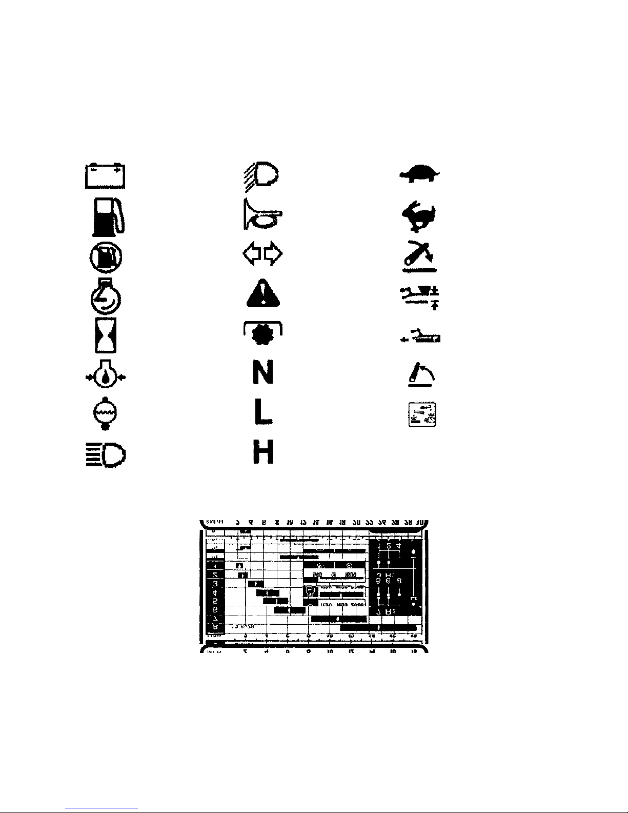
UNIVERSAL SYMBOLS
As a guide to the operation of your tractor, various universal symbols have been utilized on the instruments,
controls, switches and fuse box. The symbols are shown below with an indication of their meaning.
Alternator/Dynamo
Charge
Fuel level
Fuel shut-off
Enginespeed
(rev/min × 100)
Hoursrecorded
Engineoil pressure
Enginecoolant
temperature
Headlight
mainbeam
Headlightdipped
beam
Horn
TurnSignals
Warning!
P.T.O.
Transmissionin
neutral
Lowtransmission
range
Hightransmission
range
Slow or low setting
Fast or high setting
Linkagelower
PositionControl
DraftControl
Linkageraise
Warning!Corrosive
substance
Thedecal shown aboveissimilar to thatfitted next totheinstrument panel ofyour tractor andgraphically illustrates
the approximate tractor road speed at three alternative engine speeds. The decal also shows the engine speed at
which P.T.O. speed of 540 RPM is obtained. Accurate road speed charts are provided at the end of Section C.
ix
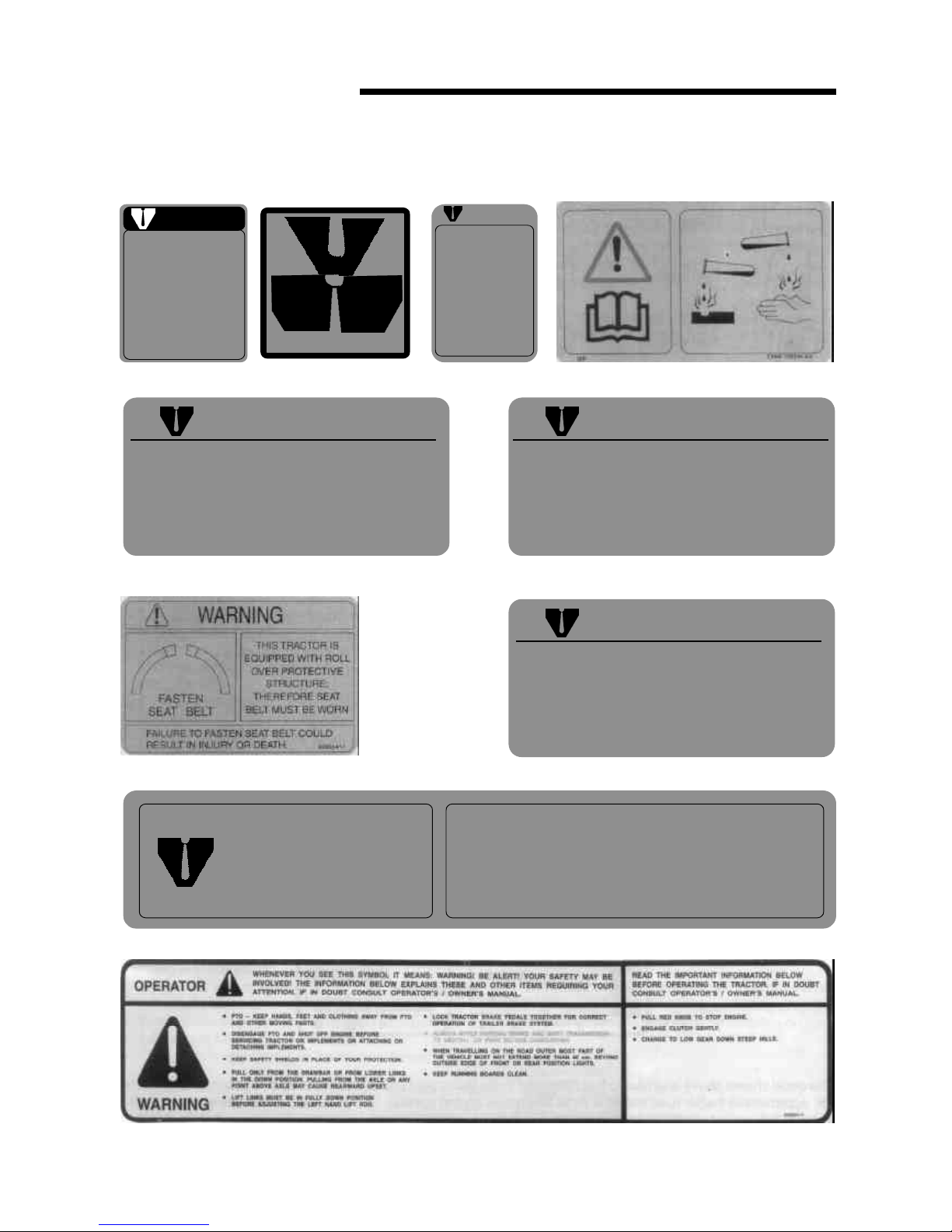
SAFETY SYMBOLS
x
CAUTION
DO NOT OPERATE
UNTILL YOU READ THE OWNERS MANUAL
IF YOU DID NOT RECEIVE A COPY ONE MAY BE OBTAINED FROM
YOUR AUTHORISED DEALER
l
Pull only from drawbar. Pulling
from other points can cause rear
overturn.
l
Do not operate with unshielded PTO.
l
Disangage PTO and stop engine before
servicing tractor or implements or
attaching and detaching implements.
l
Position drawbar at 14" from end of
PTO shaft to drawbar hole for 540 RPM.
l
When towing equipment use a safety
chain.
FAILURE TO FOLLOW ANY OF THE INSTRUCTIONS
ABOVE CAN CAUSE SERIOUS INJURY TO THE
OPERATOR OR OTHER PERSONS.
WARNING WARNING
AVOID POSSIBLE INJURY
OR DEATH FROM A
MACHINE RUNAWAY
1. Donotstartengine byshorting
across starter terminals.
Machinewill statrt ingear and
move if normal starting cir-
cuitry is bypassed.
2. Startengine only fromopera-
tors seat with transmission in
neutral or park.
NEVER start enigine while
standing on the ground.
CAUTION
AFTER FIRST HOUR OF OPERATION FRONT
AND REAR WHEEL LUG NUTS AND BOLTS
SHOULD BE CHECKED FOR PROPER
TORQUE - THERE AFTER CHECK DAILY.
82835415
WARNING
THE DIFFERENTIAL LOCK IS PRO-
VIDED FOR USE ON SLIPPERY SUR-
FACES, IT MUST NOT BE USED ON
THE ROAD.
WARNING TO AVOID INJURY, KEEP
THIS GUARD IN PLACE
SAFETY INSTRUCTIONS
E2NN-94000R86-AA
82835419
1178500AA

CONTROLS,
INSTRUMENTS
and OPERATION
Thefollowing pages in thissection detail thelocationand function ofthe various instruments, switchesand controls
on your tractor. Even if you operate other tractors, you should read through this section of the Manual and ensure
thatyouare thoroughly familiar withthe location and function ofall the features ofyournew tractor. Do notstartthe
engine or attempt to drive or operate the tractor until you are fully accustomed to all the controls. It is too late to
learn once the tractor is moving. If in doubt about any aspect of operation of the tractor, consult your Authorized
Dealer.Reference totractor modelsor equipmentnotavailable inyour territoryor tooptions oraccessoriesnot fitted
on your tractor should be ignored.
Particular attention should be paid to the recommendations for running-in to ensure that your tractor will give the
long and dependable service for which it was designed.
See Section B for the routine lubrication and maintenance requirements. The specification of your tractor will be
found in Section C.
SECTION A
1
OPERATOR’S SEAT
Before operating the tractor, it is important to adjust
theseatto the most comfortableposition. See Figure 1
for details.
To achieve the optimum suspension setting, sit in the
seat and turn the suspension adjuster knob until the
weight indicators on the seat frame align.
Press down the horizontal travel adjustment lever and
movetheseat forwardorbackward, asrequired.Further
seat travel is possible after loosening the two seat
mountingboltsthat secure the seatbase to the tractor.
Seat height is adjusted after loosening the two knobs
on both sides of the seat frame.
NOTE: Do not use solvents to clean the seat. Use
warm water with a little detergent added.
SEAT BELT, SAFETY FRAME OR ROLL BAR
(where fitted)
WARNING : Tractors equipped with a safety
frame or roll bar also have a seat belt fitted.
Always use the seat belt with a safety frame or roll-bar
installed. Do not use a seat belt if the tractor is not
equipped with a safety frame or roll bar.
To lengthen the belt, tip the buckle away from the belt
and pull on the buckle. With the belt fastened around
you, pull the free end of the belt until it is a snug fit.
The belt may be sponged with clean, soapy water. Do
1. Seat
1. Suspension adjuster knob
2. Weight indicators
3. Horizontal travel adjustment lever
4. Seat mounting bolts
5. Height adjustment knob
not use solvents, bleach or dye on the belt as a these
chemicals will weaken the webbing. Replace the belt
whenitshowssignsof fraying,damageor generalwear.
If your tractor is fitted with a safety frame or roll bar, it
must be maintained in a serviceable condition.
If your tractor is fitted with a front end loader, it is
recommended that a canopy be fitted to protect the
operator from objects that may fall from the loader
bucket.
WARNING: Do not attach chains or ropes to
thesafetyframeorrollbarforpullingpurposesince
thetractormaytipback-wards.Alwayspullfromthetractor
drawbar.Becareful whendrivingthrough dooropenings
or under low overhead objects. Make sure that there is
sufficientoverhead clearance fortheroll bar.
INSTRUMENTS AND CONTROLS
The following text describes the various gauges,
switches and warning lights installed on your tractor,
See Figure 2A and 2B.
Tachometer
Thetachometerindicatesenginerevolutions perminute.
Eachdivision on thescalerepresents 100 rev/min.-eg.
with the needle indicating ‘20’ the engine is running at
2000rev/min.
Theyellow mark on thetachometer scale indicates the
engine speed at which the standard P.T.O. speed of
540 rev/min is obtained.
Thetachometer also records thetotal number of hours
that the tractor has operated, based on an average
engine speed of 1600 rev/min. If the engine is run at a
speedlower than1600 rev/minthen thetachometerwill
accumulatehoursatarate slowerthan realtime.Higher
enginespeedswillcausethetachometerto accumulate
hours at a rate faster than real time.
The hours recorded should be used as a guide to
determine hours servicing intervals. (see Section B of
this Manual).
Engine Coolant Temperature Gauge
The gauge indicates the temperature of the engine
coolant. If the needle enters the red area of the gauge
while the engine is running, stop the engine and
investigate the cause.
NOTE :When the key-start switch is turned off, the
gauge needle will assume a random position.
CONTROL, INSTRUMENTS AND OPERATION
2

2A. Single Instrument Cluster
1. Tachometer
2. Engine coolant temperature gauge
3. Engine Oil Pressure Warning Light
4. Fuel Gauge
5. LH Turn Signal Indicator
6. RH Turn Signal Indicator
7. Battery Charging Indicator
8. Hazard Warning Light Switch
9. Air Restriction Warning Light
10. Engine Stop Control
11. Tractor Light Switch
12. Key Start Switch
13. Horn Switch
14. Hand Throttle
15. Turn Signal Indicator Switch
16. Plough Lamp Switch
EngineOilPressure Warning Light
The red warning light on the instrumentpanel indicates
lowengineoilpressureandshouldextinguishimmediately
after the engine is started, and is only operative with the
key start switch in the ‘ON’ position.
NOTE :If the light comes on while engine is running,
stop the engine immediately and investigate the cause.
Thelightindicateslowoilpressureandisnotanindication
of oil level. The engine oil level must still be checked
daily by means of the dipstick.
Hand Throttle
Withtheengine running, pull thethrottle lever rearwards
toprogressivelyincreaseenginespeed.Pushthethrottle
leverforwardtodecreasetheenginespeed.
Hazard Warning Light Switch
Press the switch to operate both turn signals
simultaneously. The switch, which is internally
illuminated, will flash in unison with the turn signals
and the turn signal indicator lights on the instrument
panel.
Indicator Ligthss
The upper indicator light of the pair will illuminate when
headlampmainbeamisselected.Wheneitheroftheturn
signal is operated, the lower indicator light will flash in
unison with the turn signals.
In some territories, where only single beam (dipped
beam) headlamps are fitted, the upper indicator light
will flash in unison with the turn signals when either of
the turn signal is operated. If, however, the tractor is
also equipped with a 7 pin rear trailer socket, the lower
indicator light will flash in unison with the turn signals
of the trailer when either of the turn signal is operated.
The turn signal indicator lights will also flash in unison
with the turn signals whenever the hazard switch is
operated.
NOTE : Please check with your Authorized Dealer on
which system is fitted on your Tractor.
Tractor Lights Switch
The lights switch is of the push-pull type and has three
positions:
Fully in :lights OFF
Midway :side, rear and instrument lights ‘ON’
Fully out :side,rear, instrument andheadlights‘ON’
Engine Stop Control
Pull the stop control knob fully out and hold it in that
position to cut off the fuel supply to the injectors and
stoptheengine.Theknobmustbe pushedfullyinbefore
restarting the engine.
SECTION A
3
2B. Instrument Panel
(Steering wheel removed)
4
7
5
39
2
6
1
10
11
12
13
14
15
16 8

4
Key-Start Switch
The key operated switch actuates the starting motor.
See ‘Starting The Engine’ for the correct operating
procedure.
Road Speed Decal
Thedecalwhichisalsoillustratedon PageIX,showsthe
approximatetractorspeedinallgearratios.Accurateroad
speed charts are provided at the end of section C.
Charging Indicator
Theredwarninglighton theinstrument clusterindicates
thatthe alternatorisnotchargingthebatteryand should
extinguish when the engine speed is increased above
idle.
Fuel Gauge
The gauge indicates the level of fuel in the tank and is
only operative with the key-start switch in the ‘ON’
position.
NOTE :When the key-start switch is turned off the
gaugeneedle may assumea random positionand may
indicatesa fuel levelgreater than thetrue level. Always
check the fuel level with the key-start switch on.
Air Restriction Warning Light (where fitted)
When this lamp lights up, clean or replace the outer
elementofdryaircleaner.Iflightcomes onduringtractor
operation when replacement of element is not
immediatelypossible,justcleantheelementandreduce
theenginespeed soontopreventthelampfromlighting.
Seven-Terminal Trailer Socket (where fitted)
Thissocketallowslights,turnsignalsandotherelectrical
equipment on a trailer or impliment to be connected.
This is fitted at the rear of driver’s seat.
Alwaysuseadditionallighting onthemountedimplement
if this conceals the turn signals and other lights at the
rear of the tractor.
CONTROL, INSTRUMENTS AND OPERATION
STARTING THE ENGINE
A five-position key-start switch is installed on all the
tractors. For starting in temperatures down to –180C
(00F) the thermostart option may also be installed,
Basically the thermostart consists of an electrically
heatedelement inthe air intaken manifoldwhich, when
operated, ignites a measure of diesel fuel and
introduces it into the combustion chamber. With the
thermostart installed, all the five positions of the
keystart switch are connected as shown in Figure 3.
However, if the automatic thermostart is not installed,
the starting motor operates at position (4) while as
position (5) is left unconnected (see Figure 3).
IMPORTANT : Never push or tow the tractor to start
the engine. Doing so may overstress the drive train.
NOTE: A safety start switch prevents operation of the
startingmotor unless the transmissionrange lever is in
theneutral(N) position.
Beforestartingthe engine,alwayscarry outthefollowing
procedure:
lSitinthedriver’sseatandensurethattheparkingbrake
latch is firmly applied.
lPush the stop control knob fully in.
lEnsure that both gearshift levers are in neutral and
thattheP.T.O.leverisinthedisengagedposition.
lMovebothhydrauliclift control levers fully forward.
lPlace the remote control valve levers in neutral.
WARNING:Startthetractoronlyfromthedriver’s
seat. If the key-start switch is bypassed, the
engine may start inadvertently with a gear selected and
cause sudden and unexpected movement of the tractor
or a tractor runaway. Wear eye protection when starting
thetractor with jumpleads or whencharging the battery.
For standard tractors (without automatic
thermostart)
lOpen the hand throttle halfway, depress the clutch
to ease the load on the starter motor and turn the
key-start switch fully clockwise to position (4) to
operate the starting motor. Crank the engine until it
startsbutdo notoperatethestartingmotorformore
than 40 seconds and then allow the key to return to
position(3).
lReturnthethrottletotheidleposition andcheckthat
allwarninglightsextinguishandgaugereadingsare
normal.
Connection WireColour
1. Ground Brown
2. ParkingRH Grey-Red
3. Turnsingal LH Black-White
4. Brake light Red-White
5. TurnsignalRH Black-Green
6. ParkingLH Grey-Red
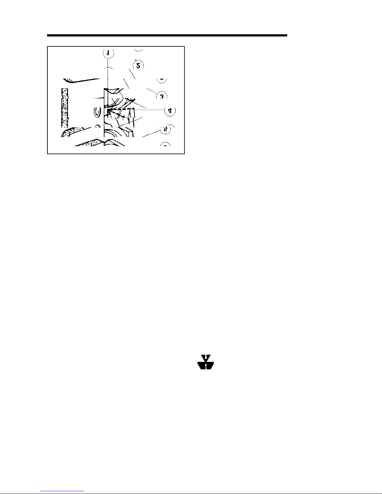
3. Key-startSwitch
1. Electrical equipment ‘OFF’
2. Accessories ‘ON’
3. Warning lights and instruments ‘ON’
4. Thermostart heater ‘ON’ (where fitted), or
Starting motor operates (where thermostart is
not fitted).
5. Starting motor operates (where thermostart is
fitted), or
Unconnected (where thermostart is not fitted).
For tractors fitted with automatic
thermostart:
lInwarmweather,orwhentheengineishot,depress
theclutchandturnthekeystartswitchfullyclockwise
to position (5). Operate the starting motor until the
engine starts or for a maximum of 40 seconds and
then allow the key to return to position (3).
lIn cold weather with the engine cold, depress the
clutch and turn the key-start switch to position (4),
holdfor20-30secondsandthenturnfullyclockwise
to position (5). Operate the starter until the engine
starts or for a maximum of 30 seconds.
lReturn the throttle to the idle position and check
thatallwarninglightsextinguishandgaugereadings
arenormal.
NOTE : If the engine fails to start, repeat the procedure,
after waiting for 1-2 minutes. If the thermo-start is fitted,
thekeyshouldbeheldatposition(4)onlyfor7-10seconds
when attempting to restart the tractor.
STARTING THE TRACTOR WITH JUMP LEADS
If it is necessary to use jump leads (booster cables) to
start the tractor, proceed as follows:
lConnectoneend ofthered jumpleadtothetractor
battery positive (+) terminal and the other end to
the auxiliary battery positive (+) terminal.
lConnect one end of the black jump lead to the
auxiliary battery negative (-) terminal and the other
end to a suitable projection on the tractor engine
block. Follow the starting procedure previously
described.
lWhenthe enginestartsallow itto runatidle speed,
turn on all electrical equipment (Lights etc.) then,
disconnect the jump leads in the reverse order to
theconnectingprocedure.Thiswillhelpprotectthe
alternatorfrompossibledamageduetoextremeload
changes.
NOTE : When using an auxiliary battery to start the
engine,ensurethatthepolarityofthejumpleadsiscorrect
- positive to positive, negative to negative otherwise
thealternatormay bedamaged.
STOPPING THE ENGINE
Tostop theengine, carryoutthe followingprocedure:
lSit in the driver’s seat and close the throttle.
lEnsurethattheparkingbrakelatchisfirmlyapplied.
lEnsurethat both gearshiftlevers are inneutral and
thattheP.T.O.leveris inthe disengagedposition.
lPullthestop controlknob fullyoutand turnthekey-
start switch off.
lMovethehydraulicliftcontrolleversfullyforwardto
lowerall hydraulic equipmentto theground.
lMove the remote control valve levers fully forward
andthenfullyrearwardbeforeplacingtheminneutral
position.
WARNING :Check the area beneath the
equipmenttoensurethatnoinjuryordamagewill
becausedwhenequipmentislowered.
PARKING BRAKE
Toparkingbrakeconsistsofa latchthat isusedtosecure
the foot brakes in the applied position. (See Figure 4).
SECTION A
5

4. Parking Brake
1. T-handle
Tooperatethe parking brake, lockthe brakes together
(see the following text titled ‘Foot-brakes’). Apply the
footbrakes, pullup theT-handle androtate onequarter
turn.To free theparking brake, rotatethe T-handle one
quarterturn andrelease.Momentarily depressthe foot
brakestodisengage theratched.In Figure4,theparking
brake is shown in the applied position.
IMPORTANT : Ensure that the parking brake is fully
releasedbeforedriving off.
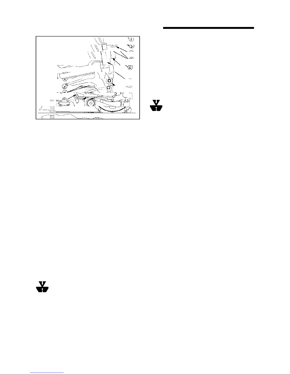
FOOT CONTROLS
For details of foot operated controls, refer to Figure 5
and the following text.
Foot Brakes
Thefoot brake pedals,Figure 5,activate therear wheel
brakes and may be operated independently, to aid
turning in confined spaces or together for normal
stopping.When operating in thefield, the brake pedals
may be unlocked. However, due to the close proximity
of the pedals to one another, it is still possible to apply
bothbrakestogether,whenrequired.
WARNING : For your safety, always lock the
brake pedals together when travelling at
transport speeds, or on a highway or if a trailer is
attached.To lockthe pedals together,slide thelatch (5)
across to engage in the hole in the underside of the
right-handpedal, as shown.
Foot Accelerator
The foot accelerator, Figure 5, may be used
independently of the hand throttle to control the speed
of the tractor. It is recommended that you use the foot
acceleratorwhen driving on thehighway.
NOTE :Whenit is requiredto use thefoot accelerator,
set the hand throttle to the idle position (fully forward).
Differential Lock
In field conditions including wheel slip, hold down the
differential lock pedal, Figure 5, until the lock is felt to
engage. The lock will automatically disengage when
traction at the rear wheels equalizes.
Ifconditionscausearear wheelto spinatspeed,reduce
theengine speedto idlebefore engagingthedifferential
lock.
WARNING :Neverengagethedifferentiallock
atspeedsabove5mph (8kmph) orwhenturning
the tractor. When engaged, the lock will prevent the
tractorfromturning.
Clutch
Whenthe clutch pedal,Figure5, is depressedthe drive
betweentheengineandtransmissionwillbedisengaged.
Usethe clutch pedaltotransfer engine powersmoothly
tothedriving wheels when movingoff from a standstill.
Alwaysdepresstheclutchpedaltoengageordisengage
a gear ratio or when operating transmission P.T.O. or
live P.T.O. (see Power Take Off in this section of the
Manual)
NOTE :Avoid resting your foot on the clutch pedal
whenoperating the tractor.Such actionwill leadto early
clutch failure.
5. FootControls
1. Brake pedals
2. Foot accelerator
3. Differential lock pedal
4. Clutch pedal
5. Locking latch
6
CONTROL, INSTRUMENTS AND OPERATION

TRANSMISSION
Thetransmissionis of theconstantmesh type andhas
eightforwardand two reverse speed ratios.
WARNING :To prevent inadvertent tractor
movement, avoid accidental contact with the
gearshift levers. Always stop the engine, firmly apply
the parking brake and place both gearshift levers in
neutral before dismounting from the tractor. A safety
switch prevent operation of the starting motor unless
the right-hand lever is in the neutral (N) position.
The gearshift levers protrude from the center of the
transmission,beneaththe steering wheel.
The left-hand gearshift lever (main) is used to select
any one of four forward or one reverse gear ratio. The
right-handlever (range) isused to selectthe high (H)or
low(L)rangewhichhastheeffectofdoublingthenumber
of available gear ratios. Stop the tractor and fully
depress the clutch before moving either of the gear
levers. See Figure 6 for the gear shift positions.
IMPORTANT : When towing the tractor, it is essential
that the transmission main (right-hand) lever is kept in
the neutral (N) position. Non compliance may result in
damage to transmission components.
Avoid overloading the engine. Operating in too high a
gear under heavy load may cause excessive engine
overloading. Overloading occurs when the engine will
not respond to a throttle increase.
Usethe lowergearratios whenpulling heavy loadsand
avoidcontinuousoperation at constant engine speeds.
Operating the tractor in too low a gear with a light load
andhigh enginespeed willwaste fuel.You willsave fuel
andminimize enginewear byselectingthe correctgear
ratio for each particular operation.
Checkthe instruments frequentlyandkeep the radiator
and various oil reservoirs filled to the recommended
levels.
POWER TAKE-OFF (P.T.O.)
The power take-off (P.T.O.) on your tractor transfers
engine power directly to mounted or trailed equipment
via a splined shaft at the rear of the tractor.
The P.T.O. shaft is a 6-spline, 1.375 in (34.9 mm)
diameter shaft designed for 540 rev/min operation, the
speed at which most P.T.O. actuated equipment are
designedto run.
Toobtain540 rev/minatthe P.T.O.,setthetractorengine
speed to 1600 rev/min if your tractor is equipped with
transmissionP.T.O.,or1800rev/minforlivePTOmodels.
FormostP.T.O.operationsthegroundspeedofthetractor
is controlled by selection of the appropriate gear ratio
whilemaintaining the correctP.T.O.speed by usingthe
throttle.
Attaching P.T.O. Driven Equipment
WARNING :Before attaching, detaching or
workingonP.T.O.drivenequipment,thefollowing
precautions must be taken :-
*Firmly apply the parking brake.
*Ensurethat bothgearshift leversare inneutral and
thattheP.T.O.leveris inthedisengagedposition.
*Stop the engine.
*Ensurethat the P.T.O. shaft hasstoppedturning.
6. Gear Shift Lever Positions
H = High Range
L = Low Range
N = Neutral
R = Reverse
SECTION A
Rangelever Main gear shift lever
RUNNING-IN-PROCEDURE
Yournewtractorwillprovidelonganddependableservice
ifgiven proper careduringthe first 50hours running-in-
period and if serviced at the recommended intervals.
Avoid prolonged operation at either high or low engine
speeds without a load on the engine.
7
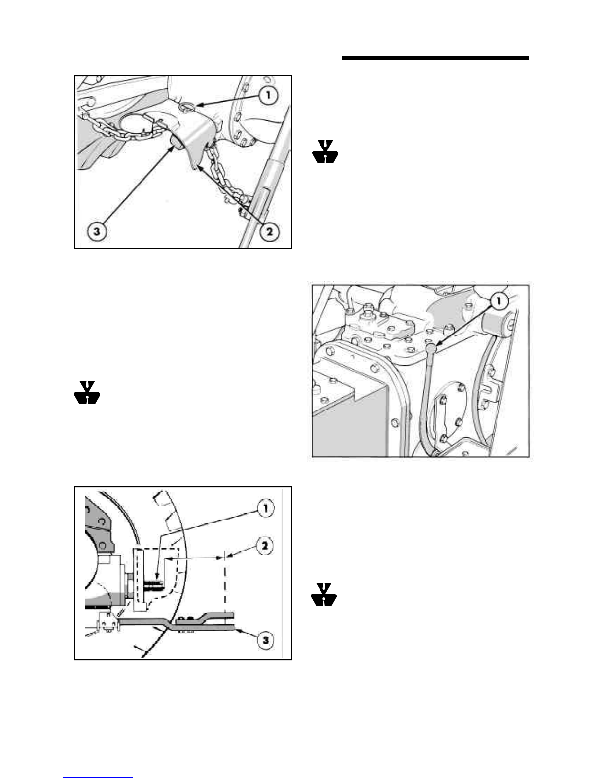
ToconnectP.T.O.drivenequipment tothe P.T.O.shaft,
removethe guard (wherefitted) which issecured to the
rear axle center housing by a linch pin, as shown in
Figure7.Unscrewandremove theP.T.O.cap andstore
inthe toolbox. Attach theimplement to the P.T.O.shaft
andreinstallthe guard.
WARNING :The guard serves as a support
for drive line shields used with Pull-type P.T.O.
driven equipment and also provides you safety.
If P.T.O. driven equipment is attached to the drawbar
thenthe drawbarshould be setto theextended position
so that the horizontal distance between the end of the
P.T.O.shaftandthepin holein theend ofthedrawbaris
at least 14.9 in (378 mm.) See figure 8.
IMPORTANT :After attaching mounted equipment
carefully raise and lower them using Position Control
LeverandcheckclearancesandP.T.O.shaftsliderange
/articulation. Whenattaching trailed equipment,ensure
the drawbar is correctly set.
WARNING :Do not approach or work on the
P.T.O. shaft or equipment with the P.T.O. in
motion. Block all four wheels when carrying out
stationaryP.T.O. work.
OPERATING THE P.T.O.
Transmission P.T.O. (where fitted)
To operate transmission P.T.O., start the engine, fully
depress the clutch pedal and pull the P.T.O. selector
lever,Figure9,rearwards.Set theenginespeed to1600
rev/min. then release the clutch pedal.
7. Power Take-Off
1. Linch pin
2. Guard
3. P.T.O.cap
8. Drawbar setting
1. P.T.O.outputshaft
2. Horizontal distance - shaft to hitch pin
3. Drawbar
9. P.T.O.Selector
1. P.T.O.selectorlever
Transmission P.T.O. may be engaged or disengaged
whether the tractor is moving or stationary. When
stoppingthe tractor, the actionof depressing the clutch
pedal will stop rotation of the P.T.O. output shaft.
IMPORTANT: Always depresstheclutchpedalbefore
engagingordis-engagingtheP.T.O. topreventdamage
toP.T.O.components.
WARNING :To avoid inadvertent movement
oftheimplement,disengage theP.T.O.aftereach
use.
Live PTO (where fitted)
LiveP.T.O.operatesinasimilarmannertoTransmission
P.T.O.exceptthatatwo stageclutch permitsthetractor
tobestoppedwhileallowing theP.T.O. shafttocontinue
turning. With the clutch pedal fully depressed neither
thetractor nor theP.T.O.shaft is operable.
8
CONTROL, INSTRUMENTS AND OPERATION
To operate Live P.T.O., start the engine, fully depress
the clutch and pull the P.T.O. selector lever, Figure 9,
rearwardstoengagetheP.T.O.
Set the engine speed at 1800 rev/min and release the
clutchpedaltothehalfway positiontoactuate theP.T.O.
output shaft.
With a gear selected, fully release the clutch pedal to
runthetractor.
Tostop thetractor,depress theclutchpedal tothe mid-
positionand tostop the P.T.O.output shaftdepress the
pedalfully.
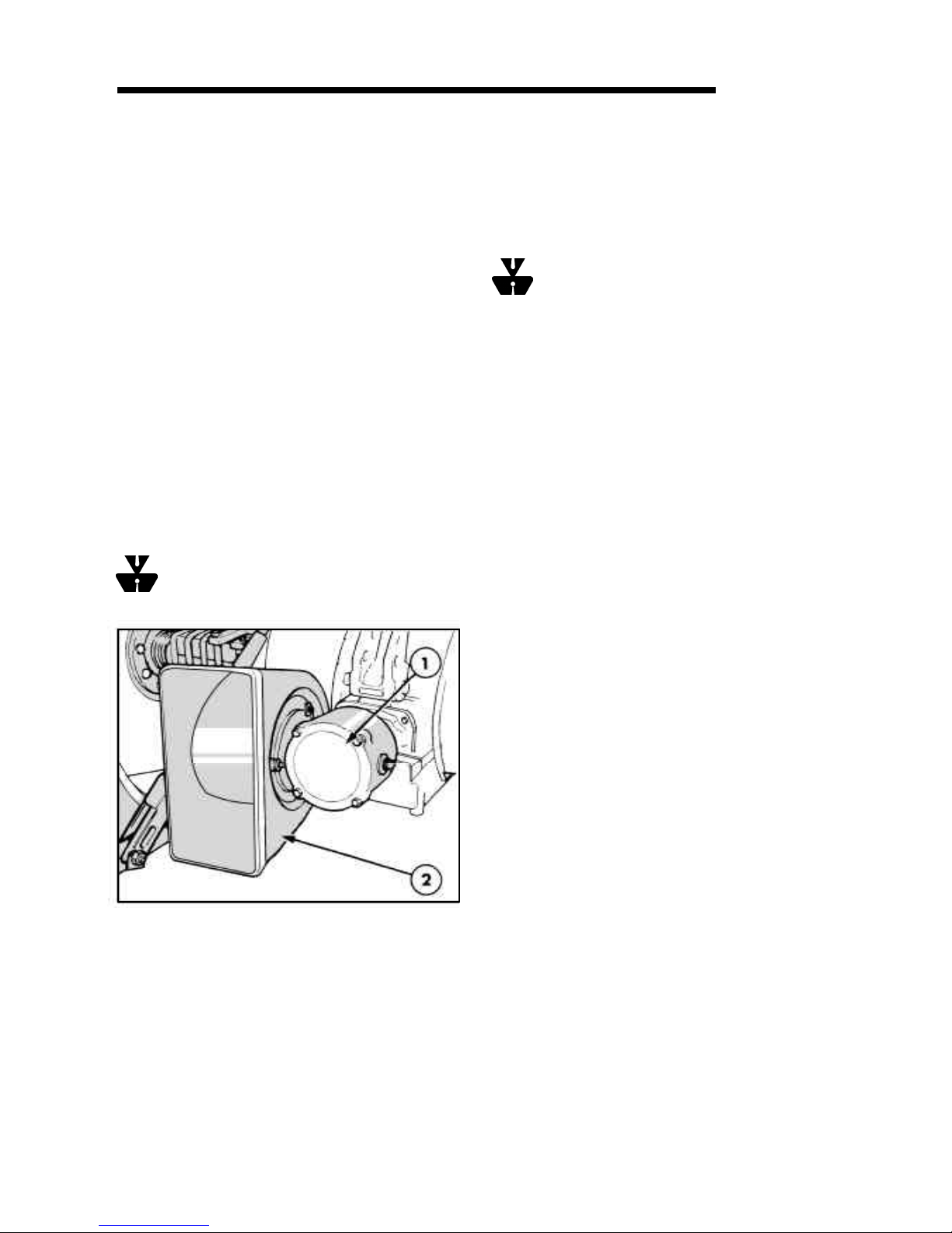
BELT PULLEY (where provided)
The belt pulley, which is driven by the P.T.O . output
shaft, should be installed as shown in Figure 10.
Prior to installation, remove the drawbar and drawbar
hangerto provide the maximumclearance for the drive
belt.
To install the belt pulley, remove the P.T.O. safety cap
and guard and the four bolts securing the check chain
bracketsto the rearaxle center housing.Install the belt
pulleyon the P.T.O.shaft using thefour bolts provided.
WARNING : Toavoid injury, alwaysuse abelt
guardwhenever using the beltpulley.
lHanga chainor leananiron baragainst thetractor
to earth static electricity.
lStart the engine and engage the P.T.O. The
recommended belt speed is 3000-3200 ft/min
(15.3-16.3 m/sec). To obtain this speed set the
engine speed at 2000 rev/min.
WARNING: Never attempt to re-fit or adjust a
belt in motion. Never approach a moving belt
when wearing loose clothing. Apply the parking brake,
place both gearshift levers in neutral and block all four
wheelsbefore operating thebeltpulley.
HYDRAULIC SYSTEM
Your tractor is equipped with a hydraulic system
providing accurate and sensitive control over a wide
rangeof operating conditions.
Twodistinctsystems are incorporated
1. UpperLink Draft Control.
2. PositionControl.
The type of control selected will depend on the type of
implement in use and the operating conditions.
Draft Control is most suitable for mounted
implements operating in the ground. Changes in the
workingdepth orsoil resistancecausethe draftloading
onthe implementto increaseordecrease. Thischange
in draft loading is sensed through the top link of the
three-pointlinkage and the hydraulicsystemresponds
byraising or loweringthe implement torestore the draft
loading. In this way a uniform draft load is maintained
on the implement. The system responds to both upper
link compression and tension loads and is, thus,
described as a double-acting system.
Position Control provides accurate and sensitive
controlofimplementssuchas sprayers,rakes,mowers,
etc., that operate above the ground. Position Control
would not normally be used with ground engaging
equipment unless it is essential to maintain a constant
depth regardless of the draft load.
Thetractorhasadualleversystem, i.e.,separatelevers
forDraft and Position Controlfunctions. See Figure 11.
TheDraftand Position Control levers areusedto raise
or lower the three-point linkage (and implement) to the
requiredheight orworking depth.
To Operate the Belt Pulley
lFully raiseand secure the lower links.
lAlignthetractorwiththeequipmentto obtainfullwidth
contactonbothpulleyswithoutthebeltcontactingany
otherpart of the tractororequipment.
lApplytheparkingbrakeandblockallwheelstoprevent
tractormovement due tovibration.
SECTION A
10. Belt Pulley
1. Belt pulley
2. Belt guard
9
Table of contents


