ESI CLIMB1-SLV User manual

ASSEMBLY AND ADJUSTMENT
CLIMB1
Model CLIMB1-SLV
SIT/STAND WORKSTATION
CLIMB1 Rev B 11/17

1
PLEASE REVIEW these instructions before beginning the assembly and adjustment procedures. Check that
all the parts and tools listed below were provided with your order. Contact your supplier if any materials are
missing. Do not discard the packaging until content that the product operates to your satisfaction.
CLIMB1 PARTS AND TOOLS
Base and Column Assembly (1)
Keyboard Platform (1)
Writing Platform Assembly (1) VESA Mount (1)
PARTS AND TOOLS PROVIDED
CAUTION: Hand-tighten screws only. Do not use power tools.
Nut (2) Star Washer (2)
5/8" Wrench (1)
1/2" Socket Wrench (2)
Keyboard Hole Plug (2)
M6x15mm Screw (2)M6x10mm Screw (2)
M4x12mm Screw (4) 3mm Allen Key (1) 6mm Allen Key (1)4mm Allen Key (1)
ADDITIONAL TOOLS REQUIRED
• Phillips screwdriver

2
Clamp Base and Column Assembly to Work Surface
The base clamp requires 4" of clearance under the work surface for attachment. The clamp
accommodates work surface thicknesses from .75" to 3.3" (20mm to 80mm).
Adjust Clamp, If Necessary
• The clamp as shipped can be attached to work surfaces from
1¾" to 3.3" thick.
• For thinner work surface thicknesses, the three screws on the
clamp portion may be removed and the clamp re-attached
in one of the other three sets of holes. Each set of holes is
approximately 1" apart.
Attach Clamp
• Position the clamp at the desired location, with the back
of the clamp ush against the back of the work surface.
• Use the provided 5/8" wrench to tighten the clamp bolts.
IMPORTANT: Be sure the clamp is securely tightened.
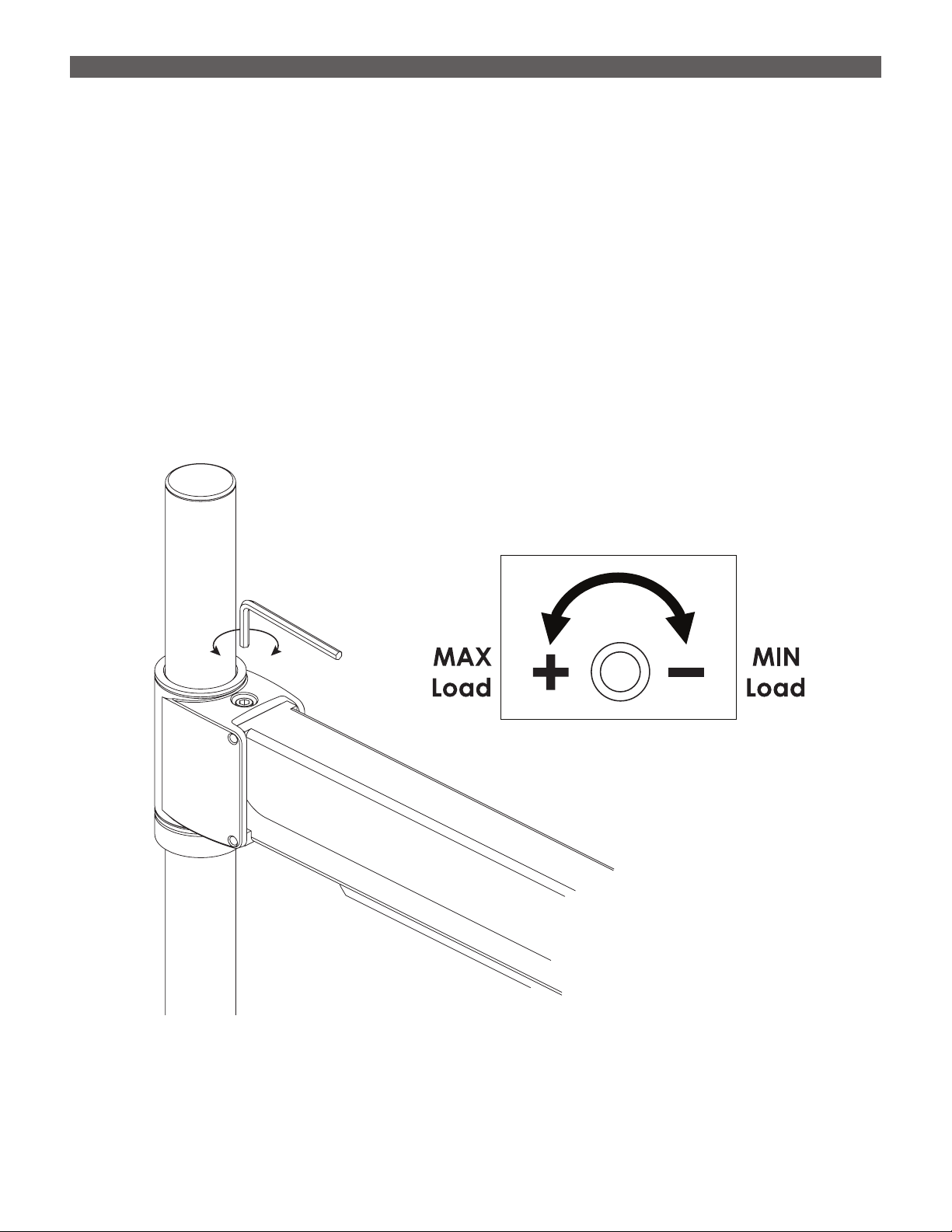
Adjust Height of Main Assembly Arm
TIP: It is benecial to have a helper to support the main
assembly arm when making this adjustment.
• Use the 3mm Allen key to loosen the two set screws in the
locking ring.
• Move the locking ring up or down to set the height of the
main assembly arm. The main assembly arm rests on top of
the locking ring.
• Tighten the two set screws to secure the locking ring/main
assembly arm in the desired position.
— This adjustment can be ne-tuned at any time. It is
especially important to have a helper hold the main
assembly arm after the monitor, keyboard, etc. are in
position.
WARNING: Do not engage the paddle until after
assembly is complete. With no load on it, the main
assembly arm could raise quickly and suddenly.
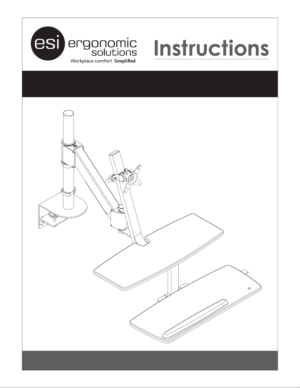
ASSEMBLY CLIMB1
Remove Screws
to Adjust Clamp
.75"
3.3"
Tighten
Securely!
Work Surface
5
/8" Wrench
Locking
Ring
3mm
Allen Key
Set
Screws

3
CLIMB1 ASSEMBLY
Right-Side Mouse Left-Side Mouse
Attach Writing Platform to Main Assembly Arm
• Insert the threaded bolts on the writing platform
through the holes on the mount at the end of the
main assembly arm.
• Secure the bolts using the nuts and star washers
provided, as shown. Tighten the nuts using the ½"
socket wrench.
— Be sure the at side of the nut is against the star
washer.
Change Side of Keyboard Palm Rest, If Desired
By default, the keyboard palm rest is on the left side for a right-side mouse. If desired, it may be changed to
the right side for a left-side mouse.
• Using the 4mm Allen key, remove the screws holding the palm rest from the underside of the keyboard
platform. Remove the plug from the far right-side hole.
• Re-install the screws to attach the palm rest to the right side of the keyboard platform. Use one of the new
plugs provided to conceal the exposed left-side hole.
Nut and
Star Washer
Main
Assembly
Arm
Writing
Platform
½" Socket
Wrench

4
Move Screws for
Left-Side Paddle
Paddle on
Right Side
(Default)
ASSEMBLY CLIMB1
Attach the Paddle to the Keyboard Platform
By default, the paddle is attached to
the right side of the keyboard platform,
where there are two holes for the
M6x15 screws. If desired, the two
screws on the left side of the
platform may be moved to the
right side so that the paddle can
be attached on the left side.
• Use the 4mm Allen key to
secure the paddle on the left
or right side with the M6x15 screws.
Attach the Keyboard Platform
• Using the 4mm Allen key, attach the keyboard platform with two M6x10 screws,
as shown. Tighten securely.
• After attaching the keyboard platform, route the paddle cable through the
clips on the underside of the writing platform.
Keyboard
Platform
Writing
Platform
M6x10
Route Paddle
Cable Through
Clips

5
CLIMB1 ASSEMBLY
Attach VESA Mount to Writing Platform Column
• Loosen the knobs on each side of the VESA
mount to allow the mount to t over the writing
platform column.
• With the open slots on top, slide the VESA mount
over the column and position at the desired
height. Tighten the knobs.
— The height of the VESA mount may be
adjusted at any time by loosening the knobs.
Attach VESA Screws to Monitor
• Place the monitor face down on a at surface.
• Use the 3mm Allen key to attach M4x12 VESA screws into
the top two holes only.
— Do not tighten the screws all they way. Leave ¼"
exposed for attachment to the VESA mount.
Tighten
Knobs
Loosen
Knobs
Open
Slots
on Top
VESA Mount
M4x12
VESA
Screw
¼" Exposed
Monitor
(Face Down)
Top Two
Holes Only

6
ASSEMBLY CLIMB1
Attach Monitor to VESA Mount
• Hang the monitor on the VESA mount.
— If the outer set of VESA holes was used (100mm apart), hang the two top screws in the open slots.
— If the inner set of holes was used (75mm apart), insert the two screw heads through the top inner holes
and hang the monitor from those screws.
• Attach the bottom of the VESA mount using the remaining two M4x12 screws and the 3mm Allen key.
• Tighten all four screws securely.
Cable Management
After positioning the keyboard and mouse, organize
the cables. Cables must not interfere with product
operation or with the user’s ergonomic enjoyment of
the unit.
• Remove the cable cover using a Phillips screwdriver.
• Re-install the cable cover with the monitor and
keyboard cables captured.
• Use the pole clip to route the cables down to the
CPU or power outlet.
3mm Allen Key
Cable
Cover
Pole
Clip

7
CLIMB1 ADJUSTMENT
Test Operation
• Depress the paddle lever. Raise and lower the unit through its full range of movement.
• Position the unit so the column is at a 90° angle. If necessary to ne tune operation of the product, make
one or both of the adjustments shown on page 8.
CAUTION: Keep both hands on the keyboard platform to control the rate of movement when depressing
the paddle lever.
Adjust Angle of Monitor, If Necessary
• Remove the plastic caps from the sides of the VESA mount to allow access to the bolt and nut.
• Use the ½" socket wrench to loosen the bolt and nut (counterclockwise). Tilt the VESA mount and monitor
to the desired viewing angle.
• After the adjustment is complete, tighten the bolt and nut with the socket wrench (clockwise). Replace
the caps.
½" Socket
Wrench
Cap

8
If Necessary, Adjust for Load Weight
This adjustment can be used to maximize ease of operation. When operating this product, the main
assembly arm should move easily to any position and hold that position.
• If the arm is difcult to raise or lowers too easily, increase the load adjustment (+).
• If the arm is difcult to lower or raises too easily, decrease the load adjustment (
–
).
• Use the 6mm Allen key to turn the adjusting screw — counterclockwise to increase load, clockwise to
decrease it.
• Test operation and re-adjust as necessary.
CAUTION: Do not over-tension the MAX (+) adjustment.
ADJUSTMENT CLIMB1
+–
6mm Allen
Wrench

800.833.3746 esiergo.com
© 2017 ESI Ergonomic Solutions. All rights reserved. CLIMB1 Rev B 11/17
Table of contents
Other ESI Desktop manuals
Popular Desktop manuals by other brands

Avid Technology
Avid Technology HP Z440 Configuration guidelines

Altos
Altos BrainSphere P130 F5 user guide

Acer
Acer Aspire T160 Manuel d'utilisation

Norsk Data
Norsk Data NORD IDT GERTS-115 Operator's guide

Sony
Sony PCV-RX551 quick start guide

Panasonic
Panasonic ToughBook CF-72 Series Supplementary instructions