ESI RAIL-LINEAR User manual
assembly instructions
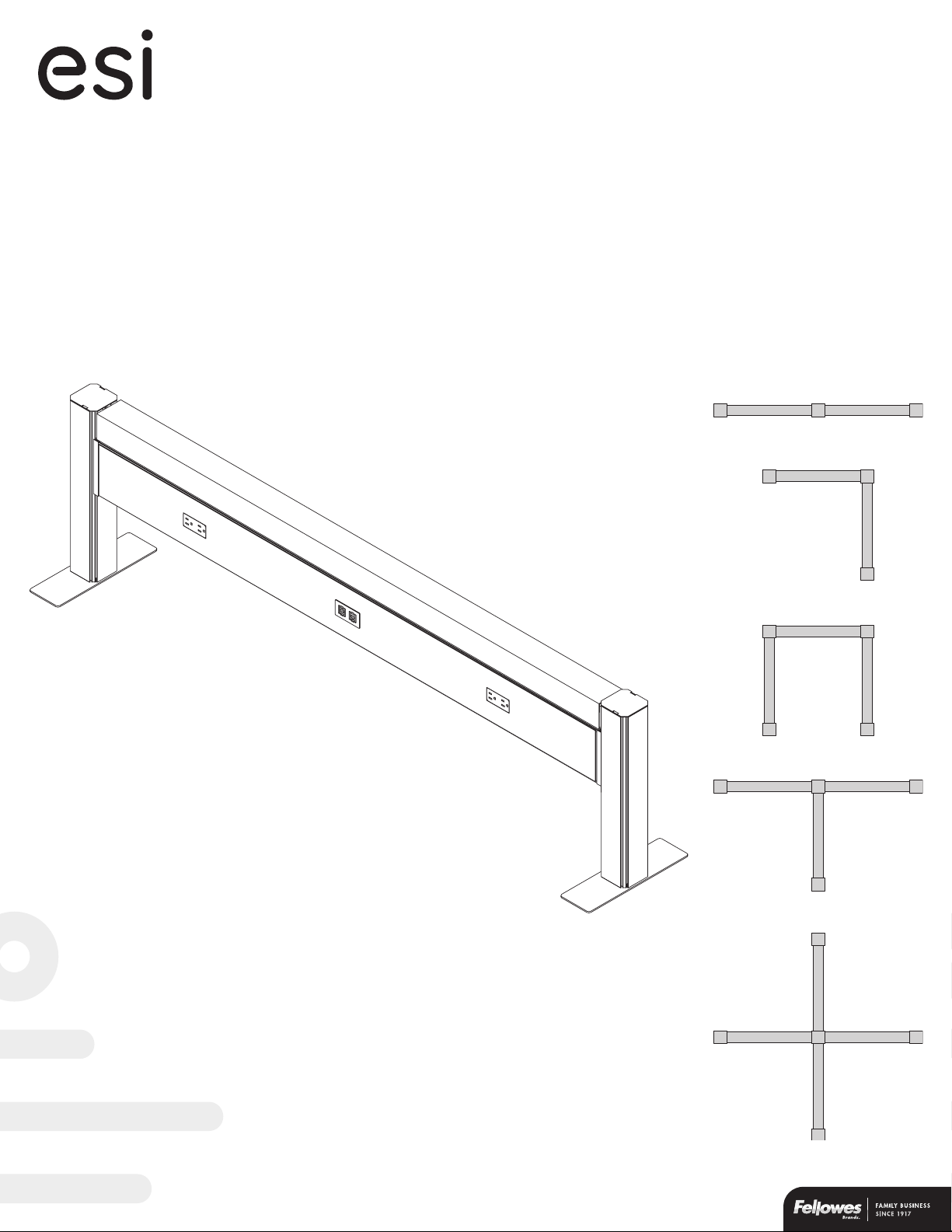
Railway™
model# RAIL-LINEAR
model# RAIL-90°
model# RAIL-BULLPEN
model# RAIL-3WAY
model# RAIL-4WAY
data and power solution
linear
3-way
4-way
90°
bullpen

Page 2
Please review these instructions before beginning the installation. Use the illustrations below and the table on the next page to check that the all
components needed for your installation were provided with your order. Do not discard the packaging until the product works to your satisfaction.
Components
Tools required
• Phillips screwdriver
• Power drill with Phillips #2 and #3 bits
Safety instructions/warning
• Only a licensed electrician should connect the power feed to building power.
• Connect the power feed to the unit before connecting it to building power.
Railway™Components and tools
rail assembly
36", 48", 60", or 72"
top data cover
36", 48", 60", or 72"
voice/data plate
voice/data
adapter kit
cover plate
jumper cable
22"
power feed
receptacle
rail posts
post feet
post cap
rail connectors
foot screws
mounting bracket
mounting bracket
screws
end post
(1 cutout)
180° post
(2 cutouts)
full
foot
#12-24x½"
Phillips #3 flat head
#8x½" self-tapping
Phillips #2 flange head
half
foot
90° post
(2 cutouts)
3-way post
(3 cutouts)
4-way post
(4 cutouts)
Page 3
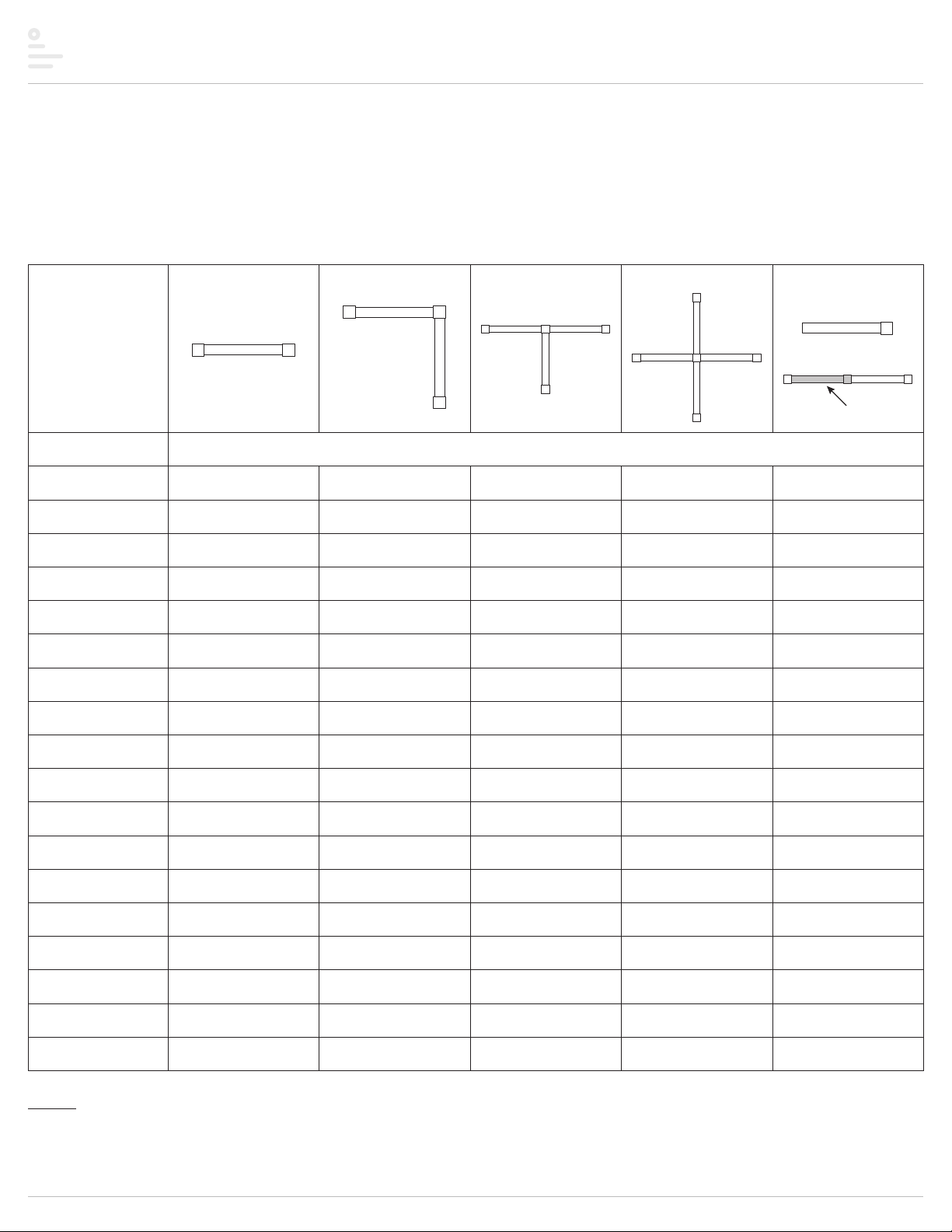
Railway™ Componentquantitiesbyconguration
The table below can be used to verify the quantities of each component provided with your order. The minimum number of rails is shown for each
configuration. Additional rails may be added to any of the configurations. Use the “additional rail(s)” column to calculate the number of added components
per additional rail. Bullpen configurations are configured as a 90degree plus an additional rail with a 90degree post instead of a 180degree. Be sure to
read the important notes under the table for further details related to the configurations.
Notes
• *The half foot is used when the unit will be positioned against a wall. Otherwise, the full foot is used.
• Power outlets and voice/data ports can be on one side of the rail (single run) or both sides (double run).
• Cover plates are installed when electrical receptacles or voice/data plates are not used.
conguration
linear 90° 3-way 4-way additional rail
(
s
)
item quantity
rail 1 2 3 4 1 per added rail
rail cover 1 2 3 4 1 per added rail
end post 2 2 3 4 —
180° post — — — — 1 per added rail
(rail added in-line)
90° post — 1 — — —
3-way post — — 1 — —
4-way post — — — 1 —
full or half foot* 2 3 4 5 1 per added rail
foot screws 812 16 20 4 per added rail
mounting bracket 2 4 6 8 2 per added rail
mounting bracket
screws 612 18 24 6 per added rail
rail connectors 4 8 12 16 4 per added rail
post cap 2 3 4 5 1 per added rail
receptacle 2 (single run)
4 (double run)
4 (single run)
8 (double run)
6 (single run)
12 (double run)
8 (single run)
16 (double run)
2 or 4 per added rail
(match adjacent rail)
voice/data plate 1 (single run)
2 (double run)
2 (single run)
4 (double run)
3 (single run)
6 (double run)
4 (single run)
8 (double run)
1 or 2 per added rail
(match adjacent rail)
voice/data adapter kit 1 2 3 4 1 per added rail
jumper cable — 1 2 3 1 per added rail
power feed 1111—
linear example:
added rail

Page 4
mounting
bracket
position
rail width
apart
Railway™Assembly
The following procedures are for a single rail two-post unit. These basic procedures apply to any Railway configuration. Contact Customer Service if you
have any questions at: 800.833.3746
Step 1: attach feet to base of posts
• Use four Phillips flat head screws per foot.
• Install the full foot or half foot perpendicular to the direction of the rail.
• Use the half foot when the posts will be positioned 4" or less from the wall or baseboard.
Step 2: hook mounting brackets to posts
• Stand the post assemblies upright, with the cutouts facing each other.
• Position the posts rail width apart.
• Hook the mounting brackets to the bottom of the cutouts.
#12-24x½"
full foot
half foot
half foot
4" or less
wall

Page 5
Step 3: attach rail to posts
• Place the rail onto the mounting brackets.
• Secure the rails to the post using the rail connectors, as shown below.
• Fasten each mounting bracket to the post and rail using three #8 self-tapping
Phillips flange head screws.
— Screw the bracket to the post with a screw through the hole in the tab.
— Screw the bracket to the rail with two screws through the bottom flange.
Step 4: remove rail assembly side cover(s)
• Lift the side cover from the rail and pull it out.
• If this is a double-run Railway (power outlets on both sides of rail),
remove the side cover from both sides.
Railway™Assembly
fasten mounting brackets
to post and rail
secure rail with
rail connectors
place rail on
mounting brackets
#8x½"
top of
connector
3
2
1
rail assembly
side cover
rail
Page 6
Railway™Assembly
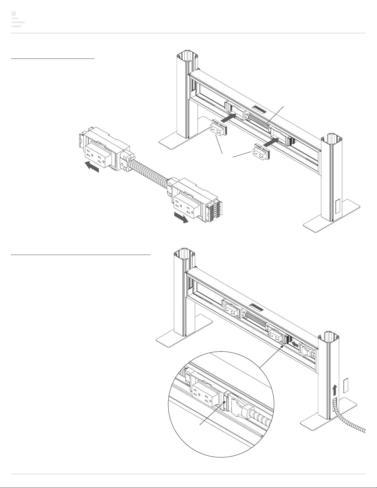
Step 5: install receptacles
• Insert the electrical receptacles into the power block.
• Then secure each receptacle into the power block connectors by pushing
the receptacles away from middle of the rail assembly toward the posts.
IMPORTANT: Check that the receptacles are securely connected to
the power block by sliding them back and forth.
Step 6: connect power feed to power block
• Remove the plastic cover from the base of the end post.
• Route the power feed up through the post and into the rail assembly.
• Insert the connector on the power feed into the power block.
• Coil the remaining power feed for safety.
IMPORTANT: Check that the power feed is securely connected
to the power block.
NOTE: The power feed may be connected to the building’s power
through the floor, wall, or ceiling.
power block
insert
receptacles
secure receptacles into
power block connectors
plastic
cover
connect
securely power feed
Page 7
Railway™Assembly
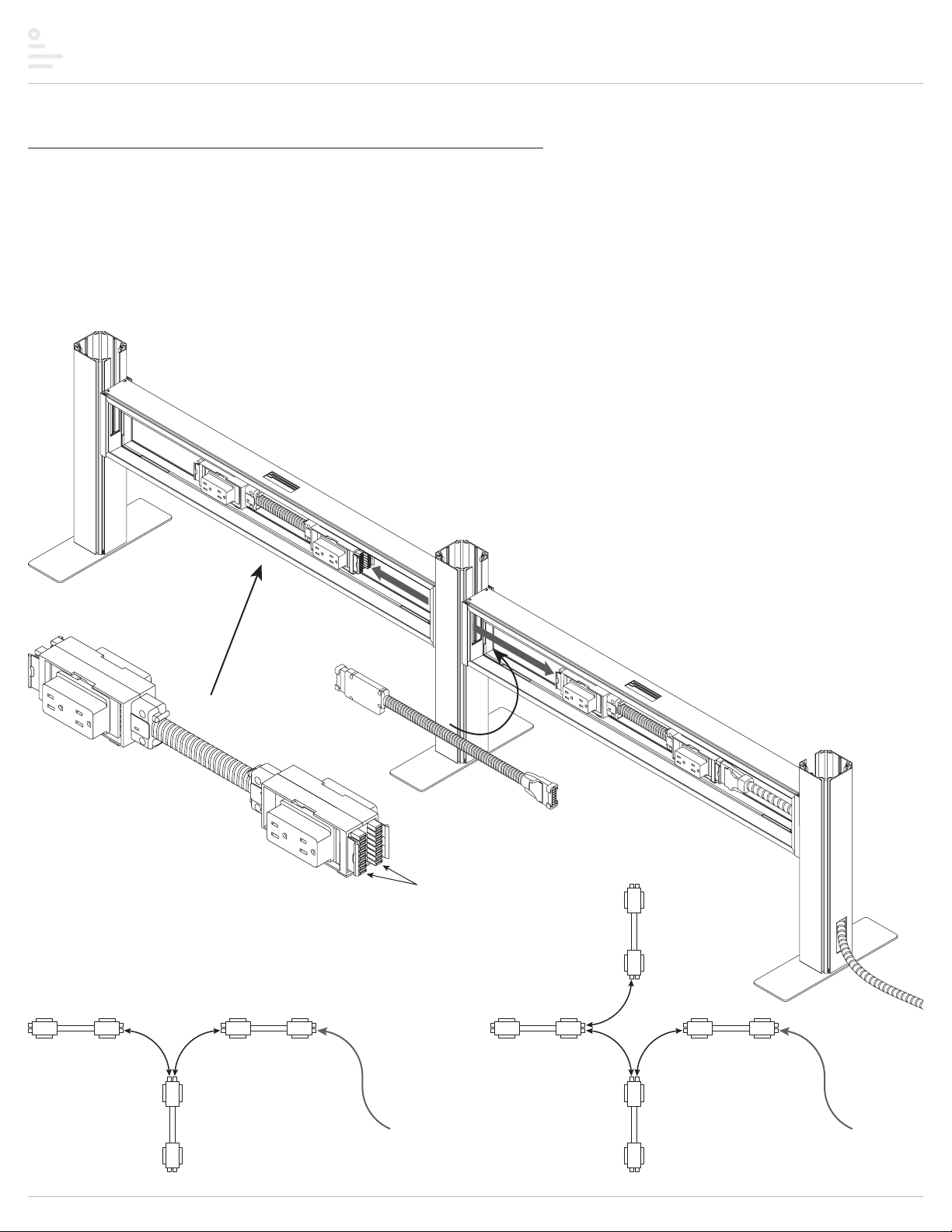
Step 7: connect power blocks with jumper cable(s) if necessary
One or more jumper cables are used to connect power blocks in two or more rail assemblies. Skip this step if your unit has only one rail assembly.
• Run the jumper cable through the openings in the rail ends and post.
• Insert the connectors on the jumper cable onto the power block in each rail assembly.
• With 3-way configurations, two jumper cables are used. With 4-way configurations, three jumper cables are used.
— Each end of the power block can accommodate two jumper cable connections.
— Refer to the illustrations at the bottom of the page to see how the jumper cables are routed for 3-way and 4-way configurations.
IMPORTANT: Check that each end of the jumper cable is securely connected to the power block.
accommodates two
jumper cable connections
power block
power feed
jumper
cables
jumper
cables
3-way routing 4-way routing
power feed
jumper
cable

Page 8
Step 8: route voice and/or data wires
Skip this step if voice/data wires will not be used with the unit.
• If routing through the base of an end post, remove the plastic cover at the
base of the post.
• Route the wires up through the post and out the slotted opening above
the rail.
• Route the wires across the top of the rail assembly and down through
the center opening.
• The wires may be routed in other appropriate ways depending
on installation type and installer preference, as long as the
voice/data jacks exit the center of the rail assembly, as shown.
Step 9: reinstall rail assembly side cover(s)
• Reverse the procedure described in step 4.
• Pull the jacks out through the center hole in the side cover before
securing the cover in place.
Railway™Assembly
voice/data
wires
rail assembly
side cover
jacks
rail

Page 9
Railway™Assembly
Step 10: install voice/data plate(s)
Skip this step if voice/data wires will not be used with the unit;
instead, install a cover plate over the opening (see step 11).
• Using the appropriate adapters in the voice/data adapter kit, attach
the jacks to the voice/data plate.
• Insert the voice/data plate into the center opening of the side cover
and push it securely in place.
Step 11: install cover plate(s) if necessary
• Install cover plates into any unused openings in the side covers.
— In the example shown, the Railway is “single run,” with power on only one side of the rail assembly.
— The three openings on the other side of the rail assembly should be covered.
• Push the cover plates into the side cover until they snap into place.
voice/data
plate
voice/data
adapter kit
push plate into
side cover
push plates into
side cover
Page 10
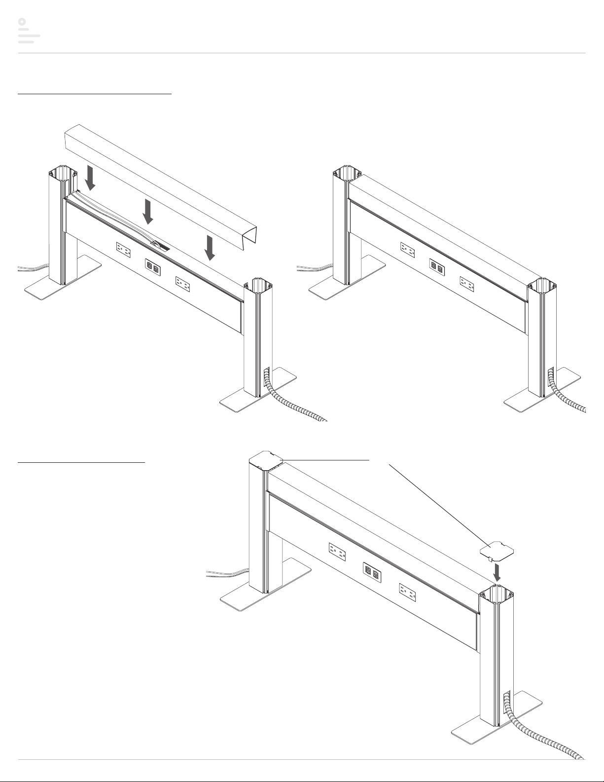
Railway™Assembly
Step 12: install top data cover
• Snap the top data cover onto the top of the rail assembly to conceal any wiring on the top of the rail and to provide a finished appearance.
Step 13: install post caps
• Place post caps on the top of each end post as shown.
post caps
This manual suits for next models
4
Table of contents
Other ESI Desktop manuals


