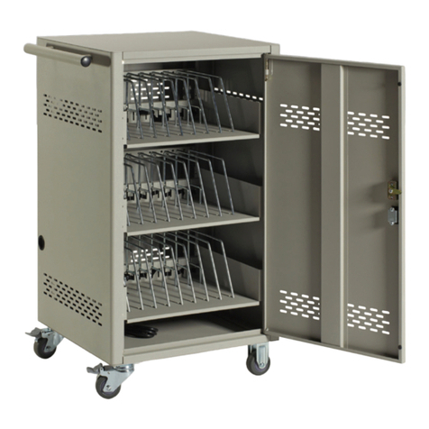
Esoltech FerroAmp PSM 10 Series User manual

PSM 10/12/15 Series
Installation manual
Ver.1.02 Oct. 2019
Esoltech AB, the battery
company

ii
TABLE OF CONTENTS
Warning.............................................................3
1. List of components.....................................4
2. Cabinet Assembly......................................6
2.1 Wall mounting:......................................7
2.2 Removing the side panels....................8
2.3 Adjusting the feet..................................9
2.4 Cable for LED panel ...........................10
3. Battery and Controller modules...............11
3.1 Touch Protection Covers....................12
3.2 Insert the battery modules..................14
3.3 Cable Installation ................................16
4. ESO module.............................................20
4.1 ESO assembly....................................20
4.2 Insert the ESO ....................................22
4.3 Cable installation.................................22
5. External cable..........................................24
5.1 DC-Link cable .....................................25
5.2 AC cable..............................................27
5.3 Cable gland.........................................28
6. Final Check and Finishing up..................29
6.1 Jumper bricks......................................29
6.2 Finishing up.........................................30
7. More information......................................32
7.1 Trouble shooting.................................32
7.2 Datasheet............................................34

PSM 10/12/15 Series Installation manual
Esoltech AB, the battery company
May 1, 2019 3
WARNING
•Read through the instruction manual before installation.
•Electrical installation shall be performed by an authorized electrician in accordance with
electrical standards and safety precautions
•Some component may need to be assembled before electrical installation.
•Do not open the enclosure of the electrical components. Warranty is void if the products
has been modified.
•Plug in the jumper brick (battery modules) only when the system is ready to power up.
The FerroAmp PSM 10/12/15 series high performance energy storage system is designed to be
installed and operated together with the EnergyHub system with the patented Adaptive Current
Equalization (ACE) technology.
FerroAmp Ferroamp Elektronik AB is a research-driven platform company that builds smart integrated energy
system for home and industry. The FerroAmp ACE technology is patented under PCT WO2012050501 (A1).
SES SunwodaEnergy Solution Co., Ltd is a professional energy storage solution provider with 20 years’ know-
how in battery industry. SES is a subsidiary of the listed Sunwoda Electronic Co., Ltd (SZ 300207) established
in 1997. SES is a manufacture powerhouse with it headquarter in Shenzhen, China.
ESOL ESOLtech AB, the battery company, is based in Stockholm. A company of doer brings knowledge into
reality.

PSM 10/12/15 Series Installation manual
Esoltech AB, the battery company
May 1, 2019 4
1. LIST OF COMPONENTS
The PSM 10/12/15 series high performance energy storage system comes with the following
components:
•Cabinet
•Battery modules
•Battery controller modules
•Energy Storage Optimizer (ESO)
•Accessories box
Knowing your system components:
Battery module
4 pcs (PSM10)
5 pcs (PSM12)
6 pcs (PSM15)
Battery controller module
1 pcs
Energy storage optimizer
1 pcs (6kW, PSM10)
2 pcs (12kW, PSM12/15)
The Cabinet
see picture on the index page
The Accessories box
see the list of accessories

PSM 10/12/15 Series Installation manual
Esoltech AB, the battery company
May 1, 2019 5
List of accessories:
Item no.
Description
quantity
note
1
Installation manual
1
This manual
2
Battery Module Comm. Cable
7
3
Battery Module Power cable
7
4
Battery Module Jumper Brick
6
5
Battery Module Mounting Bolts
18
M5
6
Wall mounting bolts
2
7
Wall mounting assembly
1
8
Wall mounting assembly bolts
2
9
Power Cable ESO - Battery controller
2
10
Battery controller Power cable 230VAC
1
11
Comm. cable: from ESO to Battery controller
1
12
Grounding cable for ESO
1
13
ESO Adaptor
1
14
ESO Adaptor fixing bolts
6
M3
15
ESO front panel
1
16
ESO front panel fixing bolts
8
M2

PSM 10/12/15 Series Installation manual
Esoltech AB, the battery company
May 1, 2019 6
2. CABINET ASSEMBLY
The cabinet is pre-assembled. The PSM cabinet is designed to be installed and used indoor
only. Before installation, please make sure that:
•the ambient temperature is 0 –45 deg. (recommended 25 deg.);
•the relative humidity ranges 0-95%;
•there is enough space around the cabinet to enable a safe installation.
Note: the measurement in the diagram is not to the scale

PSM 10/12/15 Series Installation manual
Esoltech AB, the battery company
May 1, 2019 7
2.1 Wall mounting:
Clear the wall. Measure the distance from the floor to the spot on the wall where mounting
assembly shall be fixed.
•Figure A: The wall mounting assembly can be attached to 3 locations on the cabinet.
The cabinet is shipped with the assembly preinstalled at location 1.
•Figure B: Fix the wall mounting piece to the wall.
•Figure C: Move the cabinet to the wall and fasten the fixing bolts to make sure the
cabinet is secured.
Please refer to Section 2.3 for the adjustment of the feet.
zoom in
wall mountingassembly
B
C
A

PSM 10/12/15 Series Installation manual
Esoltech AB, the battery company
May 1, 2019 8
2.2 Removing the side panels
The cabinet has a symmetric design meaning that the panels on the left-hand-side are
identical and exchangeable to the ones on the right.
The diagram shows the upper side panels and one of the lower side panels are removed. Detach
the grounding cable for installation clearance. The following shows the details of removing the
grounding cables.

PSM 10/12/15 Series Installation manual
Esoltech AB, the battery company
May 1, 2019 9
2.3 Adjusting the feet
There are 4 adjustable feet and the sockets are accessible when removing the side panels.
Using the hex key (5mm) to adjust the height of the feet.

PSM 10/12/15 Series Installation manual
Esoltech AB, the battery company
May 1, 2019 10
2.4 Cable for LED panel
Connecting the LED cable to the LED connector socket inside the cabinet as indicated below:
There is only one direction the cable can be inserted firmly. The following picture shows finished
LED cable connection. The other end of the cable is to be connected to the battery controller
module (See also Section 3.2).
LED Cable
(to the LED panel)
(to battery controller module)

PSM 10/12/15 Series Installation manual
Esoltech AB, the battery company
May 1, 2019 11
3. BATTERY AND CONTROLLER MODULES
Both the battery module and the battery controller box are shipped with protection covers
preinstalled.
Battery module:
Battery controller box:
The PSM system is shipped with one battery controller module and 4 - 6 battery modules
depending on system configuration.
Make sure to remove the preinstalled protection cover before installation.
cover
cover 2cover 3
Transparent piece
(click-on)
Black piece
(screw-fixed)
Touch Protection Cover
(black)

PSM 10/12/15 Series Installation manual
Esoltech AB, the battery company
May 1, 2019 12
3.1 Touch Protection Covers
For battery module:
The battery module with the protection covers removed:
cover piece2
cover piece1
Transparent click-on piece
Black screw-fixed piece

PSM 10/12/15 Series Installation manual
Esoltech AB, the battery company
May 1, 2019 13
For the battery controller module:
The battery controller module with the protection covers removed.
cover piece1
cover piece2
cover piece3
Transparent click-on piece
Transparent click-on piece
Black screw-fixed piece

PSM 10/12/15 Series Installation manual
Esoltech AB, the battery company
May 1, 2019 14
3.2 Insert the battery modules
The battery shall be inserted one by one from the bottom of the cabinet.
Make sure all the bolts for the inserted module fastened before installing the next module.
Install the controller module after all the battery modules are done.
Pay special attention not to block the Cable for LED panel (Section 2.4) whose connection is
to be done in Section 3.3.

PSM 10/12/15 Series Installation manual
Esoltech AB, the battery company
May 1, 2019 15
The following is a side view of the system after insertion of the battery and controller modules.
Make sure all the bolts fastened before proceeding for safety installation.
Controller
Batt. 1
Batt. 2
Batt. 3
(Slot for ESO)
Batt. 6
Batt. 5
Batt. 4

PSM 10/12/15 Series Installation manual
Esoltech AB, the battery company
May 1, 2019 16
3.3 Cable Installation
3.3.1 Connection overview and the numbering of the cables (PSM15):
Batt. Power cable
Batt. comm. cable
Protectiveearth
label 1label 2
CON_BAT_NG BAT1_NG
B A T 1 _ P G BAT2_NG
B A T 2 _ P G BAT3_NG
B A T 3 _ P G BAT4_NG
B A T 4 _ P G BAT5_NG
B A T 5 _ P G BAT6_NG
B A T 6 _ P G CON_BAT_PG
CON_COM2 BAT1_COM1
BAT1_COM2 BAT2_COM1
BAT2_COM2 BAT3_COM1
BAT3_COM2 BAT4_COM1
BAT4_COM2 BAT5_COM1
BAT5_COM2 BAT6_COM1
BAT6_COM2 CON_COM1
C O N L E D C O N L E D
#
1
2
3
4
5
6
7
8
9
10
11
12
13
14
15

PSM 10/12/15 Series Installation manual
Esoltech AB, the battery company
May 1, 2019 17
Sort the cables according to the list above and
install the cables according to the numbering. As
indicated in the left-hand side figure:
•Connect the power cables (solid line)
•Connect then the communication cables
(dashed line)
Install the battery module protection covers
(Section 3.1) back. After the installation the system
looks like the figure on right-hand side.

PSM 10/12/15 Series Installation manual
Esoltech AB, the battery company
May 1, 2019 18
3.3.2 Connection overview and the numbering of the cables (PSM10):
Batt. Comm.
Batt. Power
PE Connection (6mm)

PSM 10/12/15 Series Installation manual
Esoltech AB, the battery company
May 1, 2019 19
Zoomed in:

PSM 10/12/15 Series Installation manual
Esoltech AB, the battery company
May 1, 2019 20
4. ESO MODULE
Depending on the system configuration, one or more ESO modules are shipped alongside with
your PSM system. The ESO module is shipped in a cardboard package without pre-assembly.
Each ESO module resembles a rectangular metal box. Please skip to 4.2if ESO is shipped pre-
assembled.
4.1 ESO assembly
The following instruction applies to the two-ESO system with a nominal power of 12kW.
Lay the two ESO modules side by side on a flat surface. Make sure the second one (ESO2)
have the bottom metal enclosure facing upward as indicated in the picture below.
Note that the weld nuts are visible from the ESO bottom metal enclosure.
Install the ESO adaptor:
Other manuals for FerroAmp PSM 10 Series
1
This manual suits for next models
5
Table of contents
Other Esoltech Storage manuals
Popular Storage manuals by other brands

Iomega
Iomega DVR 34172 Specifications
OCZ
OCZ SATA III 2.5” installation manual

Samsung
Samsung Enterprise Capacity 3.5 HDD/Constellation ES installation guide

Actidata
Actidata actiDisk RDX user guide

Hewlett Packard Enterprise
Hewlett Packard Enterprise MSA 1040 user guide
Pylontech
Pylontech PowerCube-X1 Operation manual

