Espa Max series User manual

www.espa-pumps.co.uk

www.espa-pumps.co.uk
EN
PressureWave™/ Max™/ UltraMax™/ M-Inox™/ E-Wave™/ Challenger™/
C2-Lite CAD™/ FlowThru™/ All-Weather™/ HeatWave™/ SolarWave™/
ThermoWave™Series
CAUTION: To prevent personal injury, ensure all water
pressure is released from the pressure system prior to work
being performed. Ensure pumps are disconnected and / or
electrically isolated.
WARNING: It is strongly recommended that the system is
protected by a suitable pressure relief valve set at or below
the maximum tank pressure rating. Failure to install a relief
valve may result in tank explosion in the event of a system
malfunction or over pressurization, resulting in property
damage, serious personal injury or death.
WARNING: If the pressure tank leaks or shows signs of
corrosion or damage do not use it.
Installed on __________ by ________________
W
These instructions have been prepared to acquaint you with the
correct method of installing and operating your GWS pressure
tank. We urge you to study this document carefully and follow all
the need for further advice, you should contact the dealer from
PressureWave™, Max™, UltraMax™, M-Inox™, E-Wave™,
All-Weather™, Challenger™, C2-Lite CAD™, and
FlowThru™Series tanks are designed for use in well water or
potable water booster systems. Refer to Sec. 1 for installation
details.
HeatWave™and SolarWave™Series tanks are designed
for use in non-potable closed loop hydronic or solar water
heating systems. Refer to Sec. 2 for installation details.
ThermoWave™Series tanks are designed for use in open loop
potable water heating applications. PressureWave™, E-Wave™,
Challenger™and SuperFlow™Series may also be used in
open loop potable water heating applications. Refer to Sec. 2
for installation details.
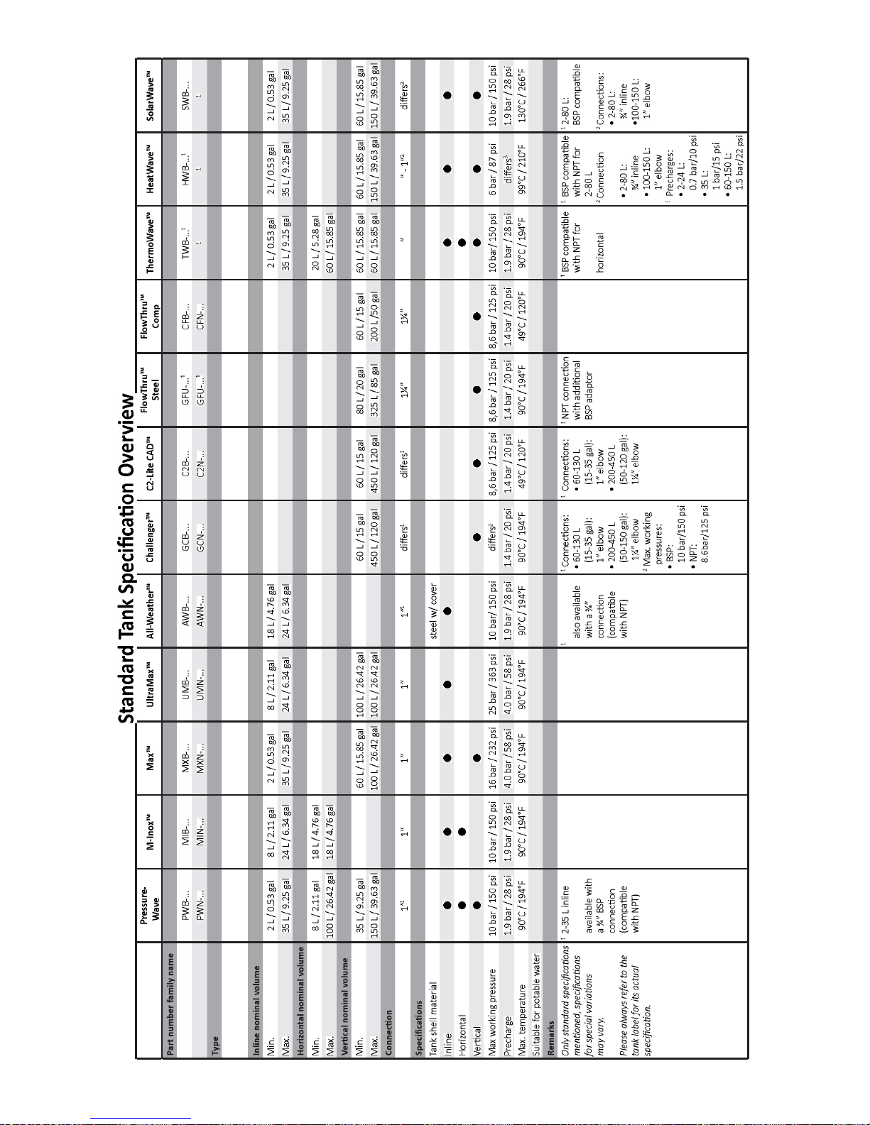
See tank data label for maximum working pressure and
maximum temperature.
Be sure to protect tank, piping and all system components
from freezing temperatures.
The manufacturer is not responsible for any water damage in
connection with this diaphragm pressure tank.
Installation
In order to ensure your tank provides its maximum service
life it should always be installed in a covered, dry position. The
tank should not be allowed to rub against any surrounding hard
surfaces, such as walls etc.
Install the tank at a suitable location to prevent water damage
due to leaks. The tank should always be located downstream
from the pump. If the tank is located at a lower elevation than
the demand then a check valve should be installed. If the tank is
installed remotely from the pump then install the pressure switch
near the tank.The tank should be installed as close as possible to
adverse effects of added friction loss and differences in elevation
between the tank and / or the water mains’and the pressure
switch, transducer or sensor.
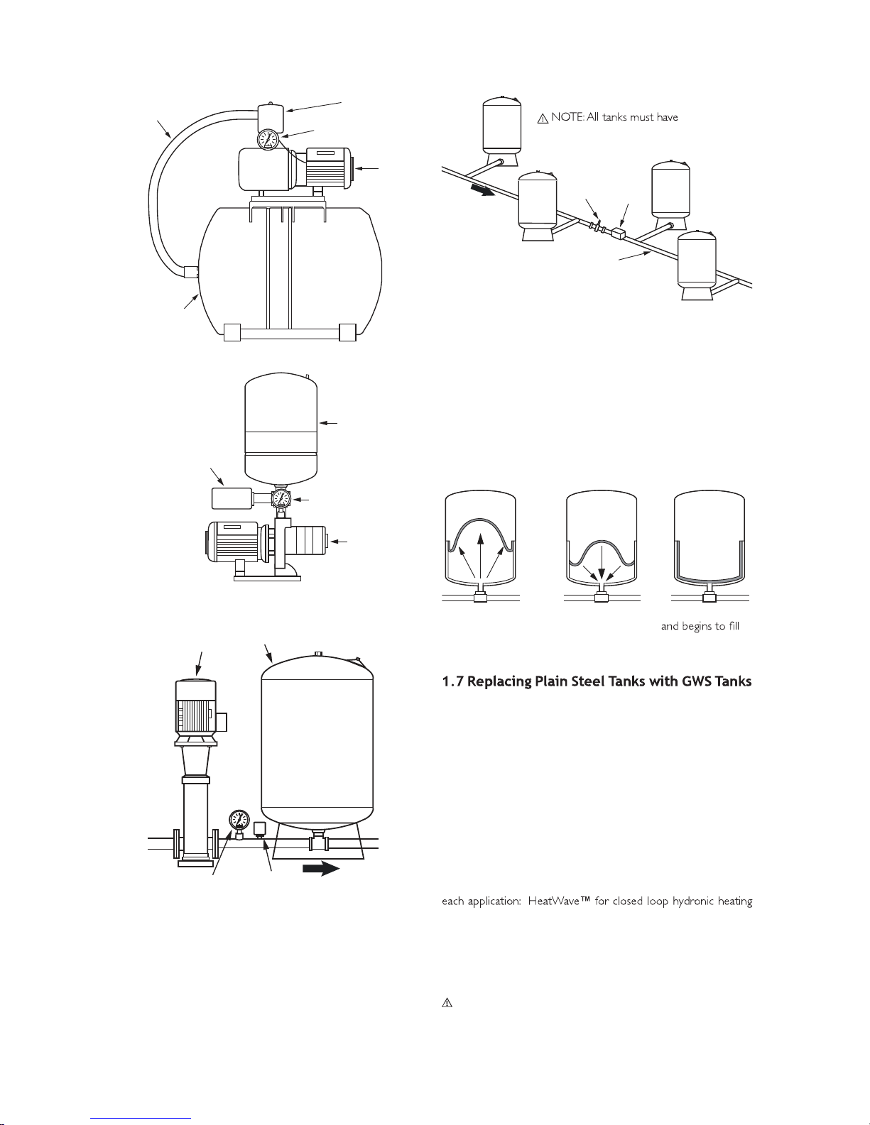
1.2 System Connection
1.
2. Level as necessary. All vertical and horizontal model tanks
in the vicinity the tank should be mounted on a resilient
mounting. Tanks with steel bases should be mounted using
supplied “L”brackets, while tanks with plastic bases should be
mounted through the holes in the base. For bases without
holes, holes should be drilled at four points equally distant
along the rim of the base and then mounted accordingly. Inline
tanks should be connected directly to the pump or to the
supply line using a “T”connection.
3. Connect the tank to the pump supply line with a short pipe to
eliminate unnecessary friction loss.
4. All piping should be in accordance with prevailing local codes
and standards.
5.
connections.
6. Tanks mounted on booster sets should be strapped down for
shipment.
1.3 Adjusting Precharge Pressure
Correct precharge is required for proper tank performance.
1. For tanks installed with a pressure switch controlled pump
with a differential pressure set up to 2 bar (30 psi), the
precharge should be set to 0.2 bar (2 psi) below the cut-in
pressure.
2. For tanks installed with a pump controlled by a pressure
switch with a pressure differential greater than 2 bar (30 psi),
electronic controls or variable speed controls, the precharge
should be set to 65% of the cut-out or maximum system
pressure.
3. For tanks installed on mains’pressure, the tank precharge
should be set equal to the mains’pressure. For mains’pressure
EN

www.espa-pumps.co.uk
EN
exceeding 6 bar (88 psi), a suitable pressure regulator should
be installed.
For correct operation, pressure tanks should be precharged as
follows:
1. Turn off the pump, disconnect the tank from the system and
completely drain all water inside the tank to avoid water
pressure affecting precharge readings.
2. Using a suitable pressure gauge, check the precharge pressure
of the tank.
3. Release or add air as necessary to adjust to the required
precharge pressure.
4. Replace protective air valve cap and seal with the air valve
label, if provided.This will enable you to determine if the valve
has been tampered with in case of future service calls.
5. After correctly setting the precharge, no regular air charge
checks are required.
Do not check air after installation.
CAUTION:
tank with air at ambient temperature only!
If the tank is to be precharged over 4 bar (58 psi):
1. Adjust the precharge of the tank to 4 bar (58 psi).
2. Install the tank into the system.
3. Fill the system with water to equalise the system and
precharge pressure at 4 bar (58 psi).
4. Increase precharge pressure in maximum 3 bar (44 psi)
steps and afterwards adjust the system pressure to the new
5. Repeat steps 3 and 4 until the required precharge is reached.
Emptying a tank that has a precharge over 4 bar (58 psi):
1. Make sure there is some water in the tank.
2. Isolate the tank from the system (close isolation valve).
3. Make sure no additional water can get into the tank (shut off
the pump and / or any water supply).
4. Release air from tank until 3 bar (44 psi) tank / air pressure
is remaining.
5. Open a drain valve and afterwards the isolation valve to drain
the tank.
CAUTION: Make sure that the system pressure is never
lower than 4 bar (58 psi) below precharge. If system pressure
needs to be lowered, the tank should be isolated or emptied
as previously described.
1.4 Typical Installations
Fig. 1.4-1 Tank Installation with Accessories
Tranducer
Flow Sensor
Pressure Switch
Pressure Gauge
Relief Valve
Water Flow
Tank
This is a diaphragm type pressure tank for use on a well water
or booster system.The system must be protected by a suitable
relief valve.
FlowThru™Series tanks should only be used in Variable
Speed Drive or Variable Frequency Drive controlled pumping
systems.
Fig. 1.4-2 With Convertible Jet Pump
Tank
Relief Valve
Drain
Pump
Water Flow
Fig. 1.4-3 With Submersible Pump
Relief Valve
Tank
To System
Water Flow
Submersible Pump
From
Pump

www.espa-pumps.co.uk
EN
Tank
Fig. 1.4-4 Booster Pump w/ Horizontal Tank
Pressure Switch
Pressure Gauge
Flexible
Connector
Pump
Fig. 1.4-5 Booster Pump w/ Inline Tank
Pressure
Switch
Pressure Gauge
Tank
Pump
Transducer
Pressure Gauge Water Flow
Tank
Pump
Fig. 1.4-6 Booster Pump w/ Tank
1.5 Multiple Tank Installation
All tanks must have the same precharge for the system to function
properly.Tanks should be installed on a header to ensure all tanks
receive equal and balanced pressure. Adjust each tank precharge
as detailed in section 1.3.The system pressure switch or control
should be centrally located (see Fig 1.5) in order for the tanks to
function properly.
Fig. 1.5 Multi-tank Installation
equal precharge
Relief
Valve Pressure
Switch
Header to be sized
for maximum velocity of
1.8m/sec (6ft/sec)
WaterFlow
1.6 Pump Run Control Operating Principles
Without a pressure tank, a water system’s pump would cycle
(turn on) every time there was a demand for water.This frequent
and potentially short cycling would shorten the life of the pump.
Pressure tanks are designed to store water when the pump is
running and then deliver pressurized water back to the system
when the pump is shut off (Fig 1.6). A properly sized tank will
store at least one liter of water for every liter per minute (LPM) of
pump capacity. This allows for fewer pump starts and longer run
times which should maximize the life of the pump.
1. Before drawdown 2. During
drawdown
3. Pump comes on
the tank
Fig. 1.6
GWS recommends that defective plain steel tanks are replaced
with GWS tanks. It is strongly recommended that a relief valve is
installed at the GWS tank connection. Also be sure to plug the
air port on a jet pump, as air is no longer required to be supplied
to the tank.
2. Thermal Expansion Tank Installation
Thermal expansion tanks are designed to accommodate the
natural expansion of water as it is heated. Thermal expansion
tanks may be used in several different applications including
closed loop hydronic heating systems, direct and indirect solar
heating systems, and open loop potable water heating systems.
GWS has developed three different series of tanks to be used for
systems, SolarWave™for indirect closed loop solar heating
systems, and ThermoWave™for direct solar heating and open
loop potable water heating systems. For high volume thermal
expansion applications Challenger™and SuperFlow™Series
tanks may be used.
CAUTION: Check tank data label for maximum operating
pressure and temperature prior to installing.

www.espa-pumps.co.uk
EN
CAUTION: Additives (such as glycol) can affect the thermal
expansion and expansion tank operation. Check with your
WARNING: It is strongly recommended that any heating
system is protected by a suitable pressure relief valve set
at or below the maximum tank pressure rating. Failure to
install a relief valve may result in tank explosion in the event
of a system malfunction or over pressurization, resulting in
property damage, serious personal injury or death.
2.1 Precharge
Using a suitable pressure gauge, check the tank precharge
pressure prior to installation. Refer to the tank data label for
factory precharge pressure. HeatWave™tanks in closed loop
ThermoWave™tanks in open loop heating storage systems
should be precharged to mains’pressure. For SolarWave™tanks
in closed loop solar systems precharge should be set at minimum
by the tank air valve accordingly. Make sure the tank is completely
drained of water and there is no system pressure affecting the
precharge pressure reading when adjusting tank precharge.
2.2 Thermal Expansion Tank Location
As tanks, pipes and connections can leak even when installed
correctly; make sure to install the tank at a location where any
leak will not cause water damage. The thermal expansion tank
should be installed on the cold or supply side of any heating
system. The tank should be installed indoors and protected from
freezing temperatures.
2.3 System Connection
Fig. 2.3-1 Fig. 2.3-2
Hot
Relief
Valve
Relief
Valve
BackFlow
Preventer
or Check
Valve
BackFlow
Preventer
or Check
Valve
Vertical
Tank
w/ Base
Inline
Tank
ColdHot Cold
Thermal expansion inline tanks are designed to be supported by
system piping and should be connected to the system piping using
a “T”connection (See Fig.2.3-1). Optional wall mounting brackets
are also available for increased support (check with your local
GWS dealer for more information). Vertical tanks with base are
designed to be self-supporting and should be connected to the
system with additional piping (See Fig. 2.3-2).
2.4 Solar Heating System Connections
Fig. 2.4
Hot
Cold
Pump
Pump
Solar Collector
Condenser
SolarWave
TM
Tank
SolarWave™tanks are intended for use in the solar liquid
loop of indirect thermal transfer systems and may be mounted
either on the suction or pressure side of the circulation pump.
If a condenser is employed to cool evaporated solar liquid it
must be in the location between the solar liquid loop and the
expansion tank. A relief valve should be employed and maximum
operating parameters must not be exceeded. If the temperature
of the solar system has the potential to rise above the evaporation
point of the solar liquid, a condenser chamber or coil is required
between the solar collector and the expansion tank (See Fig. 2.4).
2.5 Thermal Expansion Operating Principles
As water is heated it expands.A thermal expansion tank is used to
accommodate for this natural water expansion, which otherwise
may lead to increased system pressure and cause damage
expansion tank uses a diaphragm membrane sealed inside the
vessel to create a barrier between water and air chambers.The
air chamber acts as a cushion which compresses as heated water
expands.The thermal expansion tank absorbs the expanded water
volume and ensures constant system pressure is maintained. Using
a thermal expansion tank also conserves water and energy. This
lost due to venting from the relief valve during heating cycles.
3. Disposal
Check with local authorities for
proper disposal and recycling.

www.espa-pumps.co.uk
Global Water Solutions Ltd. (GWS) warrants its Challenger™, FlowThru™, C2-Lite CAD™, PressureWave™, M-Inox™, Max™,
UltraMax™and All-Weather™tanks against manufacturing defects in material and workmanship for a period of 5 years, SolarWave™,
ThermoWave™tanks for 3 years and HeatWave™tanks for a period of 2 years from the date of manufacture. Warranty applies to
Global Water Solutions products only when used for their intended purpose, and does not apply if a defect is due to improper use of
by the factory, the warranty is void.The warranty set forth in this paragraph is made expressly in lieu of all other warranties expressed,
delay in delivery, or any loss sustained by the buyer nor will GWS be liable for labor and expenses necessary to remove and reinstall
replacement product.
To obtain service under this warranty, the consumer must deliver alleged defective product, freight prepaid, to an authorized GWS
distributor or OEM partner. GWS will either issue credit or at its option, repair or replace defective product freight prepaid to the
distributor. GWS reserves the right to make changes in construction, which, in its judgment, constitutes a product improvement.
pressure relief valve as recommended in the installation manual.
PressureWave™/ Max™/ UltraMax™/ M-Inox™/ E-Wave™/ Challenger™/ C2-Lite CAD™
FlowThru™/ All-Weather™/ HeatWave™/ SolarWave™/ ThermoWave™Series
EN
Warranty

www.espa-pumps.co.uk
Declaration of Conformity
Declaração de Conformidade
Overensstemmelseserklæring
Déclaration de Conformité
Declaración de Conformidad
Vastaavuusvakuutus
In accordance with EU directive 97/23/EC
Pressure Vessels Types MT_ _ / ST_ _ / HT_ _ / PT _ _
Alexander Staudt
Technical Manager
Luxembourg, July 17 2013Global Water Solutions Ltd.
St. Helier –JE1 2TR
Jersey
The Channel Islands
DOC

www.espa-pumps.co.uk
Alexander Staudt
Technical Manager
Luxembourg, July17 2013Global Water Solutions Ltd.
St. Helier –JE1 2TR
Jersey
The Channel Islands
Declaration of Conformity
Declaração de Conformidade
Overensstemmelseserklæring
Déclaration de Conformité
Declaración de Conformidad
Vastaavuusvakuutus
In accordance with EU directive 97/23/EC
Pressure Vessels Types MUPA / MUPN / MUFA / CUPA / CUTA / CUFA
DOC

Acceptance Factor Overview
AF Overview
1
000
0 0
0
0
0
0
0
0
0
0
10
10 100 110
0 0
0
0
0
0
0
0
0
0
0
100
0
110
0 0
0
Maximalsystemdruck - Maximální tlak v systému - Pression max. de fonctionnement - Pres-
do sistema - Presiunea maxim de operare a sistemului - Presión máx de operación del sistema

™
BSP
NPT
Type family MTPA
MTPB
STPA
STPB
MTMA
MTMB
MTUA
MTUB PTPB MUPA
MUPN CUPA MUFA CUFA MTPA MTHT MTHH
Size ¾ ¾
steel SS steel steel steel composite steel composite steel steel steel
yes yes yes yes yes yes yes yes yes yes no no
tanks also
inline tanks
inline and
models sizes:
with NPT

Espa Pumps (UK) Ltd
15-16 Riverside Avenue West
Lawford, Manningtree Essex CO11 1UN
Tel: (01206) 391291 / Fax: (01206) 391239
sales@espa.co.uk / www.espa-pumps.co.uk
This manual suits for next models
10