ESPRIT ESPR.BODYB User manual

INSTALLER:
Leave this manual with the appliance.
CONSUMER:
Retain this manual for future reference.
ESPRIT250418-56 100000393-50
This appliance is suitable for installation in a
bedroom or bed sitting room.
ESPRIT
INSTALLATION AND
OPERATING INSTRUCTIONS
MODEL: ESPR.BODYB
SERIES: B
ESPRIT ZERO CLEARANCE
BALANCED FLUE
FIREPLACE
WARNING: If the information in these
instructions are not followed exactly, a fire
or explosion may result causing property
damage, personal injury or loss of life.
FOR YOUR SAFETY
Installation and service must be
performed by a qualified installer, service
agency or the gas supplier
WHAT TO DO IF YOU SMELL GAS
• Do not try to light any appliance.
• Do not touch any electrical Switch.
• Do not use any phone in your building.
• Immediately call your gas supplier
• from a neighbour’s phone. Follow the
gas supplier’s instructions.
• If you cannot reach your gas supplier
call the fire department.
Do not store or use petrol or other
flammable vapours and liquids in the
vicinity of this or any other appliance.
This appliance is only for use with the type
of gas indicated on the rating plate. This
appliance is not convertible for use with
other gases unless a certified kit is used.
SERIAL #
Gas Safety
Cered
AS/NZS 5263.1.3
SAI-400322
This appliance is certified for
use in Australia with Natural
Gas and Liquid Propane Gas.
This appliance is certified
for use in New Zealand with
Natural Gas only.

2
100000393-50 ESPRIT
250418-56
Caution ................................................................... 3
Safety ......................................................................4
Warnings and Cautions ...........................................5
First Fire ...................................................................7
Operating Instructions .............................................7
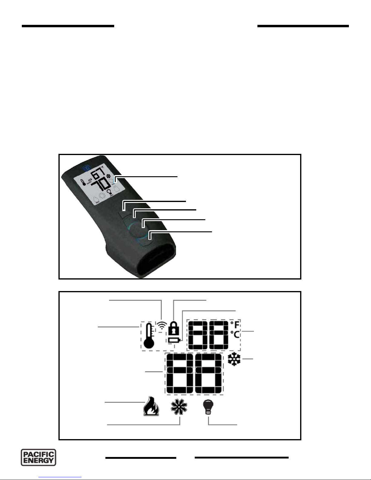
Remote Control Operation ..................................... 8
System Description .............................................. 8
Transmitter (Remote Control with LCD Display) . 8
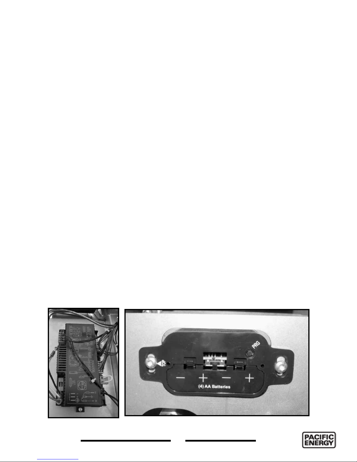
IFC Module........................................................... 9
Operating Procedure ............................................ 9
Initializing the System for the rst time ................ 9
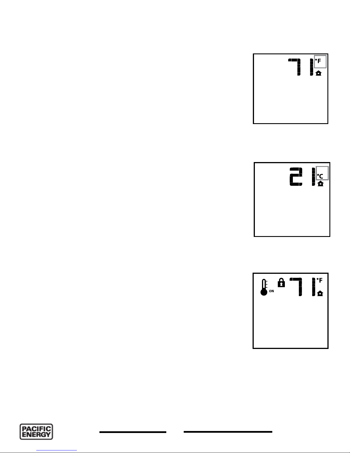
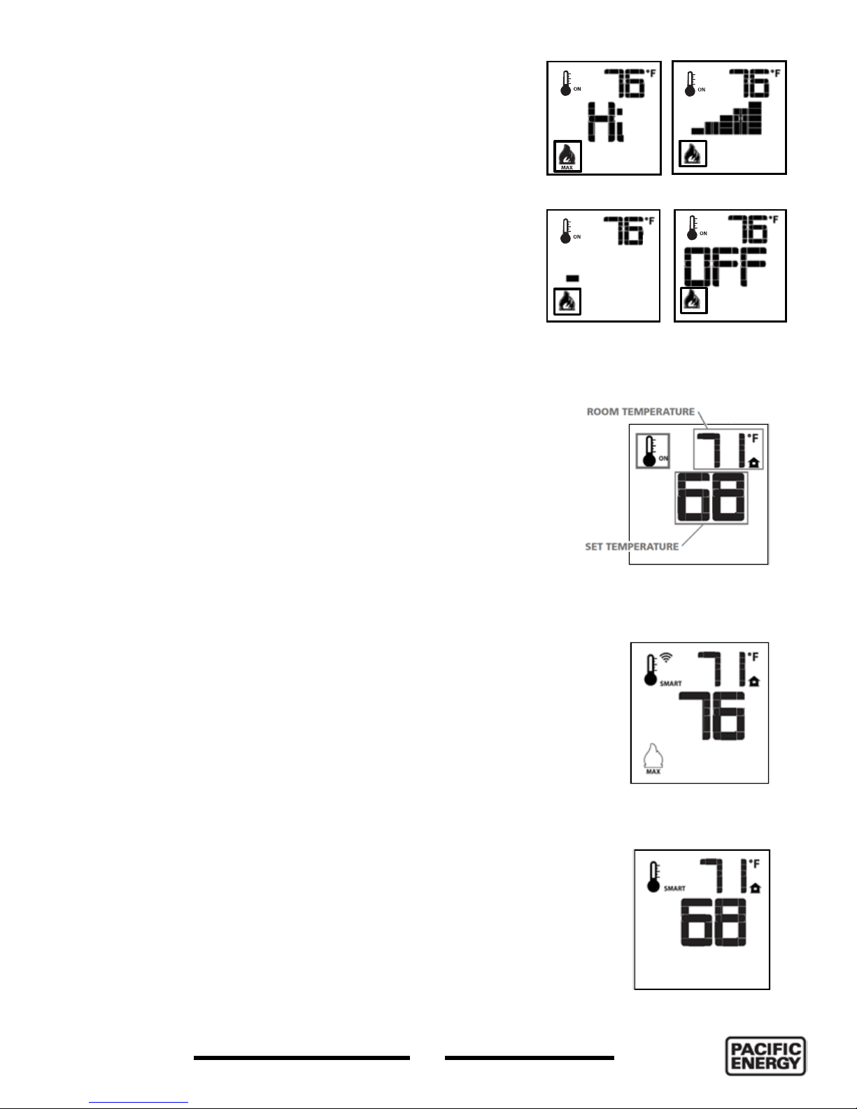
Temperature indication Display .......................... 10
Turn on the Fireplace .......................................... 10
Turn off the Fireplace .......................................... 10
Manual Bypass of the Remote System.............. 10
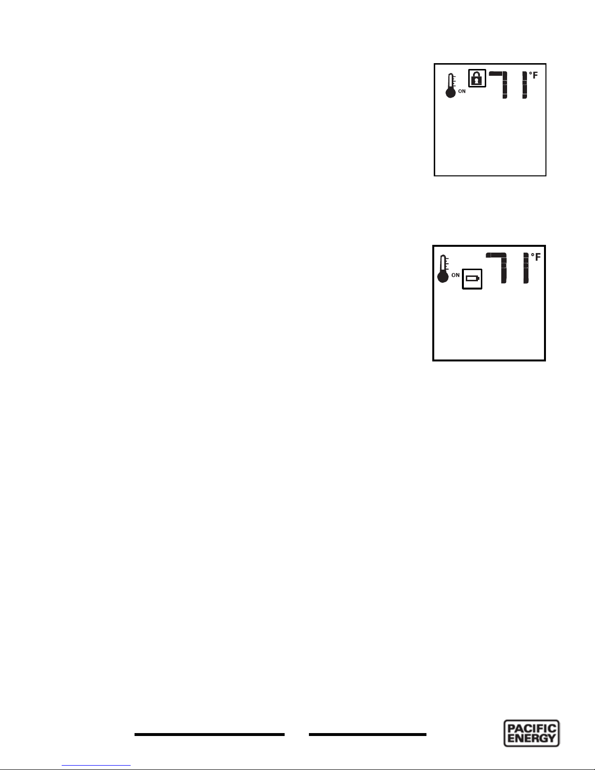
Key Lock............................................................. 10
Remote Flame Control .......................................11
Room Thermostat (Transmitter Operation)..........11
Smart Thermostat (Transmitter Operation) .........11
Comfort Fan Speed Control ...............................12
Continuous Pilot/Intermittent Pilot
(CPI/IPI) selection ................................................12
Remote dimmer control (Light)............................12
Key Lock............................................................. 13
Low Battery Power Detection ............................ 13
Transmitter .......................................................... 13
Receiver.............................................................. 13
Note regarding Power Failure............................. 13
Lighting Instructions ..............................................14
Installing the Esprit ................................................15
Installation Checklist ...........................................15
Esprit Dimensions ................................................ 16
Locating the Fireplace ...........................................17
Non combustible Facing Material Installation ...... 18
Clearances to Combustibles ................................ 19
Minimum Clearance to Combustible Materials .. 19
Mantel Clearances ................................................ 20
Framing and Finishing ...........................................21
Floor Installation ..................................................21
Mounting Brackets ..............................................21
Vent Terminal Minimum Clearances ......................24
Venting Chart .........................................................25
Venting ..........................................................................
.................26
Installing Standoffs ................................................ 26
Maneuver the Esprit into place ............................. 26
Install Venting ....................................................... 26
Gas Connection .....................................................27
Gas connection ..................................................27
Gas Suppy ............................................................ 28
Gas Pressure Check ............................................. 28
Gas Pressure Testing Procedure .......................... 29
Intake Air Damper Installation .............................. 30
Glass Burner Tray Installation ................................31
Rock Set Installation ..............................................34
Log Set Installation ................................................35
Kit Contents.........................................................35
Log set installation ............................................. 36
Door Removal / Installation .................................. 39
Surround Installation Instructions ......................... 40
LED Light Replacement .........................................41
Pilot Assembly Replacement ................................42
Accessing the Gas Injector ...................................44
Blower Fan Replacement ......................................45
Propane Conversion ..............................................47
Maintenance ......................................................... 48
Glass Door ......................................................... 48
Annual Inspection .............................................. 48
Periodically ......................................................... 48
Replacement Parts ............................................... 49
Wiring Diagram ..................................................... 50
Notes .....................................................................51
Table of Contents
AS/NZS 5263.0:2017 contains the requirements and methods of compliance for the “design,
installation and commissioning of gas installations that are associated with the use or
intended use of fuel gases such as natural gas, LP gas or biogas.”
LISTINGS AND CODE APPROVALS
These gas appliances have been tested in accordance with AS/NZS 5263.0:2017 and have
been certified by the Australian Gas Association for installation and operation as described in
these Installation and Operating Instructions. Must be installed as per AS/NZS 5601. Your unit
should be serviced annually by an authorized service person.

3
250418-56 100000393-50
ESPRIT
This fireplace is equipped with a micro mesh safety screen for your protection and
must be installed with the unit. Removal of the safety screen will cause the fireplace
to become a burn and fire hazard.
FOR YOUR SAFETY - Do not install or operate your Pacic Energy replace without rst reading
and understanding this manual. Any installation or operational deviation from the following
instructions voids the Pacic Energy Warranty and may prove hazardous.
This appliance and its individual shut off valve must be disconnected from gas supply piping system
during any pressure testing of that system at test pressures in excess of 3.5 kPa.
This appliance must be isolated from the gas supply piping system by closing its individual manual
shut off valve during any pressure testing of the gas supply piping system at test pressures equal to
or less than 3.5 kPa.
Do not use the replace if any part has been under water. Immediately call a qualied service
technician to inspect the replace and to replace any part of the control system and any gas control
which has been under water.
Caution

4
100000393-50 ESPRIT
250418-56
Safety
• A barrier designed to reduce the risk of burns from the hot viewing glass is provided with the
Surround Kit component and shall be installed.
• If the barrier becomes damaged, the barrier shall be replaced with the manufacturers barrier
for this appliance.
Any grill, panel or door removed for servicing the unit must be replaced prior to operating.
• It is our policy that no responsibility is assumed by the Company or by any of its employees or
representatives for any damages caused by an inoperable, inadequate, or unsafe condition which
is the result, either directly or indirectly, of any improper operation or installation procedures.
WHAT TO DO IF YOU SMELL GAS
• Do not try to light any appliance.
• Do not touch any electrical Switch.
• Do not use any phone in your building.
• Immediately call your gas supplier from a neighbor’s phone. Follow the gas supplier’s instructions.
• If you cannot reach your gas supplier call the re department.
• Installation and service must be performed by a qualied installer, service agency or the gas
supplier.

5
250418-56 100000393-50
ESPRIT
Warnings and Cautions
DUE TO HIGH TEMPERATURES, THIS GAS APPLIANCE SHOULD BE LOCATED OUT OF
TRAFFIC AND AWAY FROM FURNITURE AND DRAPERIES.
WARNING
SHOCK HAZARD. CAN CAUSE SEVERE INJURY OR DEATH. THIS DEVICE IS POWERED
BY LINE VOLTAGE. DO NOT TRY TO REPAIR THIS DEVICE. IN NO WAY IS THE
ENCLOSURE TO BE TAMPERED WITH OR OPENED. DISCONNECT FROM LINE VOLTAGE
BEFORE PERFORMING ANY MAINTENANCE.
• DO NOT SPRAY AEROSOLS IN THE VICINITY OF THIS APPLIANCE WHILE IT’S IN
OPERATION.
• DO NOT USE OR STORE FLAMMABLE MATERIALS IN OR NEAR THIS
APPLIANCE.
• DO NOT PLACE ARTICLES ON OR AGAINST THIS APPLIANCE.
• DO NOT MODIFY THIS APPLIANCE.
CHILDREN AND ADULTS SHOULD BE ALERTED TO THE HAZARDS OF HIGH SURFACE
TEMPERATURES AND SHOULD STAY AWAY TO AVOID BURNS OR CLOTHING IGNITION.
YOUNG CHILDREN SHOULD BE CAREFULLY SUPERVISED WHEN THEY ARE IN THE
SAME ROOM AS THE APPLIANCE. TODDLERS, YOUNG CHILDREN AND OTHERS
MAY BE SUSCEPTIBLE TO ACCIDENTAL CONTACT BURNS. A PHYSICAL BARRIER IS
RECOMMENDED IF THERE ARE AT RISK INDIVIDUALS IN THE HOUSE. TO RESTRICT
ACCESS TO A FIREPLACE OR STOVE, INSTALL AN ADJUSTABLE SAFETY GATE TO
KEEP TODDLERS, YOUNG CHILDREN AND OTHER AT RISK INDIVIDUALS OUT OF THE
ROOM AND AWAY FROM HOT SURFACES.
CLOTHING OR OTHER FLAMMABLE MATERIAL SHOULD NOT BE PLACED ON OR NEAR
THE APPLIANCE.
THE GUARD IS FITTED TO THIS APPLIANCE TO REDUCE THE RISK OF FIRE OR
INJURY FROM BURNS AND NO PART OF IT SHOULD BE PERMANENTLY REMOVED.
FOR PROTECTION OF YOUNG CHILDREN OR THE INFIRM, A SECONDARY GUARD IS
DO NO INSTALL IN A FIREPLACE.

Congratulations on your purchase of a Pacific Energy Gas Appliance.
Your replace has been professionally installed by:
Dealer name: ___________________________________________________
Phone Number:___________________________________________________
If you discover any problems with your gas appliance contact your dealer immediately to have the
unit repaired.
Caution: Do not attempt to repair the replace because you may cause injury to yourself or others,
and risk causing damage to the unit.
Before operating your appliance carefully read this manual and pay close attention to all Safety
Warnings.
The manual contains important information on the unit’s safe operation and maintenance.
6
100000393-50 ESPRIT
250418-56
WARNING
FIRE HAZARD. CAN CAUSE SEVERE INJURY OR DEATH. THE RECEIVER CAUSES
IGNITION OF THE APPLIANCE. THE APPLIANCE CAN TURN ON SUDDENLY. KEEP
AWAY FROM THE APPLIANCE BURNER WHEN OPERATING THE REMOTE SYSTEM OR
ACTIVATING MANUAL BYPASS OF THE REMOTE SYSTEM.
INSTALLATION AND REPAIR SHOULD BE DONE BY A QUALIFIED SERVICE PERSON.
THE APPLIANCE SHOULD BE INSPECTED BEFORE USE AND AT LEAST ANNUALLY
BY A PROFESSIONAL SERVICE PERSON. MORE FREQUENT CLEANING MAY BE
REQUIRED DUE TO EXCESSIVE LINT FROM CARPETING, BEDDING MATERIAL, ETC. IT
IS IMPERATIVE THAT CONTROL COMPARTMENTS, BURNERS AND CIRCULATING AIR
PASSAGEWAYS OF THE APPLIANCE BE KEPT CLEAN.
THIS APPLIANCE MUST NOT BE CONNECTED TO A CHIMNEY FLUE SERVING A
SEPARATE SOLID FUEL BURNING APPLIANCE.
WARNING: FAILURE TO INSTALL THIS APPLIANCE CORRECTLY WILL VOID YOUR
WARRANTY AND MAY CAUSE A SERIOUS HOUSE FIRE.

NOTE: Fireplace may take
up to 30 seconds to ignite
each time the “ON” button
has been selected.
NOTE: After 3 failed
attempts to ignite, the
fireplace will enter a 1
minute hibernation period
before attempting to ignite
again.
7
250418-56 100000393-50
ESPRIT
First Fire
When lit for the rst time, the replace will emit a slight odour for a couple of hours. This is due
to the curing of paints, sealants, gaskets, and lubricants used in the manufacturing process. This
condition is temporary. Open doors and windows to ventilate the area. Odour caused by the
curing process may cause discomfort to some individuals.
It is normal for replaces fabricated from steel to give off some expansion and/or contraction
noises during the start up or cool down cycle. Similar noises are found with your furnace heat
exchanger or cook stove oven.
Operating Instructions
Before operating this appliance, proceed through the following checklist.
1. Read and understand these instructions before operating this appliance.
2. Check to see that all wiring is correct and enclosed to prevent possible shock.
3. Check to ensure that there are no gas leaks.
4. Make sure that the glass door is in place. Never operate the appliance with the glass door
removed.
5. Verify that all ueing and the termination cap is unobstructed.
6. Verify log placement.
7. When lighting the appliance, the inside of the glass may fog up. This will burn off after a few
minutes of operation.
Warning: The home owner must not make any adjustments to the Esprit
other than what can be achieved by using the remote handset (Figure 1) and
the settings control / battery holder located at the bottom of the surround
backing plate (Figure 4). Any other adjustments must be performed by a
qualified service technician.

Blue back lit LCD display
ON/OFF Key
THERMOSTAT Key
UP/DOWN Arrow Key
MODE Key
Figure 1: Proame 2 handset.
OFF
ON
SMART
MAX
KEY LOCK
LOW BATTERY ALARM
ROOM
TEMPERATURE
CPI MODE
FLAME LEVEL
SET POINT:
TEMPERATURE/LEVEL/STATE
THERMOSTAT OFF/
ON/SMART
TRANSMISSION
COMFORT FAN DIMMER
Figure 2: Proame 2 LCD display.
8
100000393-50 ESPRIT
250418-56
System Description
The Proame 2 Remote Control System consists of two elements:
1. Proame2 Transmitter.
2. Proame2 Integrated Fireplace Control (IFC) board and a wiring harness to connect the IFC to
the gas valve and stepper motor.
Transmitter (Remote Control with LCD Display)
The Proame 2 Transmitter uses a streamline design with a simple button layout and informative
LCD display Figure 1. The transmitter is powered by 3 AAA type batteries. A Mode key is provided
to Index between the features and a Thermostat key is used to turn on/off or index through
thermostat functions (Figure 1 and Figure 2).
Remote Control Operation

IFC Module
The Proflame 2 Integrated Fireplace Control (IFC) module (Figure 3) is a device that allows automatic
ignition and pilot flame supervision, and commands the functions of the hearth Fireplace. It’s
configured to control the ON/OFF main burner operation, giving the choice of both IPI (intermittent
pilot ignition), and CPI (continuous pilot ignition) modes. The Proflame2 IFC module controls and
connects directly to the pilot assembly and the automatic valve using low electric power.
The IFC module can be powered by both an AC power supply, and battery pack for back up. The
Proflame 2 offers the added ability to control the comfort fan speed from OFF through six (6)
speeds. The external batteries can provide DC power to the IFC allowing the batteries to be used
only when line power is interrupted or lost.
Operating Procedure
Initializing the System for the first time
1. Remove the Front panel if not already removed. Remove the battery cover and install 4 AA
batteries into the battery holder (Figure 4). Install the ON/OFF switch cover over top of the battery
holder. Make sure that the selection switch is on the “Remote” (middle) setting.
2. Install 3 AAA batteries into the Proame2 Remote Transmitter (Figure 1).
3. Energize the electrical power to the replace and open the gas supply line.
4. Insert a straightened paper clip into the opening marked “PRG” of the ON/OFF battery holder
cover (Figure 4) and press the program button once. The module will beep 3 times indicating that
it is ready to synchronize with a remote transmitter.
5. On the remote transmitter, push the power on button once. The remote transmitter will beep
4 times to indicate that the remote transmitter and the control module are now synchronized.
The remote transmitter is now ready to use.
Figure 3: IFC module. Figure 4: Battery holder - manual controls.
9
250418-56 100000393-50
ESPRIT

Temperature indication Display
With the system in the “OFF” position, press the Thermostat Key
and the Mode Key at the same time. Look at the LCD screen on the
transmitter to verify that a C or F is visible to the right of the Room
Temperature display (Figure 5 or Figure 6).
Turn on the Fireplace
With the system OFF, press the ON/OFF Key on the remote
transmitter. The remote transmitter display will show some other
active Icons on the screen. At the same time the Receiver will
activate the Heater. A single “beep” from the Receiver (module) will
conrm reception of the command.
Turn off the Fireplace
With the system ON, press the ON/OFF Key on the Remote
transmitter. The Remote transmitter LCD display will only show
the room temperature (Figure 5 or Figure 6). At the same time the
Receiver (module) will turn off the Heater. A single “beep” from the
Receiver conrms reception of the command.
Manual Bypass of the Remote System
If the batteries of the receiver or remote transmitter are low
or depleted, the Heater can be turned off manually using ON/
OFF switch located on battery box. This will bypass the remote
transmitter.
Key Lock
This function will lock the keys to avoid unsupervised operation.
To activate this function, press the MODE and UP keys at the
same time. The lock icon will appear (Figure 7). To de-activate this
function, press the MODE and UP keys at the same time.
Figure 5: Display in Fahrenheit.
Figure 6: Display in Celsius.
Figure 7: Key lock.
10
100000393-50 ESPRIT
250418-56

Figure 6: Display in Celsius.
11
250418-56 100000393-50
ESPRIT
Remote Flame Control
The Proame 2 has six (6) ame levels. With the system turned
on, and the ame level at maximum in the Fireplace, press
the down arrow key once to reduce the ame height by one
step until the ame is turned off.
The up arrow key will increase the ame height each time it
is pressed. If the up arrow key is pressed while the system
is on but the ame is off, the ame will come on in the high
position (Figure 8). A single “beep” will conrm reception of
the command.
Room Thermostat (Transmitter Operation)
The remote control can operate as a room thermostat. The
thermostat can be set to a desired temperature to control the
comfort level in a room.
To activate this function, press the thermostat key (Figure 1).
The LCD display on the remote transmitter will change to show
that the room thermostat is “ON” and the set temperature is
now displayed (Figure 9). To adjust the set point, press the up
or down arrow keys until the desired set point temperature is
displayed on the LCD screen of the remote transmitter.
Smart Thermostat (Transmitter Operation)
The Smart Thermostat function adjusts the ame height in
accordance to the difference between the set point and the
room temperatures. As the room temperature gets closer
to the set point, the Smart Function will modulate the ame
down. If the room temperature is cool the Smart function will
modulate the ame up.
To activate this function, press the THERMOSTAT key
(Figure 1) until the word “SMART” appears to the right of the
temperature bulb graphic (Figure 10). To adjust the set point,
press the up or down arrow keys until the desired set point
temperature is displayed on the LCD screen of the remote
transmitter (Figure 11).
Flame Off
Flame level 5
Flame level Max
Flame level 1
Figure 8: Flame level control.
Figure 9:
Room temperature
control.
Figure 10: Smart ame
control.
Figure 11: Smart
ame function set low.

Figure 12: Comfort fan control.
Figure 13: IPI CPI Selection.
Remote dimmer control (Light)
The auxiliary function controls the AUX power outlet by the dimmable light control. To activate this
function use the Mode Key (Figure 1) to index to the light bulb icon (Figure 14). The intensity of
the output can be adjusted through six (6) levels. Use the Up/Down Arrow Keys adjust the output
level. A single “beep” will conrm reception of the command.
Figure 14: Dimmer light control.
12
100000393-50 ESPRIT
250418-56
Comfort Fan Speed Control
If the replace is equipped with a hot air circulating fan, the speed of the fan can be controlled by
the Proame system. The fan speed can be adjusted through six (6) speeds. To activate this function
use the Mode Key (Figure 1) to index to the fan control icon (Figure 12). Use the Up/Down Arrow
Keys to turn on, off or adjust the fan speed. A single “beep” will conrm reception of the command.
Continuous Pilot/Intermittent Pilot (CPI/IPI) selection
With the system in “OFF” position press the Mode Key (Figure 1) to index to the CPI mode icon
(Figure 13). Pressing the Up Arrow Key will activate the Continuous Pilot Ignition mode (CPI).
Pressing the Down Arrow Key will return to IPI. A single “beep” will conrm the reception of the
command.

Figure 16: Low battery
icon.
13
250418-56 100000393-50
ESPRIT
Key Lock
This function will lock the keys to avoid unsupervised operation. To activate
this function, press the MODE and UP keys at the same time (Figure 1).
The lock icon will appear (Figure 15). To de-activate this function, press the
MODE and UP key at the same time.
Low Battery Power Detection
Transmitter
The life span of the remote control batteries depends on various factors:
quality of the batteries used, the number of ignitions of the appliance,
the number of changes to the room thermostat set point, etc. When
the Transmitter batteries are low, a Battery Icon will appear on the LCD
display of the Transmitter (Figure 16) before all battery power is lost.
When the batteries are replaced this Icon will disappear.
Receiver
The life span of the IFC batteries depends on various factors: quality of the
batteries used, the number of ignitions of the appliance and the number of
changes to the room thermostat set point, etc. When the IFC batteries are
low, a “double-beep” will be emitted from the IFC board when it receives a
command from the transmitter. This is an alert for a low battery condition for
the IFC board. When the batteries are replaced the “beep” will be emitted
from the IFC board when a key is pressed. See “Initializing the System for
the rst time” on page 9.
Figure 15: Lock icon.
Note regarding Power Failure
This replace has a battery backup in case of a power outage. In the event of a power outage, the
Esprit will continue to operate for as long as the batteries last, usually up to a couple of weeks. The
batteries will not operate the blower fan or the lights while the power outage lasts. A tip for helping
the batteries to last longer is to not continually adjust the hight of the ame as the valve motor will
be activated each time a new ame level is selected and thus draw power from the batteries.

14
100000393-50 ESPRIT
250418-56
Lighting Instructions

15
250418-56 100000393-50
ESPRIT
Installing the Esprit
1. Uncrate the Esprit. Examine for shipping damage and that the shipping list is complete.
2. Review the following:
• Esprit dimensions (page 16).
•“Locating the Fireplace” (page 17).
•“Clearances to combustibles” (page 19).
• Mantel clearance (page 20).
• Framing and nishing requirements (page 21).
• Vent Terminal Minimum Clearances (page 24).
• Venting chart (page 25).
3. Maneuver the Esprit into place (page 26).
4. Install venting (page 26).
5. Make gas connections (page 27).
6. Plug electrical connection into receptacle.
7. Gas pressure check (page 28).
8. Gas pressure testing procedure (page 29).
9. Complete nishing. See “Non combustible Facing Material Installation” on page 18
10. Panel set installation (page 31).
11. Vent Damper installation (page 30).
12. Glass or log set installation (page 31 and page 35).
13. Door installation (page 39).
14. Install surround and front covers (page 40).
15. Install backup batteries and link the hand transmitter to the Esprit (page 9).
16. Final check
Before leaving this unit with the customer, the installer must ensure that the appliance is ring
correctly and operation fully explained to the customer.
This includes:
• If required, adjusting the primary air to ensure that the ame does not carbon. First allow the unit
to burn for 15 - 20 minutes to stabilize.
• Installing the Vent Dampers if ame is too hectic.
Caution: Any alteration to the product that causes sooting or carboning that results in damage is not
the responsibility of the manufacturer.
Installation Checklist

16
100000393-50 ESPRIT
250418-56
Esprit Dimensions
876mm
172mm
304mm
842mm
1108mm
1020mm
742mm
415mm
398mm
666mm
Adjustable
55 - 70mm
Top view
Front view Side view
230mm
876mm
485.5mm
Figure 17: Esprit dimensions.
41 mm
1073 mm
572 mm
Contemporary Surround
Figure 18: Surround dimensions.

Figure 19: Common installation options.
17
250418-56 100000393-50
ESPRIT
Locating the Fireplace
In planning the installation for the replace, it is necessary to determine where the unit is to
be installed, location of vent system and where gas supply piping may be plumbed. Various
installations are possible, such as, into an existing wall, a corner, a built in wall or a wall projection.
Due to high temperatures, do not locate this replace in areas of high trafc or near furniture or
draperies. For places where a second side wall is specied, replace should be accessible for
service

18
100000393-50 ESPRIT
250418-56
Important Note:
Prior to installation of non-combustible materials by others, check and inspect carefully for
any hairline cracks and / or damage to board.
The non-combustible board must be a minimum of 12 mm thick and comply with AS1530-1
and AS1530-3.
Material which is thinner may crack as a result due to the high temperatures this appliance
emits.
1. Use screws for use with non-combustible boards: Secure non-combustible material around unit
and framing.
Important Note: To avoid cracking the board, pre-drill holes prior to securing to
unit or framing.
2. Wipe any debris/dust from the non-combustible material and dry wall.
3. Prior to securing, it is mandatory to prime the facing and edges using a quality primer. This will
ensure proper adhesion of the tape, ller and paint. Failure to follow this procedure will result in
cracked seams.
4. Tape the seams using a mesh type tape.
5. Fill seams as normal. Avoid using ller which shrinks excessively. Filler must be cured as per
manufacturers’ recommendations.
6. Prime wall for a second time for proper adhesion of paint.
7. Paint walls using a high quality paint which will withstand the high temperatures of 200°C being
emitted from this appliance.
Note:
• When applying 12mm minimum non-combustible board to framework, it is advisable to use the
same 12mm minimum non-combustible board on the whole front face of the wall.
• When using a standard fascia, cut out the clean edge trim opening plus a further 10mm border.
• When using a 15mm nishing trim, cut out the clean edge trim opening plus a further 4mm
border.
• When using painted 12mm minimum non-combustible board as nished wall surface, use 15mm
nishing trim.
• When using clean edge trim, do not seal replace to nished wall material.
The above will allow for possible expansion and contraction.
Non combustible Facing Material Installation

610mm
Min.
Top of glass
(Reference point)
12mm min. thick non
combustible material in this
zone only
Contemporary
Surround
915 mm
minimum
Figure 20: Minimum distance from top of the glass to top.
915 mm
Min.
Floor
Figure 21: Side view clearances.
19
250418-56 100000393-50
ESPRIT
Clearances to Combustibles
Minimum Clearance to Combustible Materials
ENCLOSED SIDE WALL 0 mm From side standoffs
ENCLOSED BACK WALL 0 mm
ENCLOSED TOP 0 mm From top standoffs
EXPOSED SIDE WALL 203 mm From edge of glass
EXPOSED CORNER WALL 50 mm
FLUE 2.54 mm
MANTEL 915 mm min. From top edge of glass.
BOTTOM OF UNIT 0 mm
Front of the appliance is an open side of the combustion chamber covered with the glass.

20
100000393-50 ESPRIT
250418-56
Mantel Clearances
915 mm min. from
edge of glass
305mm
Mantel
12mm thick
non-combustible
board
Combustible
material
This manual suits for next models
1
Table of contents
Popular Indoor Fireplace manuals by other brands

Pacific energy
Pacific energy B Series Installation and operating instructions

Valor
Valor PORTRAIT 530IN installation manual

Heatilator
Heatilator CALIBER NXT PLUS Installation & operating instructions

BFM Europe
BFM Europe Eden Elite Installation, maintenance & user instructions

FMI
FMI M36E, M36E Owners manual and installation manual

kozy heat
kozy heat Jackson XL Installation and operation manual