Esse Engineering 990 HYBRID User manual

Australia
Distributed in partnership with Pivot Stove
234-238 Moorabool Street
Geelong, VIC 3220
Phone (03) 5221 4485
Website and On-line Store www.pivotstove.com.au

Page 2
HYB-AUS-I01-300419
CONTENTS.
Statutory Warnings
Pg2
Spacing and
Dimensions
Pg15
Technical Data
Pg5
Control Panel
Pg18
Chimney and Flue
Information
Pg6
Electric Ovens, Grill,
and Hotplate
Pg19
Flue Draught
Pg9
Lighting and
Controlling the Fire
Pg23
Unpacking Your
New Cooker
Pg9
Cooking on the
Wood Burning
Section
Pg25
Installation
Pg10
Notes on Wood
Burning
Pg27
Connecting Your
Cooker
Pg11
Caring for Your Esse
Pg32
Before Using Your
Cooker
Pg12
Guarantee
Pg33
Hot Water System
Pg12
Commissioning
Checklist
Pg35
Your Cooker
Pg14
STATUTORY WARNINGS
This appliance must be commissioned by a registered installer or plumber.
The warranty card must be returned to ensure guarantee validity.
Please read these operating instructions carefully for full information on the safe
installation, use and care of your new Esse appliance.
Attention is drawn to the fact that fire cement is caustic and hands must be washed
thoroughly after use. The appliance is heavy and care must be taken during handling.
Although the appliance does not contain asbestos products, it is possible that
asbestos may be disturbed in existing installations and every precaution must be
taken.

Page 3
HYB-AUS-I01-300419
These instructions give a guide for the installation of the appliance but in no way
absolve the installer from responsibilities to conform to AS/NZS Standards, in
particular AS/NZS 2918:2018, relating to the installation of solid fuel appliances. All
local regulations including those referring to national standards need to be complied
with, when installing this appliance.
Any adjacent combustible material should be far enough away from the appliance so
as not to raise 60ºC above the room temperature when the appliance is in operation.
If necessary, any adjoining walls should be protected from the effects of heat.
Clearances from combustible materials are:
Rear clearance of 175mm with heat shield
Side Clearance of 20mm below the hob/100mm above the hob
It is also recommended that a smoke alarm and appropriate fire safety equipment
such as a fire extinguisher and fire blanket are installed in the kitchen as a safety
precaution and also a carbon monoxide detector.
An adequate air supply for combustion and ventilation is required. A purpose
provided air vent is necessary. Air openings provided for this purpose must not be
restricted.
This appliance must be correctly installed in accordance with the manufacturer’s
instructions by a suitably qualified person.
We cannot accept responsibility for damage to persons or items due to poor or
incorrect installation of this appliance.
Make sure that the voltage and frequency of the mains supply correspond to the
details on the cooker data plate which is located behind the control panel.
Maintenance and servicing work must only be carried out after the power supply has
been disconnected by switching off at the socket and unplugging the cooker.
Due to our policy of continuous innovation, we reserve the right to adjust or modify
our product without prior notification.
Do not let children near the oven during use to avoid the danger of burns or injury.
Use of the appliance by the elderly or infirm should be supervised.

Page 4
HYB-AUS-I01-300419
The appliance and its accessible parts become hot during
use. Care should be taken to avoid touching heating
elements. Children less than 8 years of age shall be kept
away unless continuously supervised.
This appliance can be used by children aged from 8 years and above and persons
with reduced physical, sensory or mental capabilities or lack of experience and
knowledge if they have been given supervision or instruction concerning use of the
appliance in a safe way and understand the hazards involved. Children shall not play
with the appliance. Cleaning and user maintenance shall not be made by children
without supervision.
Unattended cooking on a hob with fat or oil can be
dangerous and may result in fire, NEVER try to extinguish
a fire with water, instead switch off the appliance, cover
the flame with a lid or use a fire blanket.
Danger of fire: do not store items on the cooking surfaces.
Metallic objects such as knives, forks, spoons and lids should not be placed on the
hob surface since they can get hot.
Any spillages on the heat conserving bolster lid should be removed from the lid
before opening.
Do not use steam cleaners to clean any part of this appliance.
This appliance is not intended to be operated by means of an external timer or
separate remote-control.
This appliance can slip if placed on a raised platform.
If the supply cord is damaged, it must be replaced by the manufacturer, its service
agent or similarly qualified persons in order to avoid a hazard.
During cooking, food naturally produces steam, which is vented away to prevent
excessive build-up within the ovens. As steam can condense to water droplets on
the cooler outer trim of the oven, it may be necessary during cooking to wipe away
any moisture with a soft cloth. This will also help to prevent soiling and
discolouration of the oven exterior by cooking vapours.
Page 5
HYB-AUS-I01-300419
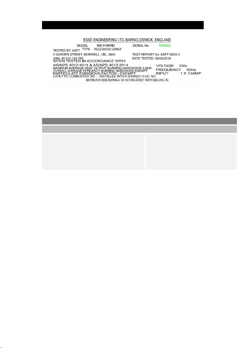
TECHNICAL DATA
Figure 1 990 Hybrid Data Plate
The cooker data plate is located behind the control panel.
Warning: This appliance is not suitable for installation in a shared flue system
TECHNICAL INFORMATION
Nominal heat output
5.0 kW
Minimum chimney
draught
12Pa
Combustion air
requirements
29 m3/h
Mean flue gas
temperature
170OC
Weight of appliance
400kg
Flue gas mass flow
10g/s

Page 6
HYB-AUS-I01-300419
CHIMNEY AND FLUE INFORMATION
The successful operation of the cooking appliance relies on the adequate
performance of the chimney to which it is connected. The following chimney
guidelines must be followed:
•If a flue liner is used, it should be 150mm (6’’) diameter and be made of
suitable material for burning wood. A Flue with a diameter of 150mm (6’’),
is required to connect to the cooker.
•Voids in the chimney should be avoided, as these will prevent a steady flue
draught. The appliance flue pipe should pass beyond the narrowing of the
chimney.
•The flue needs to be a minimum of 4.6m in height and terminate in
accordance with AS/NZS2918
•If the appliance is installed as a freestanding appliance, it should not
support any part of the chimney.
•Be free from cracks, severe bends, voids, and obstructions.
•Be connected to this one appliance only.
•New chimneys must be in accordance with local regulations.
•The chimney must be capped to prevent ingress of rain.
•A flue/chimney access point is required so that the state of the chimney
can be checked and any fallen soot removed.
•External flues must be insulated to prevent heat loss.
•Do not fit an extractor fan in the same room as the appliance.
Note: The chimney/flue to which this appliance is being connected must be swept
and examined for soundness prior to installation. Remedial action should be taken if
required, seeking expert advice if necessary. Where the chimney is believed to have
served an open fire installation it is possible that a higher flue gas temperature from
a closed appliance may loosen deposits that were firmly adhered, with the
consequent risk of flue blockage. It is therefore recommended that the chimney be
swept a second time within a month of regular use after installation.

Page 7
HYB-AUS-I01-300419
Figure 2 Chimney and Flue Performance

Page 8
HYB-AUS-I01-300419
Figure 3 Supplied Chimney Kit

Page 9
HYB-AUS-I01-300419
FLUE DRAUGHT
The flue draught should be checked before installation to ensure that the flue is free
of obstructions.
After installation two flue draught readings should be taken and recorded in these
instructions, one with the appliance at minimum burning rate and one at maximum
burning rate.
Minimum reading: The appliance should be lit and allowed to warm the flue
thoroughly. Close the air controls, and ensure firebox door is fully closed. Allow the
burning rate to become steady. The flue draught reading should now be taken; the
minimum required is 12 Pascals [Pa] (0.05’’ w.g.).
Maximum reading: The air controls can now be opened to allow the appliance to
burn at maximum rate. Take a flue draught reading.
Ideally, the flue draught readings should range between 12Pa, 0.12mm (0.05’’ w.g.)
and 24Pa, 2.5mm (0.1’’ w.g.). Any readings significantly outside this range may
indicate the need for remedial action. Low flue draught symptoms: difficult to light
and smoke coming into the room. High flue draught symptoms: fuel burns away very
quickly, over firing which may damage the appliance & invalidate the warranty.
A flue stabiliser can be fitted to reduce the draught through the appliance if the
draught is too high. The flue stabiliser should be fitted in the same room as the
appliance and be the same size as the flue pipe. Consult building regulations
regarding additional ventilation.
UNPACKING YOUR NEW COOKER.
Unpack your new Esse Cooker, removing all of the outer packing and accessories
from the top and bottom ovens, including protective film on the door liners. At this
time please examine the cooker for any damage to the enamel finish.
Any damage to the cooker or anything missing, please contact your supplier for
advice.
We ask that you dispose of any packaging in a safe responsible manner and recycle
where possible.

Page 10
HYB-AUS-I01-300419
INSTALLATION.
You must be aware of the following safety requirements & regulations:
This appliance shall be installed in accordance with the regulations in force and in a
well-ventilated space.
Read the instructions before installing or using this appliance.
The cooker must be installed in accordance with: All relevant AS/NZS Standards /
Codes of Practice and the relevant Building / IEE regulations
Do not use the towel rail as a lifting aid as damage will occur.
Location of the Oven
The appliance should be sited on non-combustible material.
This appliance is designed for domestic cooking only. Use for any other purpose
could invalidate any warranty or liability claim.
Flue Connection
The flue pipe used to connect the appliance to the chimney is 6’’ (150mm) in
diameter.
(The flue connection is on the top of the appliance, in the centre at the back.)
Important Notes
•The installation must allow access for adequate chimney sweeping and flue
cleaning.
•Avoid using bends greater than 45º to the vertical. All flue pipe sections
should be as close to the vertical as possible.
•All joints in the flue system must be effectively sealed.
•All flue sockets must face upwards. On completing the installation of the
appliance, the chimney, hearth and walls adjacent to the cooker must
conform to local or national regulations currently in force. (AS/NZS
2918/2018)
•Air inlet grilles should be positioned so that they are not liable to blockage.
•An air extraction device shall not be used in the same room as the
appliance unless adequate additional ventilation is provided.

Page 11
HYB-AUS-I01-300419
•A flue cleaning door should be fitted to provide access for cleaning the flue
and chimney.
•Check the appliance for soundness of seals between casting and main
components and that all supplied parts and fittings are correctly fitted.
•Ensure the appliance is left operational and hand over the operating
instructions and operating tools supplied.
•Before leaving the installation demonstrate the operation of the appliance
to the user. Explain all controls and flue way access for cleaning.
CONNECTING YOUR COOKER
For your own safety we recommend that a competent person installs your cooker.
This cooker is designed to be installed using a standard 15 Amp plug. A qualified
electrician is not required.
Electrical connection
Ovens with a three-pole power supply cable are designed to operate with alternated
current at the supply frequency and voltage indicated on the data plate (located
behind the control panel).
Connecting the power supply cable to the mains
The appliance is supplied fitted with a 1.5 metre cable and a normalized 13 amp plug
which correspond to the load indicated on the data plate. Before making the
connections check that: the circuit breakers or fuses of the home system can support
appliance load (see data plate), the power supply system has a sufficient earth
connection which complies with the provisions of current regulations and the law,
and there is easy access to the socket. Do not use reducers, adapters, or coiled
extensions as these could cause heating or burning.
Page 12
HYB-AUS-I01-300419
Figure 4 Possible Plug Locations
BEFORE USING YOUR COOKER
Remove plastic protective covers from inner door panels and lift up lid.
Before you cook for the first time, it is recommended that both ovens be switched
on to the highest setting for about an hour to burn off any initial odours
The grill should also be turned on for 15 minutes with the top oven door left open,
before it is used for the first time.
HOT WATER SYSTEM
A. If a boiler is fitted to this system it must be connected to a heating system
otherwise the warranty is void.
B. There are two connections, both 1” BSP Female on the left hand side. Follow
general notes below.
C. The D boiler is of stainless steel construction for use on an open vented indirect
system.
D. It is recommended that the system is connected using flexible connectors
and/or shut off valves which will allow the cooker to be moved forward for
maintenance

Page 13
HYB-AUS-I01-300419
E. General Notes on Water System: -
1. The cooker will produce hot water at differing rates depending on how it
is operated. Heating control is manual, no thermostat is fitted.
2. The system must be designed to cope with loads between the maximum
and minimum output. There must be sufficient gravity load to absorb
250L low pressure hot water output.
3. This unit is not approved for use with hydronic heating systems.
4. Whichever system is chosen the layout must follow established heating
engineering practice. To avoid trapping air in the boiler a 1” BSP
connection must be used on the flow and return tapping, and any
reduction in pipe size thereafter being made on a vertical rising pipe. The
cooker must be level when fitted and the flow pipe must rise from the
boiler.
5. The cylinder and pipe work should be lagged to avoid heat loss.
6. The static head must not exceed 18 meters.
7. A drain cock should be fitted to the lowest part of the circuit.
8. The total water capacity of the boiler is 4 litres.
9. A heat leak radiator should be fitted to absorb any excess heat that may
be produced.
10. The system must be open vented.
11. It is recommended that the system is sealed with hemp & paste or
equivalent which can withstand temperatures exceeding 100oC
Page 14
HYB-AUS-I01-300419
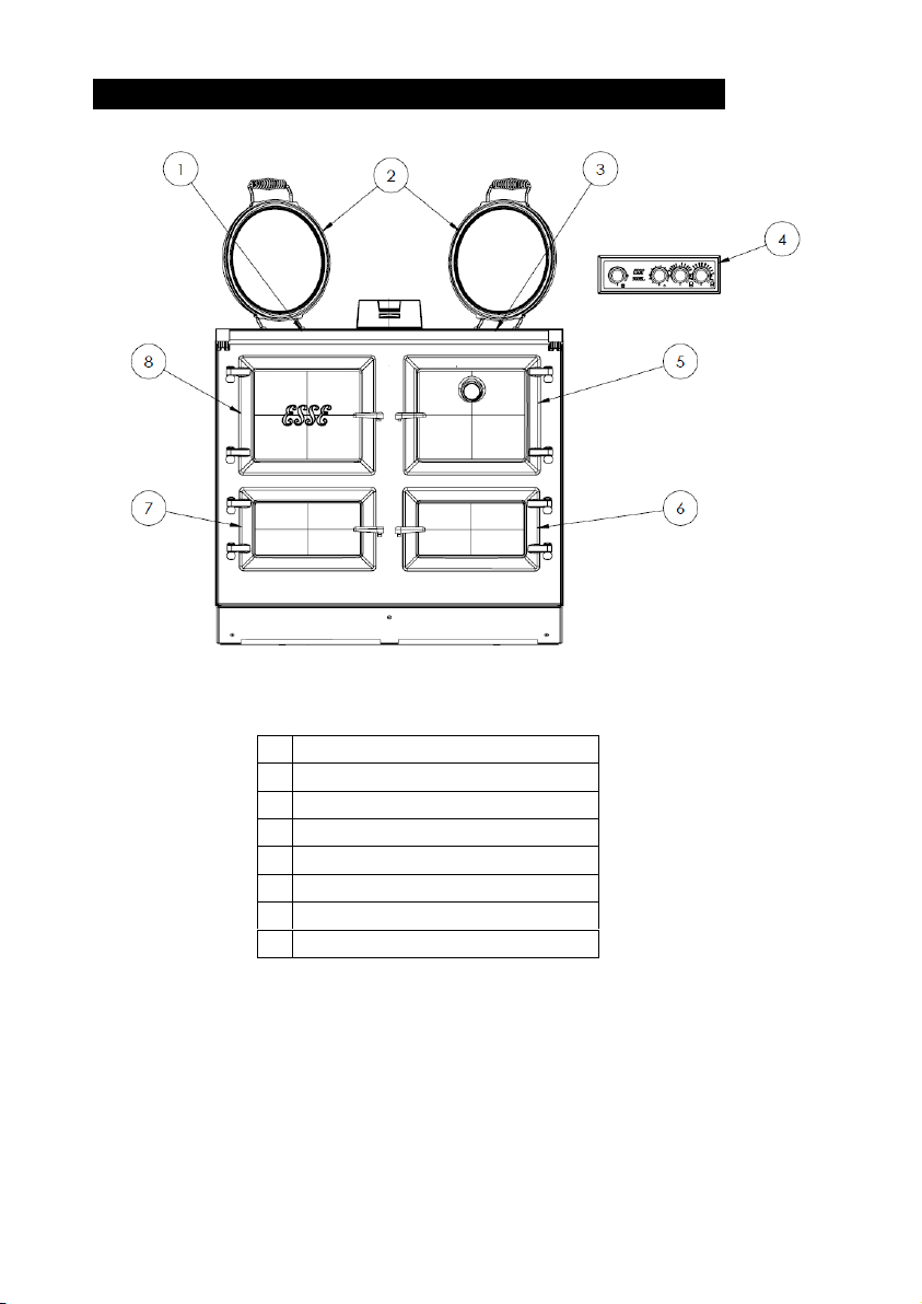
YOUR COOKER.
Figure 5 990 Hybrid Cooker
1
WOOD FIRED HOTPLATE
2
HEAT CONSERVING LIDS
3
ELECTRIC HOTPLATE
4
CONTROL PANEL
5
ELECTRIC TOP OVEN AND GRILL
6
ELECTRIC BOTTOM OVEN
7
WOOD FIRED BOTTOM OVEN
8
FIREBOX

Page 15
HYB-AUS-I01-300419
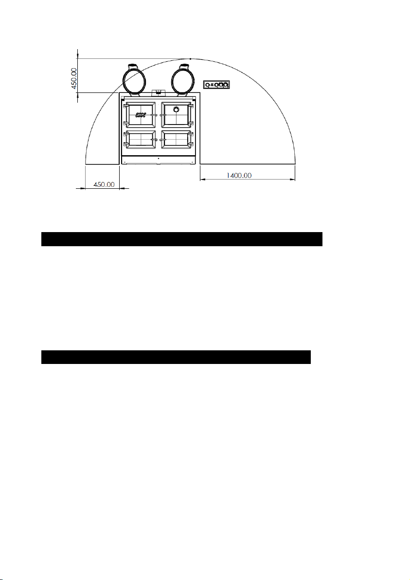
Figure 6 990 Hybrid Dimensions
SPACING AND DIMENSIONS.
All dimensions are in mm

Page 16
HYB-AUS-I01-300419
Figure 7 Clearances to Combustable Surfaces
General Information
The cooker is not to be grouted or sealed at the back or sides of the worktop as if
any maintenance is required the cooker will have to be pulled away from the wall at
the rear.
The cooker weighs 400kg and so the floor must be capable of withstanding the load.
Hearth requirements
A minimum 930mm deep x 990mm wide x 9mm thick floor protector (Bellis Board)
should be used under and in front of the appliance base when installing the appliance
(see joint AS/NZS 2918:2001 3.3.2).
The floor protector should extend 300mm in front of the appliance fuel loading door
and be placed centrally in the 990mm width.
The Thermal conductivity of the floor protector is 0.1m².K/W for 9mm thick sheets.
Page 17
HYB-AUS-I01-300419
Clearances
Combustible Rear Clearance : 175mm
oUsing a 6” Stainless ( painted Stainless or enamel flue is also
approved ) with a 180o Stainless Heat shield extending to the
900mm high
oNon Combustible Rear Clearance : 30mm
Side Clearance
oTo Combustible ( below hob / bench height ) 20mm
oTo Non Combustible ( below hob / bench height ) 10mm
oTo Combustible wall ( above hob ) 100mm
oTo Non Combustible wall ( above hob )10mm
Due to the hand crafted nature of the cooker all dimensions are ±2mm.
Before using your cooker remove plastic protective
covers from inner door panels and lift up lids.

Page 18
HYB-AUS-I01-300419
CONTROL PANEL
Figure 8 990 Hybrid Control Panel
The control panel cable is to be kept accessible and not
recessed into the wall if wall mounted
Figure 9 Control Panel Mounting Holes
Drill and plug the wall with suitable plugs. Ensure that the screws will fit the back
plate before drilling any holes. Ensure that the screw head remains proud of the wall
to allow the back plate to engage.
Page 19
HYB-AUS-I01-300419
ELECTRIC OVENS, GRILL, AND HOTPLATE
The electric ovens work by modulating the power between the cast iron hotplate,
the top oven, and the lower oven. If both ovens and the hotplate are on, the cooker
will modulate the power to reach the selected temperatures, but if only one oven or
the hotplate is turned on it will heat up more quickly.
The cooker is designed to be used on slumber mode for the majority of the day giving
off a constant background heat and can then heat up quickly to the required cooking
temperatures when required. However the cooker can simply be used as an On/Off
appliance if required.
The cooker consumes less than 1kW/Hr in slumber
mode at a room temperature of 18°C.
The top and bottom oven are controlled thermostatically and the temperature
markings on the controls are in °C. To switch one of the ovens on, turn the
corresponding knob clockwise to the desired temperature. The indicator light will
glow red to show that the oven is heating up and will glow green when the oven has
reached selected temperature. Similarly when the control is moved to a lower
temperature the red light will flash until the oven has reached the selected
temperature, once the selected temperature is reached the LED will glow green
again. The control shows a red flashing light after the oven has been switched off to
indicate residual heat.
The top oven
This oven has a patented 3kW wrap around element and a 3kW grill element. The
grill is a full width grill and takes priority over the top oven control. The Top oven
and grill can never be on together, if the grill control is on at any position, then the
top oven will not work until it the grill is switched off.
The thermometer in the top oven door is only a guide to actual oven temperature.
The reading will be incorrect when the door is or has been opened and will recover
once the door closed.
The lower oven
This oven has a patented 3kW wrap around element and is used as a smaller capacity,
high or low temperature oven.

Page 20
HYB-AUS-I01-300419
SAFETY POINTS
When using the oven shelves ensure they are placed correctly between the
shelf runners.
Always use oven gloves when removing food from either oven or the grill.
Cooker heat up times
From slumber the heat up times can be seen in the table below. These times have
been measured with all elements heating at once, if only fewer elements are heated
the time will be reduced.
Maximum Temp (oC)
Time Taken (Mins)
Top Oven
240
60
Bottom Oven
210
65
Hotplate
400
80
0
50
100
150
200
250
300
350
400
450
010 20 30 40 50 60 70 80 90 100 110 120 130 140
Temp (oC)
Time (Mins)
Heat Up Times
BOTTOM OVEN TOP OVEN HOT PLATE
Table of contents


