Essex Electronics Silver-Line SL-7 User manual

1
Read This Book
This book has important information for the use and safe operation of this machine. Failure to read this book
prior to operating or attempting any service or maintenance procedure for your Silver-Line machine could
result in injury to you or to other personnel: damage to the machine or to other property could occur as well.
You must have training in the operation of this mac
hine before using it. If you or your operator(s) cannot read
English, have this manual explained fully before attempting to operate this machine.
All directions given in this book are seen from operator’s position at the rear of the machine.
Essex Silver-Line Corporation, 1118 Lakeview Ave. PO Box 40, Dracut, MA 01826
www.essex-silver-line.com
Silver-Line SL-7
Operator’s Manual

2
The Silver-Line SL-7 Floor Edger
(Suggestions for Care & Operation…Parts List)
Introducing:
Your new Silver-Line SL-7 edger is the easiest and fastest cutting edger available to the professional and rental
trades. It is complete and ready to operate having been adjusted and thoroughly tested at the factory. The following
suggestions will assure your getting the long life and excellent performance engineered into each and every machine.
Inspect:
Check the shipping cartons for any signs of damage and inspect the machine and its parts for any possible damage.
Assemble:
Assemble the machine by attaching the dust tube elbow to the back of the edger with the screws provided. Place
the bag over the support and secure it tightly with the Velcro strap to the neck of the dust tube. Please be advised that a
new bag will not fully expand until it is fully cured. The curing process will be completed with use.
Voltage:
The voltage is indicated on the nameplate. Lay the edger on its side, be sure the switch is turned OFF and plug
into the proper current. Use of current other than specified will damage the motor. When additional extension cords are
required use only 12/3 heavy-duty cord.
Starting:
To start your new edger just tilt it back so the disc is off the floor and turn switch on. Lower the edger onto work
carefully keeping machine in motion while it is running. The weight of the SL-7 is precisely balanced to produce maximum
results without additional pressure for every scope of work.
Lubrication: Note: Your SL-7 is completely lubricated and ready to use when shipped from the factory!
The ball bearings used in the production of this edger are sealed and no further attention is required for their life.
The gears are made of a special alloy; heat-treated and under normal service require lubrication about four times a year. To
lubricate the SL-7 remove the grease plug and put approximately 1/3 of a one shot tube of grease (C7-84) into the hole.
Turn the machine on and let the extra grease come back out the hole. If the machine does not kick any grease out add more
grease. Repeat this process until the edger is fully greased, reinstall the plug and clean any grease on the machine.
Dust Collecting:
The dust collection system will be most efficient when the bag is emptied when it is 1/3 to ½ full. Remember to
remove all sawdust from the house. Paper or any foreign obstruction can be easily removed by taking the dust tube off.
Disc Pad:
The disc pad installed on your new SL-7 edger has been aligned in the factory to make the best possible cut and
get the best dust pick up. Adjusting the cut on your edger is easy using a set of castor adjusting bars (C7-87). From the
operators position, the space between the caster bracket and bearing shoulder should be approximately ¼” on the left and
3/16” on the right.
Motor:
The motor commutator may be smoothed if it becomes necessary. Remove the two screws from the front cover
tag and insert the proper stone through the slot you exposed. Replace the cover for proper ventilation.
Disc Guard:
The disc guard on the SL-7 should move freely enabling the user to sand upto baseboards and edges safetly. Dust
and dirt may effect its movement and you clean itout periodically. For cleaning remove the disc pad, disc guard ring and the
disc guard. Blow out dust and dirt, dry clean only, do not use lubricant. Reinstall the parts you removed.
Wiring: Please check the wiring and cords before using or renting this machine
Questions: Please call us @ 1 800 451-5560 or email our website www.essex-silver-line.comif we can answer any questions.
Warranty: Please fill out the enclosed warranty card, tear at the perforation and mail the proper section to our Dracut, MA
plant.

3
SL-7 Floor Edger Parts Price List
Part # Description Cost Part # Description Cost
C70 SL-7 Carrying Box (Wood) $60.00 C7-28 Wheel Bracket $32.90
C71 Motor Frame $177.10 C728B4 Bumper
C72 Gear Housing $151.80 C728D Dustless Bracket $42.15
C72D Gear Housing (Dustless) $156.80 C728D-4
Glides (Dustless) $4.00
C72D2 Nylon Glide (Snap On) $0.00 C729 Nut-Lockout $0.70
C73 Gear Housing Cover $50.60 C730 Short Cord Assembly $23.40
C74 Motor HousingCap $36.70 C730A Short Cord Only $4.75
C75 Lamp Shield $22.75 C731 Cord Only (25') $24.05
C76R Handle (Right) $39.20 C732 Male Twist Lock (3 Wire) $7.50
C76L Handle (Left) $34.15 C733 StrainReliever $6.35
C77 Dust Tube $44.30 C734 Lamp Socket $5.05
C77Y Exhaust Tube (Dustless) $29.97 C735 Lamp $1.25
C78 Vacuum Fan $24.00 C735220
Lamp (220V) $4.25
C79 Baffle Plate $10.10 C736 BagSupport $8.75
C710 Gear (Large) $84.75 C736A StrainReliever $1.79
C711 Gear (Small) $30.35 C737 Collar $1.90
C712 Bearing Plate $30.35 C738 Dust Bag $13.80
C712A Load Spring $1.90 C738R Dust Bag (Reinforced) $14.80
C713 Screw (Nameplate) $0.40 C739 Screw (Motor Cap) $0.30
C716 Armature (115 Volt) $139.15 C740 Bearing #1 (Comm) 6201 $8.85
C716220
220 Volt Armature $150.00 C741 Bearing #2 (Fan End) 6202 $9.50
C716240
240 Volt (50Hz) Armature $150.00 C742 GreasePlug $3.15
C716A Armature w/Baffle & Vacuum Fan $177.10 C743 Key (Small Gear) $0.90
C716B Cooling Fan (Press On) $15.46 C744 Screw (Shield) $0.30
C716D Spacer (Replaces Grease Slinger) $3.50 C745 Nut (Left Handed) $3.65
C717 Field $60.70 C746 Shield $12.65
C717A Field (240V, 50hz) $65.70 C747 Screw (Baffle & Vent) $0.30
C717B Field Clips $0.50 C748 Screw (Housing) $0.30
C718 Brush Holder $8.35 C749 Caster Assembly (Complete) $30.35
C719 Brush Cap $1.90 C749C1 Stem $3.60
C719A Brush Cap (Old Style) $2.30 C750 Screw $0.30
C720 Brush $6.25 C751 Handle Screw & Washer $3.15
C721 Insulator (Not pictured, obsolete) $0.30 C760 Cord Complete $33.00
C722 Screw (Field) $0.60 C760220
Cord Complete (220v) $67.95
C723 Nameplate (Front) $2.30 C761 Bearing #3 (Upper Jackshaft) 6203 $9.50
C724 Switch $13.80 C762 Jackshaft $46.45
C725 Screw (Lamp Socket) $0.30 C763 Key $0.90
C726 Spacer (New Style) $5.70 C764 Fiber Washer $0.30
C727 Ventura Plate $5.05 C765 Disc Guard Ring $24.65
Essex Silver-Line Corporation Toll Free 800 451-5560
1118 Lakeview Ave. Fax (978) 957-6989
PO Box 40 Phone (978) 957-2116

4
Dracut, MA 01826 www.essex-silver-line.com
Part # Description Cost www.essex-silver-line.com
C766 Screw (Disc Guard) $0.30
C767 Disc Guard $25.60
C767B 1/2 Moon Baffle Plate $6.50
C768 Disc Pad $67.85
C768R Disc Pad (Refurbished) $33.93
C769 Paper RetainingWasher $3.60
C770 Paper Retaining Bolt $2.35
C771 Bearing #4 (Lower Jackshaft) 6204 $8.85
C772 Screw (Gear Cover) $0.30
C773 Screw (Dust Tube) $0.30
C774 Screw (Brush Holder) $0.30
C775 Wrench Clip $3.15
C776 Screw (Wrench Clip) $0.95
C778 Wrench $10.10
C779 Plug (Male Straight) #1447 $7.00
C780 Plug (Female Twistlok) #4729C $12.00
C781 Nameplate (Top) $1.80 Silver-Line SL-7 Edger
C782 Disc Cutter (7") $60.70
C782A Cutter Blade $7.60
C782B Center Punch $5.70
C782D2 Nylon Bar (2) $25.00
C782D3 Threaded Nylon Washer $0.00
C784 Grease (One Shot Tube) $3.80
C785 Gear Housing Cover Remover $10.30
C786 Disc Pad Remover $11.45
C787 Caster Adjusting Bars $9.15
C787A ProtectiveScreen $0.00
C788 Clarke Disc Spacers $5.05
C789 Clarke Edger Wrenches $11.40
C790 Quarts Edger Grease $13.15
C791 White Nylon Washers (Spacers) $0.10
C792 Tool Repair Kit $29.95
C793 Motor/Gear Housing Seperator Tool $40.00
ADP American Disc Pad (B2) $67.85
CB Clarke Edger Bolts $2.35
CP Clarke Disc Pad $67.85
CW Clarke Edger Washers $3.60
SL-7 Floor Edger Parts Price List

5

6
Simple Preventive Maintenance
Will save you money and keep your working equipment sound
Blow out the dust from you edger after every use. Make sure to blow out around the disc pad,
guard, brushes and the hole for the paper retaining screw.
Grease you machine every 2 to 3 months depending upon usage.
Check motor brushes every three months the first year and keep the brush holder free from dust.
Check brushes more often the 2nd year. Replace brushes when ¼” long.
Check the disc pad often for wear; replace it when worn, as it will save wear and tear on you
machine.
Check center hole (jackshaft) on the disc pad for accumulation of dust and grit. Do Not let it build
up in this hole. Clean it out so that you get full movement from the bolt. The disc washer should
not move when holding paper.
Check you cable, electrical equipment, plug, etc. before sending it out. This saves you time, money
and headaches.
Check dust bags for worn or torn spots. Keep the dust bag clean and in good condition.
Check dust collection; do not let it get blocked.
Check the casters on the SL-7, they are adjusted in the factory to make the machine cut correctly.
You should keep the casters blown out so they move freely. The caster stems should be straight.
If the stem is bent, try to straighten it, but you may need to replace the unit.
Service and repair notes for Whippet C7 & ESL SL-7 edgers:
Whippet edgers from serial #’s 1 to 661 do not have armatures or fields available.
Whippet and Silver-Line edgers with serial #’s from 662 to 1256 use the old style armatures and
require a grease slinger (spacer). You may replace the old style armature and field with the present
units. When you upgrade the grease slinger is no longer required.
Load spring part # C712A should be used with all edgers and fits on top of the bearing plate
(C712), and over the top bearing.
The old style brush holder is no longer available. This used a brush ring and insulator (C721).
Please identify style when ordering.
When ordering a disc guard please note which style you need, stationary or rotating. Your new
parts list shows the rotating parts. As of 01/2001 the stationary gear housing cover is not
available, purchase a new gear housing cover and guard. At this time the stationary disc guard
(C767A) is still available, when our supply is depleted this part will be discontinued.
Adjusting the Cut on the SL-7 Edger
1) Locate yourself behind the unit as if you were going to run it. The space between the bearing shoulder and caster bracket
should be ¼” on the left and 3/16” on the right.
2) Caster adjusting bars (C787) can be used to check the spacing.
3) If your casters are not spaced correctly loosen the retaining nut and move the caster with a screwdriver. Check the
spacing and tighten the nut when it is in the correct position.
4) The adjustments are easier to make when the edger is located on the edge of a table with the casters overhanging.
5) Run your new disc pad against a piece of 100 grit paper to remove high spots and rubber nubs that result from
manufacturing. Run until the pad runs smooth, with no vibration.
6) Your edger should make a pie slice cut from twelve fifteen to one o’clock on the floor.

7
SL-7 Floor Edger
Repair/Maintenance
Instructions
1. Disc Pad Removal
2. Brush Replacement
3. Bearing Replacement
4. Adding Grease
5. Tap out Jackshaft for Bolt & Washer
6. Clean Armature Commutator
Before attempting any repairs on your Silver-Line SL-7 edger disconnect it from power.
The tools referred to in these instructions are available from Essex Silver-Line Corporation,
call us @ 800 451-5560 and ask for each tool separately or as a kit part # C7-92.
1) Disc pad Removal: The disc pad is threaded onto the jackshaft in a clockwise motion!
a) Remove dust tube exposing the vacuum fan on the armature. (4 screws) (Fig. A)
b) Turn edger upside down, resting on the flat top of the SL-7.
c) Block the fan with the handle of a hammer or screwdriver to stop the armature from
moving.
d) Line up the bolts of the disc pad remover with the holes on the disc pad, and insert them
into the disc pad.
e) Using a hammer, tap the disc pad remover counterclockwise to remove the old disc pad.
f) The disc pad should thread off the jackshaft.
Note: The jackshaft has interior and exterior threads. The interior accepts the bolt and washer
while the exterior threads are for the disc pad! (Fig. B)
2) Carbon Brush Replacement:
a) Remove brush caps using flathead screwdriver. Be careful not to damage the slots on the
caps.
b) Remove the old brushes and blow out edger with compressed air. The brush holders should
be blown out periodically as a part of maintenance.
c) Install the new brushes and reinstall the brush caps.
d) Run the unit to break in the new brushes.
3) Replacement of Bearings:
a) C7-40 (6201) Top bearing
i) Remove cover (C7-4) and load spring (C7-12a) (4 screws). Be careful to see how the load
spring comes outof the machine so you can put it back in the proper position.
ii) Mark the top of the Bearing plate (C7-12) with a magic marker to show which side is top.
Remove the bearing plate with a set of pullers.
iii) Remove the bearing with pullers.
iv) Tap a new bearing onto the armature (6201).
v) Reinstall the bearing plate, load spring, cover and screws.

8
b) C7-41 (6202) Located on the bottom of the armature, You must take the edger apart &
remove the armature to replace this bearing.
i) Remove disc pad (See #1)
ii) Remove the disc guard ring (C7-65), and disc guard (C7-67) (5 screws)
iii) Remove the 6 flat head screws holding the gear housing cover (C7-3) in place.
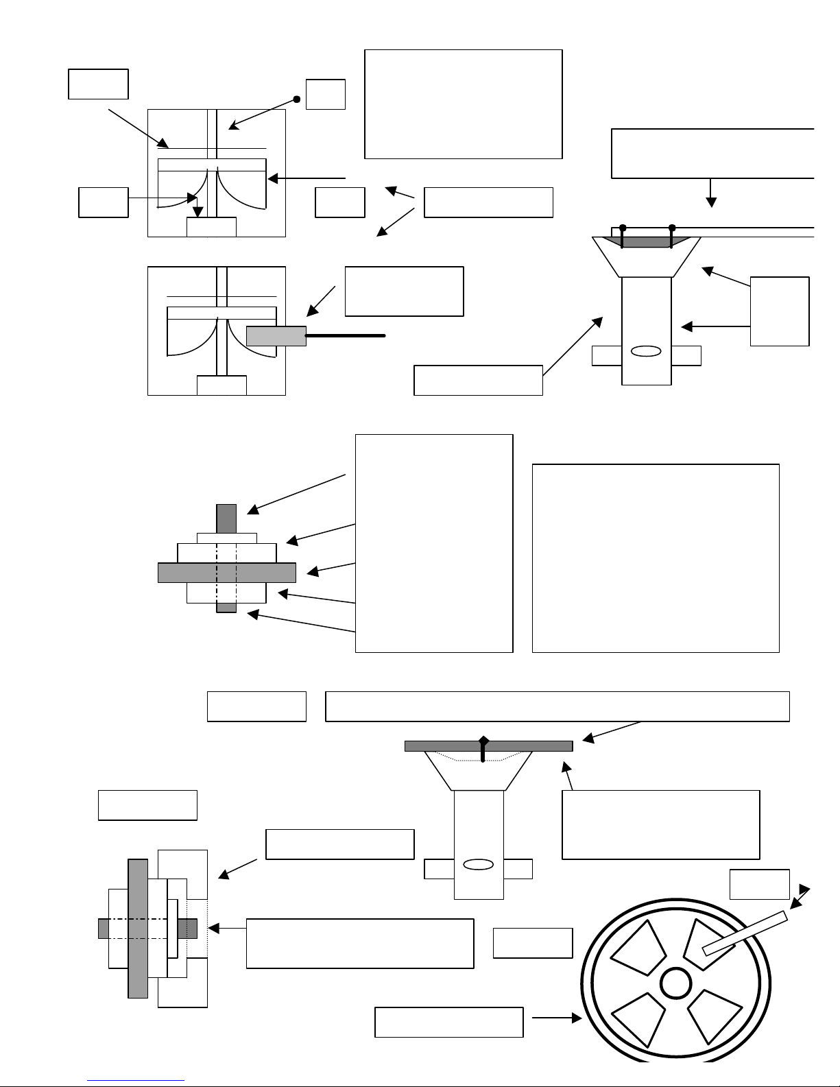
iv) Using the gear housing cover remover (C7-85) pull the jackshaft, gears and gear housing
cover out of the machine. (Fig. C) Remove the gear housing remover and tap the
jackshaft out of the gear housing cover. (Fig. D)
v) Clean the grease from the base to avoid a mess.
vi) Turn the machine upright.
vii) Remove cover (C7-4) and load spring (C7-12a) (4 screws). Be careful to see how the load
spring comes out of the machine so you can put it back in the proper position.
viii)Mark the top of the Bearing plate (C7-12) with a magic marker to show which side is top.
Remove the bearing plate with a set of pullers.
ix) Remove four housing screws (C7-48) that hold the motor frame (C7-1) to the gear
housing (C7-2).
x) Hold the motor frame on your hip with the lamp shield C7-5) facing out. Gently tap the
gear housing away from the motor frame using a rubber mallet; rotate the housing as
you hit it. The bearing at the base of the armature (C7-41) is seated in the gear
housing, holding the armature in place.
xi) Once the base is remove, flip the motor frame upside down and remove four screws (C7-
47) holding the baffle plate to the motor frame. Pull the armature out of the frame.
xii) Remove the LH nut (C7-45) on the end of the armature. Note the shoulder of this nut
has been machined, the small end face towards the gear. Remove the small gear (C7-11),
spacer (C7-26) and finally the bearing C7-41, (6202).
xiii)Replace the defective bearing and rebuild the armature.
xiv)Reinstall the armature into the motor frame and secure with the four bolts (C7-47).
xv) Line up the bearing (C7-41) with the bearing seat located in the gear housing (C7-2), tap
the top bearing (C7-40) straight down so the bearing is lowered into the seat. Line up
the holes in the motor frame and gear housing and reattach with the bolts (C7-48).
xvi)Turn the unit upside down, and grease the gear housing, small gear and large gear.
xvii) Line the jackshaft up with the gear housing and mesh the large and small gear teeth.
Gently tap the jackshaft back into the gear housing, allowing bearing #3 (C7-61) to be
inserted into its seat. The jackshaft will be install to the correct depth when the teeth
of the two gears are at the same height.
xviii) Line up the gear housing cover with the gear housing and bearing #4 (C7-71) and tap
it back in place. You may want to use a bolt to keep the cover lined up with the holes.
Screw the bolts back into the cover.
xix) Flip the machine over and reinstall the bearing plate, load spring and Cover.
xx) Flip the machine over again, resting on the cover (C7-4) and reinstall the disc guard, disc
guard retainer and disc pad.
c) C7-61 (6203) & C7-71 (6204) Located on the jackshaft.
i) Repeats steps 1-4 for replacing C7-41.
ii) Remove the LH nut from the jackshaft.
iii) Gently tap or press the jackshaft through C7-61 (6203) bearing.
iv) Remove large gear (C7-10) and key. Clean gear and check for wear.

9
v) Gently tap or press the jackshaft through C7-71 (6204) bearing.
vi) Rebuild jackshaft assembly with new bearings. Replace gear if necessary. Note: Check
interior threads on jackshaft for excessive wear and replace it before you rebuild it!
vii) Repeat steps 16-18 for replacing C7-41.
viii)Reinstall the disc guard, disc guard retainer and disc pad.
4) Add Grease:
a) Remove grease plug (C7-42) and clean out hole in center.
b) Insert one shot tube of grease into hole and squeeze a small amount into edger.
c) Connect the edger to power, hold it so the disc pad is off the floor and turn on the edger.
Let the edger spread the grease over and between the gears.
d) Shut down the edger and add a little grease. Turn on the edger, repeating until the edger
pushes grease out the hole.
e) Clean the grease off the edger and replace the grease plug (C7-42).
5) Tap out Jackshaft for Bolt & Washer:
a) Turn the edger over and set it on its top.
b) Using compressed air, blow out jackshaft
c) Using a small bit, drill out built up grit and paper at the bottom of jackshaft. Drill straight
down to avoid the threaded sides of the interior jackshaft.
d) Repeat b & c as needed.
e) Tap the jackshaft with a 5/16-18” Tap.
f) Test depth with new bolt (C7-70) from Essex Silver-Line Corporation.
6) Clean Armature Commutator:
a) Remove disc pad, disc guard and disc guard retainer.
b) Remove motor cap and load spring.
c) Secure bearing plate (C7-12) with one screw.
d) Turn on edger.
e) Using commutator stone, clean black carbon residue off the commutator through the holes
in the bearing plate. (Fig. E)
f) Clean until proper copper color shows.
g) Reassemble the machine.
Problem: Edger seems to be running loud?
Answer: Grease gears as needed.
Problem: Squealing noise!
Solution: Check and replace bearings as needed.
1st remove the dust tube and look down into bearing seat holding C7-41. If you see an
accumulation of sawdust than the bearing probably needs to be replaced.
2nd, if bottom bearing C7-41 looks clean, check the top bearing C7-40 by removing the cap,
load spring and bearing plate and test the bearing for wear.

10
Figure A
#1) Armature
#2) Baffle Plate
#3) Vacuum Fan
#4) Bearing Seat (C7-41)
#1
#2
#3#4
Screwdriver
holding fan
Hit disc pad remover w/hamm
er
Counterclockwise
Back of edger
Front of Edger
C7-2
C7-1
Figure B
C7-62 Jackshaft
C7-71 (6204) Bearing
C7-10 Large Gear
C7-61 (6203) Bearing
C7-45 (LH) Nut
Note:
C7
-
62 Jackshaft has threads on
the interior and exterior of section
shown on the top of this diagram.
The exterior thread
accepts the disc pad.
The interior threads
accept the bolt & washer to hold
paper.
Tap plate up from bottom
w/hammer to remove
jackshaft asse
mbly
Secure gear housing cover remover w/bolt & washer into jackshaft
Figure C
Figure D
Tap the jackshaft assembly
through the Gear housing cover
C7-3 Gear Housing
C7-12 Bearing Plate
Stone
Figure
E

11
Proper Application & Use of
Silver-Line Abrasives
12, 16, 20* grit Sheets & Discs
For removing old surface coatings and leveling uneven floors
36, 40* grit Sheets & Discs
For intermediate sanding of floors following rough sanding.
For initial sanding of moderately worn floors
60*, 80, 100* grit Sheets & Discs
For finish sanding of all floors prior to applying new coatings
For removing light scratches, sanding marks and minor surface damage
60, 80, 100, 120, 150 & 180 grit Sandscreens
For removing fine scratch marks prior to applying new coatings
For light sanding between surface coatings
*Indicates most popular rental grits for sanding floors. 60 & 100 grit should be used in succession
for proper finish. Never skip more than two grits when sanding a floor.
Example: Do not jump from 36 grit to 80 or 100 grit
Always start your sanding project with the highest possible grit that will cut and level your floor.
If the grit will not cut the finish or level the floor, go down one grit size to complete the cut!
White* Thick Nylon Pads
Buffing, for polishing floors where highest luster is desired
Green Thick Nylon Pads
Scrubbing, for general duty scrubbing and spot removal on floors
Black Thick Nylon Pads
Stripping, for heavy duty wet stripping of floors
* White pads should be used under the padlocks when using sandscreens on rotary
and orbital polishers. They are used for driving sandpaper on Orbital Polishers.

12
Wood Floor Refinishing
The Silver-Line Way
(Visit our website www.essex-silver-line.comunder consumer tips for complete information)
Job Preparation:
Remove the furniture, wall hangings, etc. Clear the room out!
Remove the old carpet, carpet pad and carpet strip (where necessary)
Locate & Reserve only Silver-Line Sanders & Edgers from your local rental store
Watch the Silver-Line “How to” Video
Inspect the floor for and remove…
Staples from the carpet pad
Nails from the tackstrip
Nails protruding from the floor (countersink these nails)
Make sure you are very diligent when completing this task, protect the rental machine!
You may be liable for damage to the drum and disc pad on the rental equipment!
Protect the rest of your house from sawdust, sweep the floor and vacuum, and pick up the equipment!
Sanding the Floor:
What are you trying to accomplish during thisproject? First, you want to level the floor, and remove the old finish. The
remaining cuts or passes are to remove the scratch marks made by the previous cuts. Do not skip too many grits when
sanding the floor, as the finer grits may not be able to remove the heavier scratches.
Start the process with the highest grit possible to complete the first cut, leveling and removing the finish. If a 36 or 40
grit will accomplish the task, then do not use 20 grit or heavier. If it seems to be taking too long, drop down and use the
heavier grit. By doing this you will probably save time.
Break the room down into two sections, 1/3 to 2/3 and sand the larger area first. Complete the 2/3 section and turn around
to sand the remaining 1/3. Do this with all the grits. Offset where you stop and start the sanding so you do not end up with
a line across your floor at the end of the project.
Use the SL-8 sander for the main section of the floor and then follow with the SL-7 edger. This method will allow you to set
the level you want in the main section of the floor and than bring it out to the edge of the room with the SL-7.
To use the Silver-LineSL-8 correctly, you sand forward and backward on the same line with the SL-8 sander. Be sure to lift
up on the handle with enough force to keep the drum pressure constant on the floor. Feather the sander so the drum comes
off the floor while moving forward or backward when you reach an area that you need to stop.
The following grits are recommended for a professional looking sanding job. Again, you want to start with the least
aggressive grit to complete the leveling and finish removal and proceed up through the grits.
20, 36 or 40, 60 and finally 100
2/3
1/3
Sand First
Sand Second
Floor Sanded
Level w/SL-8
Bring this level
to wall w/SL-7

13
Note: If you trip a beaker or blow fuse, turn off the equipment off, then reset the breaker or
replace the fuse.
Note: Remove all sawdust from the house as you empty the dust bags. Empty your sander bags
when they are ½ full, this will help with the dustpick up. Sawdust can be flammable and you do not
want it in your house.
Note: When using the SL-7 edger, sand from right to left and let the edger do the work. A
properly aligned edger, with a disc pad in good condition will function well without the user exerting
additional pressure. Let the edger do the work; don’t put extra pressure on the machine. Work at
a pace you are comfortable with, and take frequent rests.
If the cutting action of you sander seems to slow or diminish, it is probablytime to change the sandpaper. In an effort to
save money, don’t try to extend the life of the paper, replace it as needed. If you skimp on the amount of paper you use on
this project it will affect the end result. Don’t look at the cost at the time of sanding, but rather over the life of the floor.
Replace abrasives to get the same type of cut across the floor.
After you sand the floor with the SL-8 & SL-7 it is time to scrape corners, door jambs, etc. Use our 12 wood handle scraper
with a 1” Red Devil blade, available from the rental store, to accomplish this task. Hand sand the areas you scraped.
If you have areas such as baseboard heat, radiators or toekicks that could not be reached by the SL-7, use the Silver-Line
U2 underradiator sander to clean up these areas. It uses 5” PSA discs and is also available at the rental store.
When your done sanding your floor return your sanders to the rental store. Remember to return the cords, wrenches, bags
and unused supplies.
Note: After sanding you should screen the floor before you apply any finish or stain to achieve the
best possible finish. A professional floor sander will screen his work; spend the time and money to
screen your floor.
Essex Silver-Line Corporation
PO Box 40
1118 Lakeview Ave.
Dracut, MA 01826
(978) 957-2116, Fax (9780 957-6989
Toll Free 800 451-5560
www.essex-silver-line.com

14
Essex Silver-Line Corporation
Limited One Year Warranty
Essex Silver-Line Corporation warrants the floor sanding equipment for a period of
one year from the date of original purchase. We will repair or replace at our
option, any part or parts of the products under this warranty which examination
proves to be defective in workmanship or materials during the warranty period.
For repair, return machine or parts to Essex Silver-Line Corporation
transportation prepaid. This warranty does not apply to repair or replacement
required due to misuse, abuse, normal wear and tear and/or repairs attempted or
made by other than our service center. For the purpose of this warranty, damage
resulting from accident, use of defective or inadequate wiring at the installation in
which used, improper cleaning or operation, fire, floods or act of God, are not
covered. No other warranty implied or expressed is offered and under no
circumstances shall Essex Silver-Line Corporation be liable for an incidental or
consequential damage.
Essex Silver-Line Corporation
PO Box 40
1118 Lakeview Ave
Dracut, MA 01826
(978) 957-2116, Fax (978) 957-6989
Toll Free 800 451-5560
www.essex-silver-line.com
Table of contents