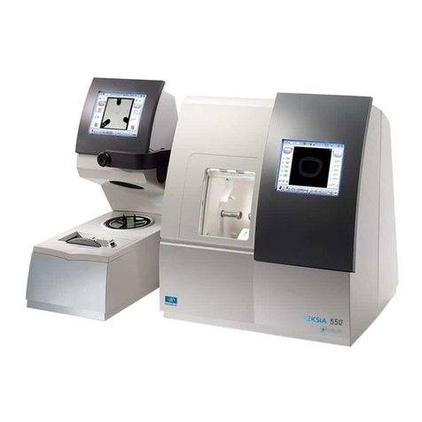
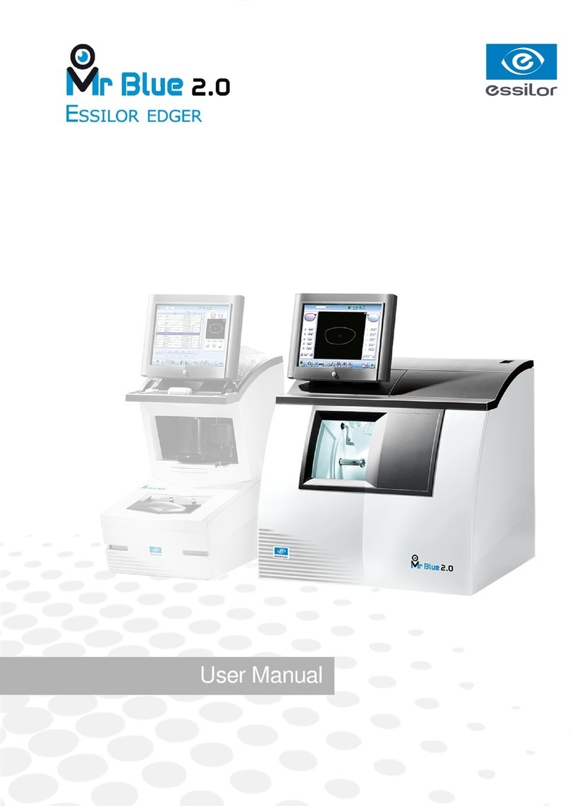
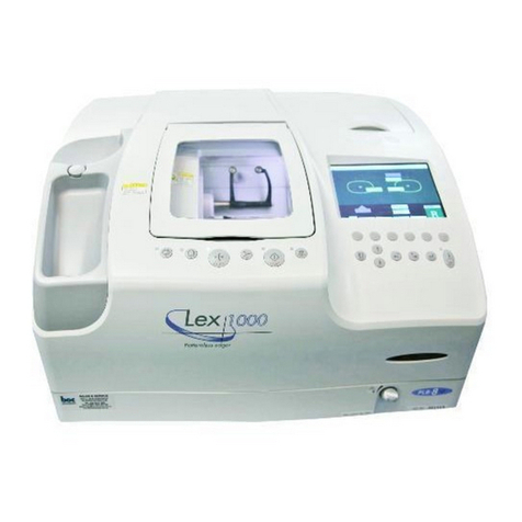
Essilor Delta 2 Classic User manual

User Manual


USER MANUAL > CONTENTS
CONTENTS
I. INTRODUCTION 7
II. FIRST STEPS WITH DELTA 2 11
1. Descriptive diagrams 13
2. Instructions for use 15
a. Turn on the product 15
b. Turn off the product 15
c. Using the touch screen and keypads 15
d. Work screens 17
III. CARRY OUT AN OPTICAL TRACING 19
1. The tracing environment 21
a. Menu screen 21
b. Jobs and working modes 22
2. Shape management and storage 24
a. Menu screen 24
b. Job list 25
c. Creating a job 26
d. Working in current job mode (job A) 27
3. Optical tracing 27
4. Enter the curve and frame base 31
5. Case of a mechanical tracing 32
a. Connection with a PHI tracer 32
b. Connection with a Tess tracer 33
IV. CENTER AND BLOCK A LENS 35
1. Centering environment 37
a. Description of the centering blocking system 37
b. Menu screen 41
c. Calling up a shape 43
2. Centering a lens for a high-base frame 44
3. Centering a single vision lens 44
4. Centering a progressive lens 46
a. Centering a progressive lens using re-marked micro-engravings 47
b. Centering a lens using manufacturer markings 48
5. Centering bifocal / trifocal lenses 50
6. Centering an executive lens 51
7. Centering a mid-distance lens 53
a. Centering a lens using re-marked micro-engravings 54
b. Centering a lens using manufacturer markings 55
8. Blocking a lens 57
a. Prepare blocking 57
b. Blocking 59
V. MODIFYING THE LENS SHAPE 63
1. Menu screen 65
2. Modifying a shape 66
a. Enlarging, reducing or rotating a shape 66
b. Free-form modification 68

USER MANUAL > CONTENTS
c. Retouching a shape 69
3. Archiving/saving a shape 70
VI. PREPARING A DRILLED JOB 71
1. Menu screen 73
2. Configuring a drilling point 75
a. Creating a drilling point 75
b. Delete one drilling point 75
c. Dimensioning a drilling point 76
d. Adjusting the position of a drilling point 77
3. Drilling models 79
a. Importing a model 79
b. Saving a model 80
VII. EDGING A LENS 81
1. Edger working environment 83
a. Menu screen 83
b. Calling up a shape 85
c. Lens set-up and feeling 85
2. Perform a Beveling 86
a. Automatic beveling 87
b. Legend screen for customized bevels 87
c. Customized beveling 88
d. Modifying the bevel curve 89
e. Modifying the bevel curve at a particular point 90
f. Displacing the bevel curve 91
3. Grooving 91
a. Automatic grooving 92
b. Customized groove legend screen 93
c. Customized grooving 94
d. Modifying the groove curve 95
e. Modifying a point in the groove curve 96
f. Displacement of the groove curve 96
4. Flat-edge finishing 97
5. Perform a drilling job 97
a. Automatic drilling 98
b. Legend screen for customized drilling 99
c. Customized drilling 101
6. Polishing 102
7. Chamfering 102
8. Perform a Retouching 103
VIII. SET THE EDGING SYSTEM 105
1. Configure the tracer-centerer-blocker and the edger 107
a. Time, date and language 107
b. Screensaver 108
c. Connections 109
2. Customize the tracer and the centering device 110
a. Working modes and display precision 110
b. Decentration mode 111
c. Action bar 112
d. Brightness 113
3. Adjusting the precision of the edger 114
a. Adjusting the diameter of the finished lenses 114
b. Adjusting the position of the bevel and groove 115

USER MANUAL > CONTENTS
c. Adjusting the diameter of drill-holes 115
d. Adjusting the chamfer 116
e. Adjusting the groove 117
4. Restoring the factory settings 117
IX. MAINTENANCE & SERVICING 119
1. Perform the autotest of the tracer 121
2. Performing the edger autotest 123
3. Checking and calibrating the tracer 124
a. Calibrating the touch screen 124
b. Control and calibrate the centering device 125
c. Control and calibrate the blocker 126
d. Check the optical system 127
4. Testing and calibrating the edger 128
a. Control the calibration of the monofeeler 128
b. Calibrating the touch screen 129
5. Statistics and technical history of the tracer 129
a. Tracer-centerer-blocker statistics 129
b. Technical history and errors 132
6. Statistics and technical history of the edger 133
a. Edger cycles 133
b. Technical history and errors 134
7. Make a backup of the jobs and display configuration 135
8. Changing or cleaning the blocking tube 137
9. Changing or cleaning the edger tools 139
a. Changing or cleaning the drill bit 139
b. Changing the grooving or chamfering wheel 140
10. Maintain and clean the tracer-centerer-blocker 142
a. Precautions required 142
b. Clean the reflectors and the lens 142
c. Clean the tube 142
11. Maintaining and cleaning the edger 142
a. Precautions required 142
b. Clean the GCD module 143
c. Dismantle and clean the door 143
d. Dress the wheels 144
TECHNICAL DATA 147
1. Environment 148
2. General features 148
3. “Tracer centering device blocker” Function 148
4. “Edger” function 149
GENERAL INFORMATION 151
1. Symbols 152
2. Modifications 152
3. Declaration of conformity 152
4. Copyright 152
5. Materials and products 152
6. Safety instructions: 153
7. Electromagnetic waves 153
GLOSSARY 155

USER MANUAL > CONTENTS

I. INTRODUCTION

USER MANUAL > INTRODUCTION
8Delta 2 - Edging system > v2 - 08.16

USER MANUAL > INTRODUCTION
Delta 2 - Edging system > v2 - 08.16 9
The screens and features vary according to the product used:
Delta 2 Classic
Delta 2
Delta 2 Drill
This handbook documents the use of the Delta 2 Drill edger.
You have memory version: V1.2.0.
Correction of the procedure of optical tracing.
Addition of the procedure for changing the blocking tube.
Addition of the maintenance chapter concerning the edger.

USER MANUAL > INTRODUCTION
10 Delta 2 - Edging system > v2 - 08.16

II. FIRST STEPS WITH DELTA 2

USER MANUAL > FIRST STEPS WITH DELTA 2
12 Delta 2 - Edging system > v2 - 08.16

USER MANUAL > FIRST STEPS WITH DELTA 2
Delta 2 - Edging system > v2 - 08.16 13
1.
2.
3.
4.
5.
6.
7.
1.
2.
3.
4.
This chapter contains all the information relating to the product’s first use.
Product description (p.13)
Using the device (p.15)
1. Descriptive diagrams
Trough
Centering blocking environment
Screen
Main switch
Connectors
Fan
Manufacturer plate
Power socket
Solenoid valve socket
Pump socket (tank + pump) / Solenoid valve socket (town)
Serial port

USER MANUAL > FIRST STEPS WITH DELTA 2
14 Delta 2 - Edging system > v2 - 08.16
5.
6.
7.
Ethernet port
USB port
Barcode reader port
Accessories
Transport wedges to be kept
Use accessories
Reflector
Tube small diameter Ø 42 mm
Tube large diameter Ø 53 mm
Calibration table
22 mm posiblock holder
18 x 14 mm posiblock holder
22 mm stop
18 x 14 mm stop
Unblocking clamp
Ø 1.0 mm drill bit (mounted on the module) (option)
Ø 0.8 mm drill bit (option)
Ø 25 mm grooving wheel (mounted on the module)
Chamfering wheel (mounted on the module)
White felt tip marker
Servicing accessories
Orange dressing stone for glass roughing wheel
White dressing stone for finishing wheel
Square dressing stone for polishing wheel
Open-ended spanners for tool changeover (quantity 2)
Options
Trimaterial edger for chamfering glass lenses
Barcode reader
Roll of barcode labels
Open or closed circuit spraying kit
Connection accessories
Power cable
RJ45 cable for the tracer-edger connection
Wastewater evacuation pipe with attachment ring

USER MANUAL > FIRST STEPS WITH DELTA 2
Delta 2 - Edging system > v2 - 08.16 15
3
2
1
3
2
1
1.
2.
2. Instructions for use
In this section, you will find all the information concerning the following:
The turning on (p.15) and of the productoff (p.15)
The use of the touch screen and the keyboards (p.15),
The description of the main work screen (p.17).
a. Turn on the product
Press on the main switch located on the top of the product to power it up.
Then, the edger part is initialised.
On the screen, press on the icon to finish the initialisation phase.
b. Turn off the product
Before switching off the edger:
check that there is no lens in the trough
check that the lens clamp shafts are loosened and that the trough door is open
go at the work screen.
Press on or , then on .
Select to confirm.
Extended period of non-use
For a prolonged period of non-use (a few days), it is preferable to power down the product using the main switch.
c. Using the touch screen and keypads
Using the touch screen
It is possible to navigate between the tracer-centerer-blocker screen or the edger screen in two different ways:
Either:
by using the icons in the top left of the screen,
by pressing lightly with your finger on the top or to the bottom of the screen.
The screen you work on and identifiable by a colour:
blue, when it’s the tracer-centerer-blocker,
purple, when it’s the edger.
The tracer-centerer-blocker part is initialized.>
A beep indicates that the initialisation was successful.>
A beep indicates that the initialisation was successful.>
A beep indicates that the initialisation was successful.
the initial work screen is displayed.
>
The initial work screen is displayed.>
A confirmation message is displayed on each screen.>
The product shuts down.>

USER MANUAL > FIRST STEPS WITH DELTA 2
16 Delta 2 - Edging system > v2 - 08.16
1.
2.
3.
4.
5.
6.
Icon for accessing the edger’s work screen
Tracer-centerer-blocker icon
Work screen for the tracer-centerer-blocker, identifiable by its blue colour
Edger icon
Icon for accessing the tracer-centerer-blocker work screen
Work screen for the tracer-centerer-blocker, identifiable by its purple colour
If the response area does not correspond to the position of the key, you need to calibrate the touch screen. For further information,
refer to the section .Maintenance and servicing > Check and calibrate > Calibrate the touch screen (p.124)
Never press hard on the screen as this could break it.
Never press on the screen with sharp objects such as pens, scissors, clamps, etc.
Screen breakage is not covered by the guarantee.
On each screen, press the icon-buttons to access the desired menus and functions.
Using the keypads
When you need to enter or modify data, two types of keypads are automatically displayed, according to the information to be entered.
The numeric keypad is displayed for entering values.
Reset the fields
Go back
Confirm
Cancel and go back to the work screen
The alphanumeric keyboard is displayed for storing, calling and searching for jobs.

USER MANUAL > FIRST STEPS WITH DELTA 2
Delta 2 - Edging system > v2 - 08.16 17
1.
2.
3.
4.
5.
6.
7.
8.
IDJob(p.156) (p.156)
Job reference (alphanumeric characters)
d. Work screens
Work screen (tracer-centerer-blocker)
Main work screen for the tracer-centerer-blocker screen
Icon for accessing the edger’s work screen
Job information
Settings
Devices connected
Active eye and information on the shape
Work area
Tracer-centerer-blocker icon
Actions available on the present screen

USER MANUAL > FIRST STEPS WITH DELTA 2
18 Delta 2 - Edging system > v2 - 08.16
1.
2.
3.
4.
5.
6.
7.
8.
9.
10.
11.
For more information, consult the section performing an optical tracing > tracing environment > captioned screen. (p.21)
Edging screen (edger)
Main menus of the edging screen:
Icon for accessing the tracer-centerer-blocker work screen
Tool wear indicators
Settings
Devices connected
Active eye and information on the shape
Size increase / reduction
Work area
Edger icon
Job call
Actions available on the present screen
Start the edging cycle
For more information, refer to the section .Edging a lens > Edger environment > Menu screen (p.83)

III. CARRY OUT AN OPTICAL TRACING

USER MANUAL > CARRY OUT AN OPTICAL TRACING
20 Delta 2 - Edging system > v2 - 08.16
This manual suits for next models
1
Table of contents
Other Essilor Edger manuals
