manuals.online logo
Brands
  1. Home
  2. •
  3. Brands
  4. •
  5. Craftsman
  6. •
  7. Edger
  8. •
  9. Craftsman 536.797561 User manual

Craftsman 536.797561 User manual

Other Craftsman Edger manuals

Craftsman 358.796501 User manual

Craftsman

Craftsman 358.796501 User manual

Craftsman 316.772380 User manual

Craftsman

Craftsman 316.772380 User manual

Craftsman 77237 - 29cc 4 Cycle Gas Edger User manual

Craftsman

Craftsman 77237 - 29cc 4 Cycle Gas Edger User manual

Craftsman 316.773800 Operator's User manual

Craftsman

Craftsman 316.773800 Operator's User manual

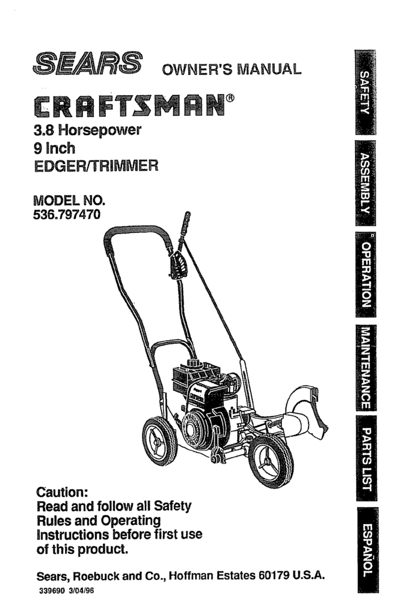
Craftsman 536.797470 User manual

Craftsman

Craftsman 536.797470 User manual

Craftsman 247.772460 User manual

Craftsman

Craftsman 247.772460 User manual

Craftsman 247.772461 User manual

Craftsman

Craftsman 247.772461 User manual

Craftsman 358.797450 User manual

Craftsman

Craftsman 358.797450 User manual

Craftsman CMEED400 User manual

Craftsman

Craftsman CMEED400 User manual

Craftsman 316.773800 Operator's User manual

Craftsman

Craftsman 316.773800 Operator's User manual

Craftsman EDGER 536.7974 User manual

Craftsman

Craftsman EDGER 536.7974 User manual

Craftsman 536.772300 User manual

Craftsman

Craftsman 536.772300 User manual

Craftsman 536.772350 User manual

Craftsman

Craftsman 536.772350 User manual

Craftsman 247.762460 User manual

Craftsman

Craftsman 247.762460 User manual

Craftsman 989.799310 User manual

Craftsman

Craftsman 989.799310 User manual

Craftsman 77236100N - 5.0 Ft-Lbs Gross Torque Edger User manual

Craftsman

Craftsman 77236100N - 5.0 Ft-Lbs Gross Torque Edger User manual

Craftsman EZ.Edge.n.Store 71.79653 User manual

Craftsman

Craftsman EZ.Edge.n.Store 71.79653 User manual

Craftsman 79653 - 12 Amp Edger User manual

Craftsman

Craftsman 79653 - 12 Amp Edger User manual

Craftsman 358.796520 User manual

Craftsman

Craftsman 358.796520 User manual

Craftsman 358.796170 User manual

Craftsman

Craftsman 358.796170 User manual

Craftsman Weedwacker 358.791051 User manual

Craftsman

Craftsman Weedwacker 358.791051 User manual

Craftsman 536.772330 User manual

Craftsman

Craftsman 536.772330 User manual

Craftsman 536.772341 User manual

Craftsman

Craftsman 536.772341 User manual

Craftsman 358.773110 User manual

Craftsman

Craftsman 358.773110 User manual

Popular Edger manuals by other brands

Ryobi EXPAND-IT RYEDG12VNM Operator's manual

Ryobi

Ryobi EXPAND-IT RYEDG12VNM Operator's manual

VEVOR ASYTM02230 manual

VEVOR

VEVOR ASYTM02230 manual

CRL SM5C user manual

CRL

CRL SM5C user manual

Kunzle & Tasin SILVER BACK Instruction handbook

Kunzle & Tasin

Kunzle & Tasin SILVER BACK Instruction handbook

Husqvarna LE475 Operator's manual

Husqvarna

Husqvarna LE475 Operator's manual

Ryobi RED1220 Original instructions

Ryobi

Ryobi RED1220 Original instructions

Echo PE-230 Operator's manual

Echo

Echo PE-230 Operator's manual

Echo PAS-260 PRO - PARTS CATALOG SERIAL NUMBER... parts catalog

Echo

Echo PAS-260 PRO - PARTS CATALOG SERIAL NUMBER... parts catalog

Echo PE-225 Operator's manual

Echo

Echo PE-225 Operator's manual

Huvitz HPE-410 user manual

Huvitz

Huvitz HPE-410 user manual

Zenoah HEZ2610F Other

Zenoah

Zenoah HEZ2610F Other

MTD 244-595-000 owner's manual

MTD

MTD 244-595-000 owner's manual

National Optronics Horizon II instruction manual

National Optronics

National Optronics Horizon II instruction manual

Husqvarna 426EX Operator's manual

Husqvarna

Husqvarna 426EX Operator's manual

luxvision HE-1000 user manual

luxvision

luxvision HE-1000 user manual

Little Wonder Xtra Operator owner's manual

Little Wonder

Little Wonder Xtra Operator owner's manual

Makita EE2650H instruction manual

Makita

Makita EE2650H instruction manual

Black & Decker GH1000 instruction manual

Black & Decker

Black & Decker GH1000 instruction manual

manuals.online logo
manuals.online logoBrands
  • About & Mission
  • Contact us
  • Privacy Policy
  • Terms and Conditions

Copyright 2025 Manuals.Online. All Rights Reserved.

MODEL NO.
536.797561
Caution:
Read and Follow
All Safety Rules
and Instructions
Before Operating
This Equipment
.................................. i............. _'L'Ul'lLl== _ --
9iNCH =3.0 HORSEPOWER
EDGER/TRIMMER
=Assembly
=Operation
•Customer Responsibilities
° Service and Adjustments
•Repair Parts
SEARS, ROEBUCK AND CO., Hoffman Estates, IL 60179 U.S.A.
i lliH lllllllllli,i,llll,lll _ ,,,,,,, ,,, ,, ,,,,,, i i ,,,llmll
Part No 324779
SAFETY RULES
CAUTION: ALWAYS DISCONNECT SPARK PLUG WIRE AND
PLACE WIRE WHERE IT CANNOT CONTACT SPARK PLUG TO
PREVENT ACCIDENTAL STARTING WHEN SETTING-UP, 'TRANS-
PORTING, ADJUSTING OR MAKING REPAIRS,.
BEFORE USE
e Read the owner's manual carefully Be thor-
oughly familiar with the controls and the proper
use of the edgedtrimmer. Know how to stop the
edger/trimmer and disengage the controls
quickly.
e Do not operate the edger!trimmer without
wearing adequate outer garments. Wear foot-
wear that wilt improve footing on slippery sur-
faces.
®Keep the area of operation clear of all persons,
particularly small children and pets_
= Thoroughly inspect the area where the edger/
trimmer is to be used and remove all foreign
objects.
FUEL SAFETY
e Handle fuel with care; it is highly flammable,.
® Use an approved container.
e Check fuel supply before each use, allowing
space for expansion as the heat of the engine
and/or sun can cause fuel to expand.
e Fill fuel tank outdoors with extreme care. Never
fill fuel tank indoors. Replace fuel tank cap
securely and wipe up spilled fuel,
® Never remove the fuel tank cap or add fuel to a
running or hot engine.
®Never store fuel or edger/trimmer with fuel in
the tank inside a building where fumes may
reach an open flame.
OPERATING SAFETY
Never allow children or young teenagers to
operate the edger/trimmer, Keep them away
while it is operating. Never allow adults to
operate the edger/trimmer without proper ir_-
struction.
oAlways wear safety glasses or eye shields
during operation orwhile performing an adjust-
ment or repairto protectyour eyes from foreign
objects that may be thrown from the edger/
trimrner_
®Do not put hands or feet near or under rotating
parts.
® Exercise extreme caution when operating on
or crossing gravel drives, walks, or roads.. Stay
alert for hidden hazards or traffic.
• Exercise cautiQn to avoid slipping or falling
® Never operate the edgefltrimmer without proper
guards, plates, or other safety protective de-
vices in place.,
• Never operate the edger/trimmer at high trans-
port speeds on sfippery surfaces. Look behind
and use care when backing.
eNever allow bystanders near the edger!trim-
mer,
®Keep children and pets away while operating.
®Never operate the edgerttnmmerwithout good
visibility or light°
e Do not run the engine indoors. The exhaust
fumes are dangerous (containing CARBON
MONOXIDE, an ODORLESS and DEADLY
GAS),.
® Take all possible precautionswhen leaving the
edgerttrimmer unattended. Stop the engine.
e Do not overload the edgerttrimmer capacity by
attempting to edge too deep at too fast a rate.
SAFETY RULES
SAFE STORAGE
o Always refer to the owner's manual storage
section for important details if the edger/trim-
mer is to be stored for an extended period.
• Never leave the edger/trimmer with fuel in the
fuel tank inside abuilding where ignition sources
are present such as water and space heaters,
clothes dryers, andthe like+.Allow the engine to
cool before placing in any enclosure_
® Keep the edger/trimmer in safe working condi-
tion+ Check all fasteners at frequent intervals
for proper tightness,.
® Stop the blade whenever you leave the operat-
ing position. Also, stop the engine and discon-
nect the spark plug wire before unclogging the
blade and when making any repairs, adjust-
ments, or inspections.
eWhen cleaning, repairing, or inspecting, shut-
off the engine and make certain all moving
parts have stopped+
a Never attempt to make any adjustments while
the engine is running (except when specifically
recommended by the manufacturer)..
REPAIRIADJUSTMENTS SAFETY
® After striking a foreign object, stop the engine
(motor). Remove the wire from the spark plug,
and keep the wire away from the plug to
prevent accidental starting. Thoroughly inspect
the edger/trimmer for any damage, and repair
the damage before restarting and operating
the edgedtrimmer..
® If the edger/trimmer should start to vibrate
abnormally, stop the engine (motor) and check
immediately for the cause+ Vibration is gener-
ally a warning of troubieo
i iii ii i i iiil.+ i i iiii iii iii i ii,lml,,ll,ulli
I
A LOOK FOR THIS SYMBOL TO POINT OUT
,_j_ IMPORTANT SAFETY PRECAUTIONS. IT I
MEANS--ATTENTION!!! BECOME ALERT!!!_i
3
CONGRATULATIONS on your purchase of a Sears
Craftsman Edger/Trimmer. It has been designed, engi-
neered and manufactured to give you the best possible
dependability and performance.
Should you experience any problemyou cannot easity
remedy, please contact your' nearest Sears Service
CentedDepartment. We have competent, well-trained
techniciansand thepropertoolsto service or repairthis
unit.
Please read and reta{nthis manual. The instructions will
enable you to assemble and maintain your edger/trim-
mer properly. Always observe the.,SAFETY RUL.ES."
MODEL
NUMBER 536.797561
SERIAL
NUMBER
DATE OF
PURCHASE
THE MODEL AND SERIAL NUMBERS WILL BE
FOUND ON A DECAL ON THE FRAME OF THE
EDGER/TRIMMER BEHIND THE ENGtNE_
YOU SHOULD RECORD BOTH SERIAL NUMBER
AND DATE OF PURCHASE AND KEEP IN A SAFE
PLACE FOR FUTURE REFERENCE°
PRODUCT SPECIFICATIONS
.... i / i1' I filL" ......... ".............
HORSEPOWER: 3.0 hp
DISPLACEMENT: 9.06 cu. in.
(148 c.c)
GASOLINE CAPACITY: 1.0 qt.
Unleaded
(Regular)
LUBRICATION: 21 oz.
SAE 30
SPARK PLUG :............. ....... Champion ""
(GAP .030 in.) CJ-8 or
,Equivalent
MAINTENANCE AGREEMENT
ASears Maintenance Agreement is available on this
product,,Contact yournearest Sears Store for=details.
CUSTOMER RESPONSIBILITIES
e Read and observethe safety njleso
e Followa regularschedule in maintaining, caring for and usingyour edger/trimmer,
eFollow the instructions under"Maintenance" and "Storage" sections of thisowner's manual
_:: I/I ,,, iiI It .................... iiiiiiiiiii/ / ......... 11111
TWO YEAR LIMITED WARRANTY ON CRAFTSMAN
EDGER/TRIMMER
Fortwo years from the date ofpurchase, when thisCraftsman Edger/Trimmer is maintained, lubricated
and tuned-upaccordingto the instructionsin theowner's manual, Sears willrepair, free ofcharge, any
defectin materialand workmanship.
Ifthis Craftsman Edger/[rimmer is used forcommercial or rental purposes,this warrantyapplies for only
90 days fromthe date of purchase.
Thiswarranty does not coverthe following:
®Expendable items whichbecome worn duringnormal use, suchas spark plugs,etc=
e Repairs necessary because of operatorabuse or negligence, including bent crankshaftsand the faifure
to maintain the equipmentaccording to the instructionscontained inthe owner's manual
WARRANTY SERVICE IS AVAILABLE BY RETURNING THE CRAFTSMAN EDGER/TRIMMER TO THE
NEAREST SEARS SERVICE CENTER/DEPARTMENT IN THE UNITED STATES THIS WARRANTY
APPLIES ONLY WHILE THIS PRODUCT IS IN USE IN THE UNITED STATES.
This warrantygives you specific legal rights, and you may also have other rights which may vary from
state to state..
SEARS, ROEBUCK AND CO. D/817WA, Sears Tower, Hoffman Estates, tL 60179
4
,_,_,,,,,,,,,_,,_,_,,_, ,i j i ,i , i,u U,lU ................... i ii ,, .................lUlUU
TABLE OCONTE TS....
,_=,,=,,L_,=_,=
SAFETY a_gCES ............................................ 2_3
PRODUCT SPECIFICATIONS ..............................4
CUSTOMER RESPONSIBILITIES ......4, 12-13
WARRANTY .............................................................4
TABLE OF CONTENTS ...................................... 5
ASSEMBLY ...................................................................5-7
OPERATION ................................................. 8-11
SERVICE AND ADJUSTMENTS ...............14-'t 5
TROUBLE SHOOTING ..................................... 16
STORAGE ................................................................ 17
REPAIR PARTS
(EDGER/TRIMMER) ........................................18-20
REPAIR PARTS (ENGINE) ...................... 21-23
PARTS ORDERING/SERVICE .........Back Cover
............ ...................... i ii lU lUll
BLY
.............................. ii u ,u,l,l,lu ii ....................
CONTENTS OF SHIPPING CARTON TOOLS REQUIRED FOR ASSEMBLY
1- 9inchEdgerfrrimmercompletefyassembledexcept
forthe control rod, handles and wheels
1-Control Rod
1 - Owner's Manual (Not Shown)
1 - Parts Bag
1 - Upper Handle Assembly
i - Lower Handle Assembly
3- Wheels
2 - 1/2 inch Wrenches and
2 - 9/t6 inch Wrenches or
2-Adjustable Wrenches
1 - Flatblade Screwdriver
1- Knife
CONTENTS OF PARTS BAG (shown actual size)
2 - 5116-18 x1-114inch
Hex Head Screws
4 - 5/16-18 x 5f8 inch Hex
Head Wide Flange Screws
t'1
li 1-5t16-18 x 3-114inch
Hex Head Screw
@11 -I
1 - 1.39 tnch long Spacer
(front wheel assembly)
I - 3/8-16 x 1,,40 inch
Shoulder Boll
2-Hair Pins
1 - 3t8-16 Hex Head
Wide Flange Locknuls
6 - 5/16-18 Hex Nuts
© i........ill............
1- 1.05 inch long Spacer
(front wheel assembly)
@
1-,70 inch long Spacer
(left rear wheel assembly)
1- Cotter Pin
@
I - 1/2 x 3/4 inch Flatwasher
(right rear wheel assembly)
5
Wide Range Locknut _.,..,JJ
2 - 11/32 x 11/16 Inch
Flatwashers
(front wheet assembly)
u, uu i ul ii .................
1.5/16-18
:: HIIIIIIIIIIII III II II I'll I I _I . I: ............................ '1 ' ---. "Irl"/' ..... .......... : IIII I LI
ASS LY
1' I III L IIILIIIlll I ":........... : III IIIIIIIIIII IIII " .......................
III ' III II I'I" ::: .......................... :Q
CAUTION: ALWAYS WEAR SAFETY
GLASSES OR EYE SHIELDS WHILE
ASSEMBLING EDGER!TRIMMER.
:: ........... ........... :: :
Figure I shows the edger/trimmer completely
assembled
Reference to the right and left hand side of the edger/
trimmer is from the operator's positionbehind the unit..
TO REMOVE EDGER/TRIMMER FROM
CARTON
® Remove the lower'handle fromthe carton.
e Remove the control rod from the carton
® Remove upper handle and packing material from
the carton.
Remove wheels, parts bag and packing material
fromtile carton
Cut down all fourcorners of the carton_
IJLIIIII I I I IIIII ...........................
CLUTCH LEVER
UPPER
HANDLE '_......, CONTROL ROD
STARTER
HANDLE
LOWER
HANDLE
BLADE
GUARD
BLADE
FIG. 1
TO ASSEMBLE THE EDGER/
TRIMMER
NOTE: Lower handle should be attached first as it is
difficult to attach lowerhandle with the wheels on
®Place the lower handle inside the edger/trimmer
frame (See Fig_3A) and secure inplace with four(4)
5/16-!8 x5/8 inch hex head wide flangescrews and
four (4) 5/16-18 hex head iocknuts (found in parts
bag)..
o
Attach the right rear wheelto the wheel support rod
of the edger/trimmer (See Fig 2A) with a 1/2 x 3/4
inch flatwasher and cotter pin (found in parts bag)..
Attach the left rear wheel to the edger/trimmer
(See Fig, 2B) witha 3/8-16 x 1A0 inch shoulder
bolt, spacer (_70inchlong)and 3/8-16 wide flange
Iocknut (found in parts bag).
(_) (VIEW FROM RIGHT SIDE)
FLATWASHER
COTTER
PIN
WHEEL
(_) (VIEW FROM
WHEEL _
SHOULDER
_ (VIEW FROM
SPACER
(1,39 INCH LONG)
WHEEL SUPPC)RT ROD
WIDE FLANGE
SPACER LOCi(NUT
Io7OINCHLONG)
5f16-18 HEX WIDE FLANGI
LOCKNUT
SCREWWHEEL" ACER
FLATWASHER (!,,05 !NCH LONG
FIG. 2
Attach the frontwheel to theedger/trimmer (See
Fig.,2C) with a5/16-18 x3-1/2 inch hex head screw,
two (2) 11/32 X 11/16 inch flatwashers, one (t)
spacer (1.05 inch long), one (t) spacer (139 inch
long) and a 5/16-18 hex locknut (found in parts
bag): ......................................
LOWER HANDLE
5116-18 5f16-18
HEX HEAD HF-.XHEAD
LOCKNUTS LOCKNUTS
O
6
5/16-18 X 5f8 INCH
HEX HEAD WIDE
FLANGE SCREWS
IIII I iii I,
FIG, 3A
........... T_ Illlllll II'11' II1!] ! ffll'lJ I I '1 I '1'11' I I ,,,i
ASSI I li LY
ePlace the upper handle on the lower handle as
shown in Fig. 3B. A1ignhotes inthe upper handle
with the top set of holes in the lower handle and
secure in place with two (2) 5/16-18 x t-1/2 inch
hex head screws and two (2) 5/16-18 hex head
Iocknuts(found in parts bag)
NOTE: Clutch lever ison the left hand side of the upper
handle when properly instatted_
LEVER
FIG, 3B
• Insert one end ofthe control rod from leftto right
through the hole inthe clutch fever(See Fig 4)and
attach with a hair pin (found in the parts bag)
oPlace the clutch lever inthe first depth selection
(See Fig. 4) and insertthe other end oi the con-
trol rod through the hole inthe quill support arm
(See Fig. 4) Attach with hairpin (found inparts bag)
•Move the clutch lever to the rearmost (NEUTRAL)
position and latch in See note below
NOTE: if it is difficult to get the clutch lever into
NEUTRAL, itmay be necessary toloosen the four screws
and nuts holding the lower handle to the frame (See Fig
5)..Pry up (forward) on the handle only enough to allow
the clutch lever to freely enter the NEUTRAL position..
Retighten nuts and screws. When the clutch lever is in
NEUTRAL the Quill Support Arm should be within 1/4
inch of the spacer and screw behind it (See Fig 4 inset)
HAIR PIN
CLUTCH
LEVER
FIRST DEPTH
SELECTION CONTROL
ROD
HAIR PIN
QUILL
SUPPORT
ARM
SPACER
Fig. 4 inset
FIG. 4
QUILL SUPPORT
ARM
LOWER HANDLE
MOUNTING BOLTS
VIEW FROM RIGHT SIDE OF UNIT
FIG, 5
7
KNOW YOUR EDGER/TRIMMER
READ THIS OWNER'S MANUAL AND SAFETY RULES BEFORE OPERATING YOUR EDGER/
TRIMMER, Compare the iUustrationswith youredgerttrimmerto familiarizeyourselfwitt_the locationof various
controlsand adjustments,. Save this manualfor future reference
CLUTCH LEVER
ROD
FUEL FILL
CAP
MUFFLER
INDEX LEVER
BLADE
STARTER
REAR WHE!
THROTTLE CONTR(
REAR VIEW OF ENGINE
OIL FILL
CAP
ADJUSTABLE
FRONT WHEEL
FIG, 6
BLADE
GUARD
THROTTLE CONTROL - Used to control the engine
speed,
CHOKE CONTROL - Used to start the engine
STARTER HANDLE - The engine on this edger/trimmer
is equipped with an easy pull recoi1starter
CLUTCH LEVER - Used to start and stop theblade and
control the depth of cut.
INDEX LEVER - Permits adjustment from the edging
(vertical) positionto trimming (horizontal) position To
change position, pull the indexlever and rotatethe quill
assembly to the desired angle or position
BLADE GUARD - Used toprevent stones or other mate-
rial from being thrownat the operator.
ADJUSTABLE FRONT WHEEL - Front wheel is adjust-
able from side-to-side for balance..Also, can be adjusted
down for curb-hopping (to level edgedtrimmer when
edging along a curb),.
ADJUSTABLE REAR WHEEL - Right rear wheel is
adjustable forcurb-hopping (to leveledger/trimmer when
edging along a curb)..
.......................... . i iiiiii i iiii i , i 1,171 .........
OPE 0
..........................i .......".':'T". "' ,.,,, _,,_L
The operation o!this edger/trimmer Canresult in foreignobjects being thrown intothe
eyes, which can result in severe eye damager Always wear safety glasses or eye
shields while operating the edger/trimmer,
We recommend standard safety glasses or Wide Vision Safety Mask for over your
glasses
CAUTION: KEEP AWAY FROM THE RO-
TATING BLADE. THE BLADE CAN CAUSE
INJURY.
FILL/ADD OIL:
The engine on this edger/trimmer was shipped with little
or no oil. Add oil before you start the engine. Place the
edger/trimmer on a level surface. Remove the oil fill cap
(See Fig 8). Fill the engine crankcase to point of over-
flowing using about 21 ounces (1-1/4 pts) of Sears SAE
10W-30 motor oil or equivalent Reinstall the oil fillcap..
FILL GAS:
CAUTION: GASOLINE IS FLAMMABLE
AND CAUTION MUST BE USED WHEN
HANDLING OR STORING IT. DO NOT
FILL FUEL "I'ANK WHILE EDGER/TRIMMER IS
RUNN1NG_HOT, OR WHEN EDGER/TRIMMER IS
tN AN ENCLOSED AREA. KEEP AWAY FROM
OPEN FLAME, ELECTRICAL SPARK, AND DO
NOT SMOKE WHILE FILLING THE FUEL TANK.
NEVER FILL FUEL TANK COMPLETELY; BUT
FILL THE TANK TO WITHIN 1/4 -1/2 INCH FROM
THETOPTO PROVIDE SPACE FOR EXPANSION
OFFUEL°ALWAYS FILL FUELTANK OUTDOORS
AND USE A FUNNEL OR SPOUT TO PREVENT
SPtLLING_ MAKE SURE TO WIPE UP ANY
SPILLED FUEL BEFORE STARTING THE EN-
GINE.
STORE GASOLINE IN A CLEAN, APPROVED
CONTAINER_ AND KEEP THE CAP IN PLACE ON
THE CONTAINER. KEEP GASOLINE IN A COOL,
WELL VENTILATED PLACE; NEVER IN THE
HOUSE. NEVER BUY MORE THAN A 30 DAY
SUPPLY OF GASOLINE 70 ASSURE VOLATIL-
ITY°GASOLINE IS INTENDED TO BEUSED AS A
FUEL FOR INTERNAL COMBUSTION ENGINES;
THEREFORE, DO NOT USEGASOLINE FOR ANY
OTHER PURPOSE. SINCE MANYCHILDREN LIKE
THE SMELL OF GASOLINE, KEEP IT OUT OF
THEIR REACH BECAUSE THE FUMES ARE
DANGEROUS TO INHALE, AS WELL AS BEING
EXPLOSIVE.
........................................ i ,,
Fill thefuel tank (See Fig_7) with clean, fresh, unleaded
grade automotive gasoline. Be sure that the container
you pour the gasoline fromis clean and freefrom dust or
other foreign particles Never use gasoline that may be
stale from long pedods of storage in the container
Never use engine or carburetor cleaner products in the
fuel tank or permanent damage may occur You may use
a gasoline stabilizer for extended storage (see the En-
gine Storage paragraph in the Storage section of this
manual).
JUI J L
FUEL FILL CAP
OIL FILL CAP
FIG. 7
|
CAUTION: NEVER FILL THE GAS TANK I
WHILE'THE ENGINE IS RUNNING ORHOT. I
IMMEDIATELY WIPE OFF ANY SPILLED I
GASOLINE BEFORE ATTEMPTING TO
START THE ENGINE_ I
Ill I L'_I _ / II I IIIIIIIlU"I I I I I II IIII Ill' H _lln' i,iiiii "".
O RAT
........................ i illll,,,,,meul .......................
PRE-USE CHECK OF CONTROLS o When the engine starts, move the choke control to
the OFF speed position To increase the engine
Allcontrols should be checked for proper function before
servicing or starting the engine
eMove the clutch lever to all six (6) positions inthe
selector plate, Make surethe clutch leversnaps into
all six (6) holes (See Fig 6).
e Move the index lever to afisix notches in the index
plate (See Fig..6)..
•Return the clutch lever to the rearmost hole in the
selector plate and return the index lever' to the
vertical (deeper notch) position
speed, push the throttle control lever' up. To de-
crease the engine speed pull the throttle control
down
NOTE: The cutting blade speed is controlled by the
engine speed..To reducethe cutting blade speed, push
down on the throttle control lever..To increase the blade
speed, push up on the throttle control lever..
To stop the engine, make sure the clutch lever is all
•the way back (or'up) and move the throttle control
lever to the STOP position.
TO START THE ENGINE
Before starting the engine, be sure you have read and
understood allthe instructionsonthepreceding pages The
edger/trimmer is equipped with a recoil starter. The
operation of the engine is controlled by the throttle and
choke control levels
oPull the clutch lever all the way back (or up) to the
rearmosthole to raise and disengage the blade.
oMove the throttle control lever (See Fig. 6) tothe
RUN position..
oMove the choke control lever (See Fig 6) to the
FULL choke postion.
NOTE: A warm engine should not need to be choked
•To start engine, grasp the starter handle firmlywith
your right hand.
eHold the upper handle firmly with your left hand
e PulIup sharply onthe recoilstarter handie DONOT
allow the starter rope to snap back, let it rewind
slowly while holding the starter handle.
NOTE: Itwilltake a few pulls on the starter handle tofeed
gas from the fueltank to the carburetor
CAUTION: NEVER RUN THE ENGINE IN-
DOORS OR IN A POORLY VENTILATED
AREA. ENGINE EXHAUST CONTAINS
CARBON MONOXIDE, AN ODORLESS
GAS AND DEADLY GAS.
KEEP HANDS, FEET, HAIR AND LOOSE
CLOTHING AWAY FROM ANY MOVING
PARTS ON THE ENGINE OR EDGER!
TRIMMER.
WARNING - AVOID THE MUFFLER AND
SURROUNDING AREAS (SEE FIGo 6),
TEMPERATURES MAY EXCEED 150° F.
i• _1 ll,ll=,ll= m
CAUTION: NEVER LEAVE THE EDGER/
TRIMMER UNATTENDED WHILE _,HE EN-
GINE ISRUNNING. ALWAYS DISENGAGE
THE CUTTING BLADE AND STOP THE
ENGINE,
..... : :I I II IIII IIII u ii II
EDGING OPERATION
eStart theengine and move the clutch lever forward
(or down) to engage the cutting blade
eSelect the edging depth you need There are 5
selections up to 2-3/4 inchesdeep
IMPORTANT: IFVERY DEEP EDGINGIS REQUIRED,
WERECOMMEND THATA SHALLOW
CUT BE MADE FIRST, THEN CUTS
AT GREATER DEPTHS UNTIL THE
DESIRED DEPTH IS OBTAINED..
TRIMMING OPERATION
Stop the engine and disconnect the spark plug wire
from the spark plug
Loosen theteeknob (See Fig, 8) on the front wheel
arm and slidethe wheel all theway tothe rightside
eTighten the tee knob securely.,
CAUTION: THE FRONT WHEEL MUST BE
IN TIlE EXTREME RIGHT POSITION TO
PREVENT THE BLADE FROM STRIKING
WHEEL WHILE IN TRIMMING POSITION.
TEE KNOB
FRONT WHEEL SHOWN ALL THE WAY TO THE RIGHT
FIG. 8
t0