ESTEC LM 128P User manual
LM
128P
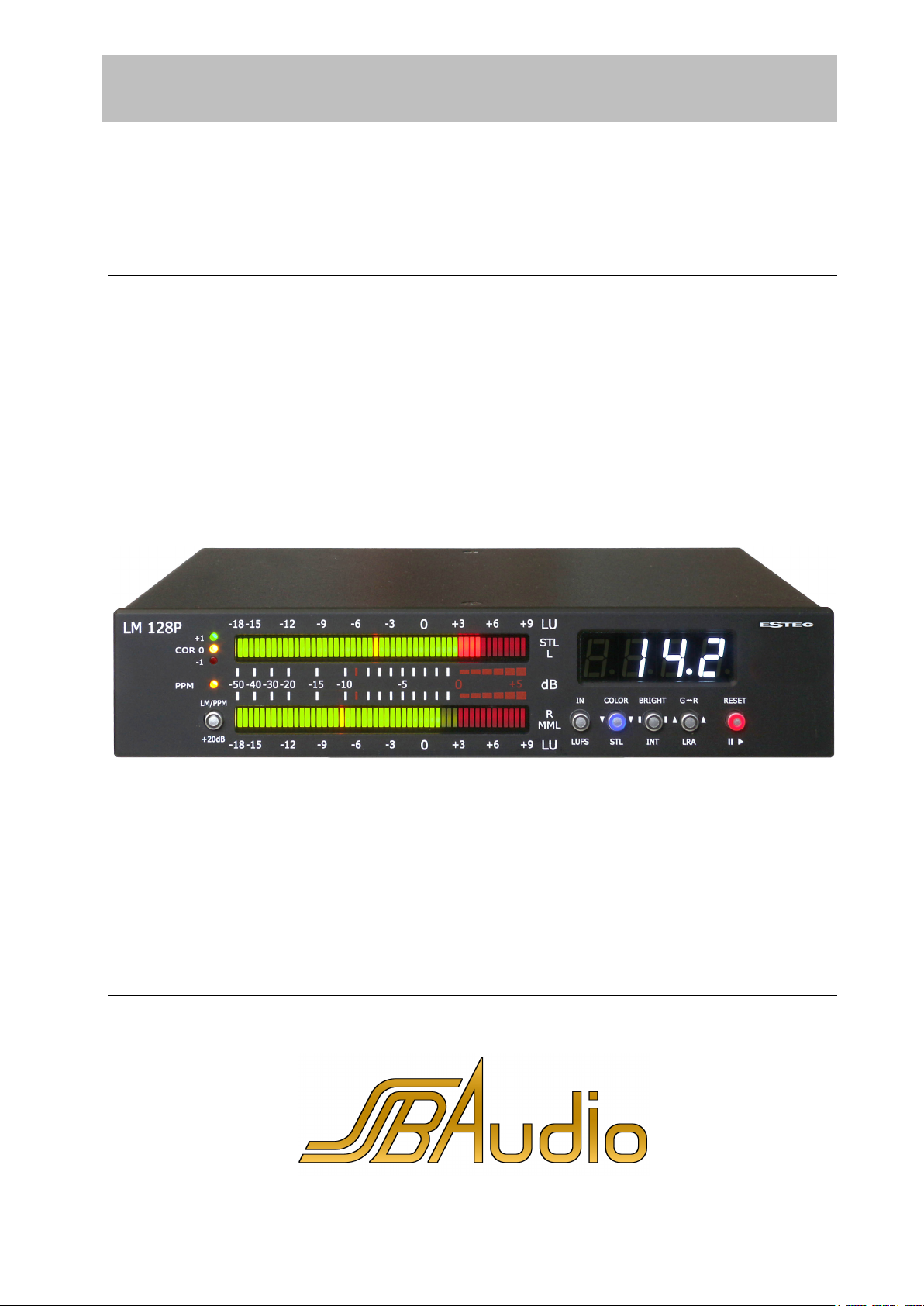
Loudness and Peak Program Meter according to EBU R 128
SSB AUDIO GmbH * Sonnenweg 25 * 30827 Garbsen, Germany
Tel.: +49 5131 464272
www.ssb-audio.com * info@ssb-audio.com
Firmware Version P4.0x
Installation
Operation
www.ssb-audio.com

LM
128P
Loudness and Peak Program Meter according to EBU R 128
2
SSB AUDIO GmbH * Sonnenweg 25 * 30827 Garbsen, Germany
Tel.: +49 5131 464272 * www.ssb-audio.com * info@ssb-audio.com
Content
1 Safety guidelines – read before using! .................................................................... 3
2 Properties ........................................................................................................... 4
2.1 Inputs .......................................................................................................... 4
2.2 Display ........................................................................................................ 4
2.2.1 LU Display Mode ..................................................................................... 4
2.2.2 PPM Display Mode ................................................................................... 4
2.2.3 Common in both Display Modes ................................................................ 4
2.3 Keys ............................................................................................................ 5
3 Technical Data ..................................................................................................... 5
4 Connections ........................................................................................................ 5
4.1 Power Supply ................................................................................................ 5
4.2 Digital Audio Inputs ....................................................................................... 5
4.2.1 AES Input .............................................................................................. 5
4.2.2 3G-SDI Input/Output (optional) ................................................................ 6
4.2.3 Sample Rates ......................................................................................... 6
4.3 Analog Inputs (optional) ................................................................................ 6
4.4 Remote Control ............................................................................................. 6
4.4.1 Connection ............................................................................................. 6
4.4.2 Function ................................................................................................. 6
4.5 USB Connector .............................................................................................. 6
5 Operation ........................................................................................................... 6
5.1 LED Bars ...................................................................................................... 6
5.1.1 LM Display Mode ..................................................................................... 7
5.1.2 PPM Display Mode ................................................................................... 7
5.2 Correlation Display ........................................................................................ 7
5.2.1 Missing Audio Signal Indication ................................................................. 7
5.3 Numerical 7-Segment Display ......................................................................... 7
5.3.1 Switching the Numerical Display On or Off ................................................. 7
5.3.2 Clip Indication ........................................................................................ 8
5.4 Input Selection AES, SDI and Analog ............................................................... 8
5.5 Start, Stop, Pause INT and LRA ....................................................................... 8
5.6 Display Options ............................................................................................. 8
5.7 Reference Level Settings and Clip Indication Time ........................................... 10
5.7.1 LU Reference Level ................................................................................ 10
5.7.2 ADC Full-Scale dBu-Level ....................................................................... 10
5.7.3 PPM Reference Level .............................................................................. 10
5.7.4 Clip Indication Time ............................................................................... 10
5.8 More Displays ............................................................................................. 11
5.8.1 Version Number .................................................................................... 11
5.8.2 Sample Rate ......................................................................................... 11
5.9 Factory Defaults .......................................................................................... 11
5.9.1 Factory Defaults for Loudness Meter (LM) ................................................. 11

LM
128P
Loudness and Peak Program Meter according to EBU R 128
3
SSB AUDIO GmbH * Sonnenweg 25 * 30827 Garbsen, Germany
Tel.: +49 5131 464272 * www.ssb-audio.com * info@ssb-audio.com
5.9.2 Factory Defaults for Peak Program Meter (PPM) ........................................ 12
6 Control Functions Overview ................................................................................. 12
6.1 Short Keystroke .......................................................................................... 12
6.2 Long Keystroke ........................................................................................... 12
6.3 Settings ..................................................................................................... 13
6.3.1 Inputs.................................................................................................. 13
6.3.2 Color Scheme ....................................................................................... 13
6.3.3 Brightness ............................................................................................ 13
6.3.4 LED bar Yellow Tint (G◄─►R) ................................................................. 13
6.4 Reference Level Settings and Clip Indication Time ........................................... 14
6.4.1 LU Reference Level ................................................................................ 14
6.4.2 ADC Full-Scale dBu-Level (if analog inputs are available) ........................... 14
6.4.3 Clip Indication Time ............................................................................... 14
7 USB Functions ................................................................................................... 15
8 Appendix .......................................................................................................... 16
1 Safety guidelines – read before using!
The device meets protection class 2 and has left the factory in a technically faultless state.
In order to assure this state and to insure riskless operation the user must obey the notes and warnings which are
part of this manual.
Safety, reliability and performance of this device are guaranteed only when:
Installation, expansions, modifications and repairs are accomplished only by the manufacturer or by personal
authorized by the manufacturer.
The electrical installations of the relevant room meet the corresponding IEC (ANSI) requirements.
The device is used in accordance with this user manual.
Power supply
The device is designed for continuous operation. The power supply’s operating voltage must meet the local line
voltage.
Avoid connections to the power supply system in junction boxes together with many other devices. The electrical
outlet needs to be installed close to the device and easily accessible.
Use the supplied power supply unit. Other power supplies may cause malfunctions or even damage the device.
Installation site
The device should stand only on clean horizontal work surfaces or be installed in a suitable rack. During operation
the device must not be exposed to vibration. Humidity, liquids of all kinds and dust must be kept away as far as
possible. Sufficient ventilation needs to be provided. Avoid direct sunshine and the proximity of radiators and
radiant heaters.

LM
128P
Loudness and Peak Program Meter according to EBU R 128
4
SSB AUDIO GmbH * Sonnenweg 25 * 30827 Garbsen, Germany
Tel.: +49 5131 464272 * www.ssb-audio.com * info@ssb-audio.com
2 Properties
The Estec LM 128P is a Loudness and PPM Meter according to the EBU-recommendation R 128. It fulfills the
demands for the ‘EBU Mode’ corresponding to the specifications
EBU R 128 (September 2011),
ITU-R BS.1770-2 (March 2011),
EBU Tech Doc 3341 (August 2011)
EBU Tech Doc 3342 (August 2011) and
DIN IEC 60268-10
For more information please refer to http://tech.ebu.ch/loudness .
Note: The LM 128P does not incorporate a true peak meter according to EBU R 128.
2.1 Inputs
1 AES/EBU digital input (XLR) for measurements of stereo signals
Option: 3G-SDI input/output (BNC) carrying up to 4 stereo signals, each of which can be selected to be
measured
Option: 2 analog inputs (2 x XLR, stereo)
2.2 Display
2.2.1 LU Display Mode
Short Term Level (average value over 3000 ms) with tricolor LED
bar with 51 segments
Momentary Loudness (average value over 400 ms) with tricolor LED
bar with 51 segments
2.2.2 PPM Display Mode
2 tricolor LED bars with 51 segments displaying the left and the right channel’s PPM values
Scale range from -50 dB to +6 dB, linear from -10 dB to +6 dB with 2 LEDs per dB
2.2.3 Common in both Display Modes
Numerical display of Short Term Loudness, Integrated Loudness or Loudness Range by
a four-digit 7-segment display
Numerical display of Momentary Loudness and Integrated Loudness selectable between
LU and LUFS
3 LEDs +1, 0 and –1 to display L/R-correlation in 5 ranges
Various options for individual display and operation settings
LM
128P
Loudness and Peak Program Meter according to EBU R 128
5
SSB AUDIO GmbH * Sonnenweg 25 * 30827 Garbsen, Germany
Tel.: +49 5131 464272 * www.ssb-audio.com * info@ssb-audio.com
2.3 Keys
Key +20dB: Adds 20 dB gain to the PPM display. Also: Selection between Loudness Meter (LM) Display
Mode and Peak Program Meter (PPM) Display Mode.
Key LUFS: Selection between LU (relative to a reference level) and LUFS (absolute to full scale level).
Also: Selection between AES/EBU, SDI and analog inputs (if available).
Keys STL, INT and LRA: Selection of the 7-segment display: Short Term Loudness,
Integrated Loudness or Loudness Range. Also: Setup functions.
Keys RUN/PAUSE resp. RESET: Start, Stop resp. Pause as well as resetting the Integrated Loudness
and the Loudness Range measurement.
3 Technical Data
1 AES/EBU input, XLR, transformer coupled, for stereo signal measurements
Optional 3G-SDI input/output, 2 x BNC
Optional balanced analog inputs, input impedance approx. 34 kOhm, reference level for 0 LUFS adjustable
from 0 dBu up to +24 dBu in steps of 1 dB
15 sample rates (8 kS/s up to 96 kS/s) are recognized automatically
Automatic filter coefficients adjustment for 1 kHz reference frequency
Sliding 400 ms and 3000 ms measuring windows with 25 ms resolution (i. e., the update rate is 40 Hz and
the overlapping is 375 ms and 2975 ms resp.)
PPM measurements with 10 ms/90% resp. 5 ms/80% attack and 1.5 s/-20 dB decay time
Correlation Meter dynamic range > 130 dB
5 V low voltage supply, max. 2 A
Size (W x H x D): 190 mm x 40 mm x 140 mm
Weight: 850 g without / 900 g with optional SDI and analog inputs
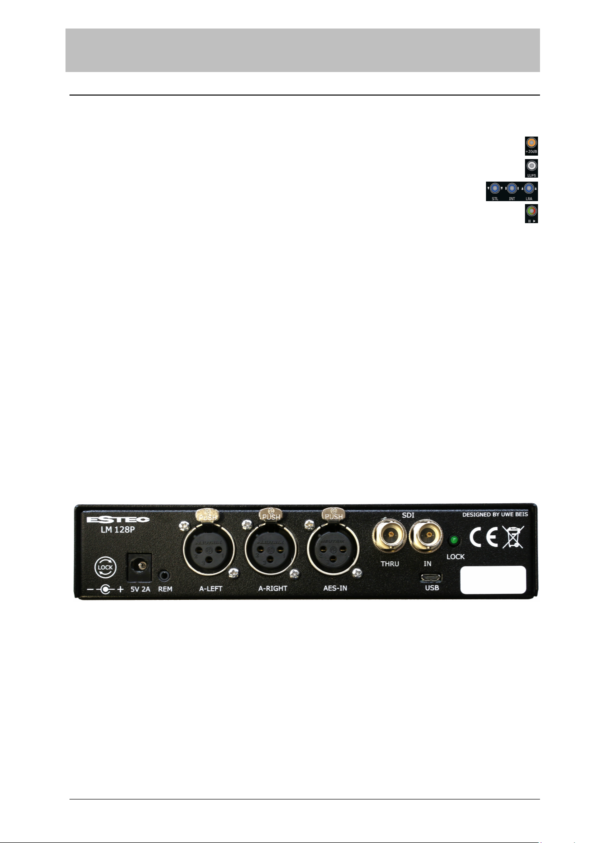
4 Connections
4.1 Power Supply
5 V DC: Please use the supplied power supply unit. Other power supplies may cause malfunctions or even damage
the device.
4.2 Digital Audio Inputs
4.2.1 AES Input
This is an AES/EBU resp. AES3 input. With a matching adapter also AES3id (BNC) or S/P-DIF (RCA) signals can be
applied.
LM
128P
Loudness and Peak Program Meter according to EBU R 128
6
SSB AUDIO GmbH * Sonnenweg 25 * 30827 Garbsen, Germany
Tel.: +49 5131 464272 * www.ssb-audio.com * info@ssb-audio.com
4.2.2 3G-SDI Input/Output (optional)
The optional 3G-SDI input/output provides a 4 stereo channel audio de-embedder for data stream 1. These 4
stereo signal pairs can be selected to be measured. The green LED “LOCK” will be on when a valid SDI signal is
detected.
4.2.3 Sample Rates
The LM 128P operates with the following 15 sample rates where the filter coefficients are automatically chosen
correctly for 1 kHz reference frequency:
8, 11.025, 12, 16, 22.05, 24, 32, 44.1, 48, 64, 88.2 and 96 kHz
For all other sample rates the filter coefficients of the closest known frequencies are chosen.
4.3 Analog Inputs (optional)
An optional analog stereo input is available on two XLR jacks.
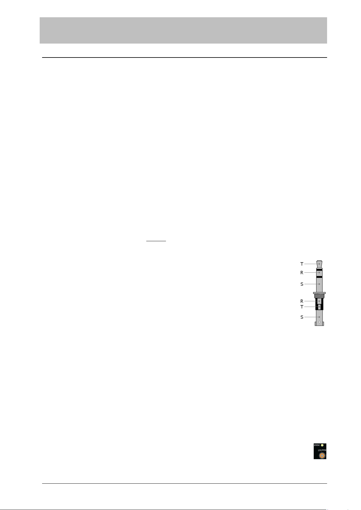
4.4 Remote Control
The LM 128P is equipped with a remote control input with a 3-pin TRS (Tip, Ring, Sleeve) jack. With external keys
it is possible to
- start, stop and reset the INT and LRA measurement,
- select between STL, INT and LRA for the numerical display and
- clear the clipping indication.
Attention: The plug needs to be plugged strongly as far as it will go into the jack!
4.4.1 Connection
Two keys switching to ground can be connected.
T (Tip): Start, stop and reset the INT and LRA measurement
R (Ring): Select between STL, INT and LRA for the numerical display and clear clipping indication
S (Sleeve): Ground
4.4.2 Function
A key at pin T operates identically to the RUN/PAUSE resp. RESET key at the LM 128P.
With a key at pin R the numerical display is cyclically switched between STL, INT and LRA. The blue
LEDs in the corresponding keys display the current selection.
Pressing the key at pin R for a longer time will clear the clipping indication.
4.5 USB Connector
The LM 128P is equipped with a USB connector in order to read out the measured loudness values and to control
the most important functions. Refer to Chapter 7 “USB Functions”.
5 Operation
5.1 LED Bars
Depending on the display mode the LED bars either show LM (Loudness Meter) values or PPM (Peak Program
Meter) values.
Selection between both modes is done by pressing the LM/PPM key a long time (longer than 800 ms). The
display mode is indicated by the yellow LED PPM above the key, beside the PPM scale.

LM
128P
Loudness and Peak Program Meter according to EBU R 128
7
SSB AUDIO GmbH * Sonnenweg 25 * 30827 Garbsen, Germany
Tel.: +49 5131 464272 * www.ssb-audio.com * info@ssb-audio.com
5.1.1 LM Display Mode
After power-on in LM display mode the upper LED bar SHORT TERM LEVEL (STL) shows the input’s signal
average power integrated over the recent 3000 ms. The lower LED bar MOMENTARY LEVEL (MML) shows the
input’s signal average power integrated over the recent 400 ms.
The marker 0 LU refers to the target loudness level which
should be set to -23 LUFS in order to comply with the EBU R
128 ‘EBU Mode’ specifications. It can be adjusted. In case the LU reference level is not set to -23 LUFS the
LM 128P does not operate in the ‘EBU Mode’.
5.1.2 PPM Display Mode
In PPM display mode the LED bars display the measured PPM
values for the left resp. the right channel. The reference level
for the PPM display is -9 dBFS, i.e., with a digital signal of -9 dBFS a PPM value of 0 dB is displayed.
In the PPM display mode 20 dB gain can be added to the displayed PPM value so that signals down to
even -70 dB can be detected. The additional gain is selected by the key +20dB and indicated by the
illuminated key.
5.2 Correlation Display
The left/right channel correlation factor is displayed from -1 to +1 with 3 LEDs.
With these 3 LEDs 5 ranges of correlation can be discriminated:
+1.0 to
+0.6
+0.6 to
+0.2
+0.2 to
-0.2
-0.2 to
-0.6
-0.6 to
-1.0
5.2.1 Missing Audio Signal Indication
The correlation display is also used to indicate when the digital audio signal is missing. In this case all three LEDs
are flashing synchronously.
5.3 Numerical 7-Segment Display
The numerical display indicates measured loudness values during normal operation and settings in Setup Mode.
During normal operation the display may optionally display:
The Short Term Level value STL,
the Loudness Integrated value INT and
the Loudness Range value LRA.
Selection is done by keys STL, INT and LRA. After power-up the 7-segment display shows the
Short Term Level.
For the values STL and INT, the readout can be selected between LU/LUFS:
For LUFS (Loudness Units Full Scale) the key LUFS is pressed so that it is lit.
For LU (Loudness Units relative) the key LUFS is pressed so that it is not lit. The displayed value is
referenced to the LU reference level mentioned above.
5.3.1 Switching the Numerical Display On or Off
In LM display mode the numerical display and the LEDs in the keys below are always on.
In PPM display mode it can be selected whether the numerical display and the LEDs shall be on or off.
In order to select between display on and off in PPM mode, select PPM mode first.
To turn the display off, press the key with the blue LED on. The display will be switched off.

LM
128P
Loudness and Peak Program Meter according to EBU R 128
8
SSB AUDIO GmbH * Sonnenweg 25 * 30827 Garbsen, Germany
Tel.: +49 5131 464272 * www.ssb-audio.com * info@ssb-audio.com
To turn the display on, press any key under the display. The display will be switched on.
5.3.2 Clip Indication
The numerical display is also used to indicate when the audio signal is clipped, even in PPM display mode when it is
off.
Clipping is defined as three sequential samples with their 16 MSBits to be either = 7FFF (hex) or <= 8001 (hex).
Clipping is indicated by the word ‘CLIP’. Refer to chapter ‘Clip Indication Time’ for display options.
5.4 Input Selection AES, SDI and Analog
Selection between the inputs is done by pressing the key IN for a longer time:
After pressing the IN key for a minimum time of 800 ms the selected input is displayed as soon as the
key is released but it cannot be changed. The middle blue key starts flashing in order to indicate that it now
works as ‘Exit’ ( ▌) key.
After pressing the IN key for a minimum time of 5 s the selected input is displayed and can be
changed. All three blue keys start flashing. This indicates that the three keys now work as ‘Up’
(▲), ‘Down’ (▼) and ‘Exit’ ( ▌) keys.
The selected input is indicated in the numerical display. 0 corresponds to the AES input, 1, 2, 3 and 4 are the SDI
stereo signal pairs and A is the analog input.
AES: Press the key IN a long time (longer than 5 s), then press key ‘Up’ (▲) or ‘Down’ (▼) until ‘In 0’ is visible
in the numerical display and then ‘Exit’ ( ▌).
ADC: When an ADC is installed it is selected by pressing the key IN a long time (longer than 5 s) and afterwards
pressing key ‘Down’ (▼) until ‘In A’ is visible in the numerical display.
SDI: When a 3G-SDI module is installed each of its four outputs is selected by pressing the key IN a long time
(longer than 5 s) and afterwards pressing keys ‘Up’ (▲) or ‘Down’ (▼) until the desired input ‘In 1’ to
‘In 4’ is selected.
5.5 Start, Stop, Pause INT and LRA
Pressing the Pause/Run key shortly starts the INT (Loudness Integrated) and the LRA (Loudness Range)
measurement. Another short push lets them pause, then continue again and so on.
During running measurements the Pause/Run key is lit green. It is lit red when the measurements are paused. It
is lit yellow when the measurements are running but the STL resp. the MOM value is ignored because its level is
below the ‘Absolute Gating Threshold’ of -70 LUFS as defined by the EBU.
After power-up both measurements are reset and stopped (the key is lit red). As long as no valid measured value
is present, ‘----’ is displayed when the INT or LRA value is selected for display. As soon as the measurements
have been started and the level is above -70 LUFS the display shows the corresponding INT or LRA value which has
been evaluated since the start of the measurements.
The measurements can be reset as well while they are running (key is lit green or yellow) as during pause (key is
lit red) by pressing the RESET key for a longer time (minimum 800 ms).
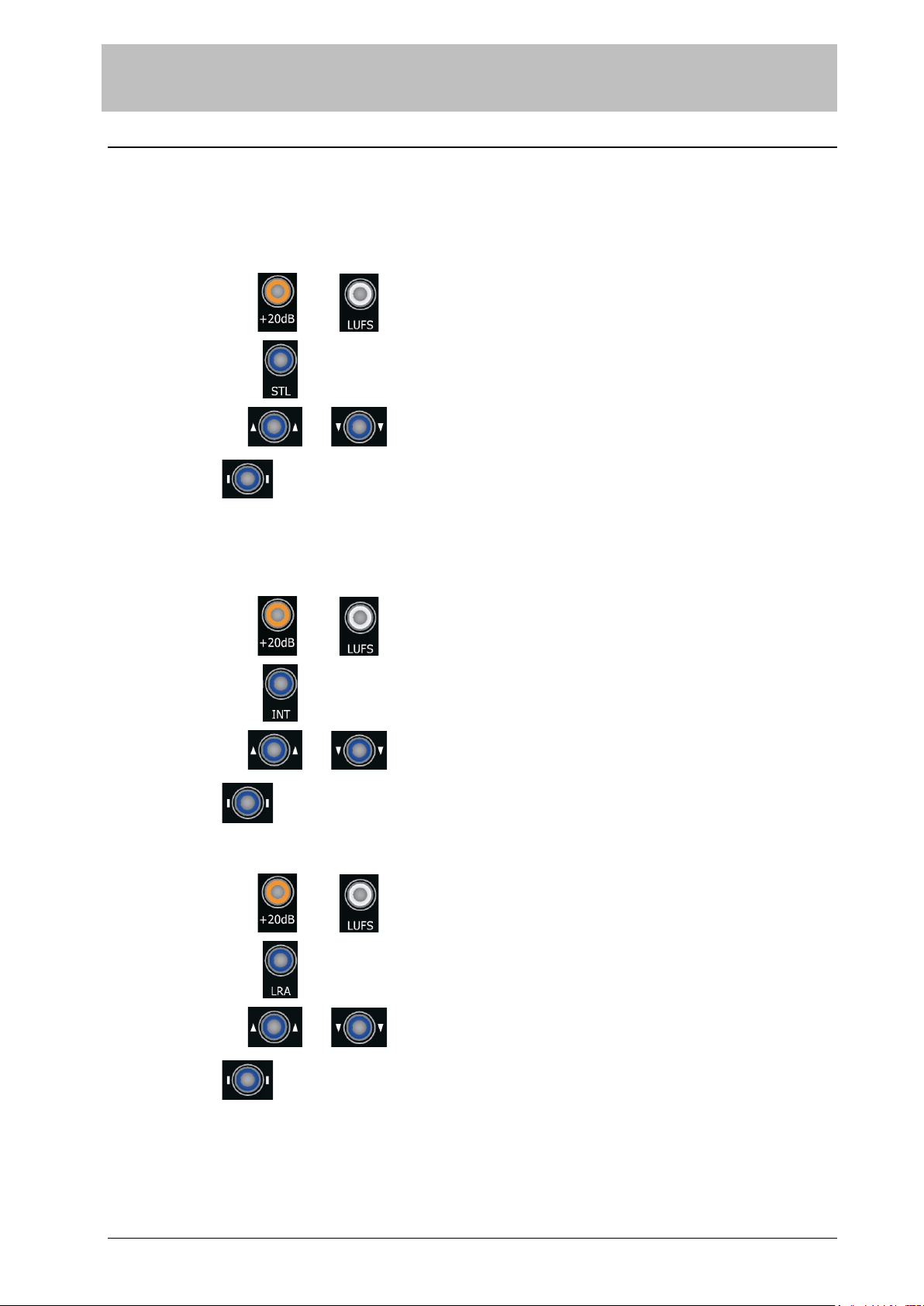
5.6 Display Options
The LM 128P offers display options for
COLOR Scheme,
Brightness (BRIGHT) and
LED bar yellow (G◄─►R)
These three settings are initiated by pressing the desired blue key for a longer time:
After pressing the key for a minimum time of 800 ms the selected setting is displayed as soon
as the key is released but it cannot be changed. The middle blue key starts flashing in order to indicate that it
now works as ‘Exit’ ( ▌) key.
After pressing the key for a minimum time of 5 s the selected setting is displayed and can be changed. All three
blue keys start flashing with the selected key flashing inversely. This indicates that the three keys now work as
‘Up’ (▲), ‘Down’ (▼) and ‘Exit’ ( ▌) keys.

LM
128P
Loudness and Peak Program Meter according to EBU R 128
9
SSB AUDIO GmbH * Sonnenweg 25 * 30827 Garbsen, Germany
Tel.: +49 5131 464272 * www.ssb-audio.com * info@ssb-audio.com
A numerical equivalent of the corresponding setting is indicated by the 7-segment display.
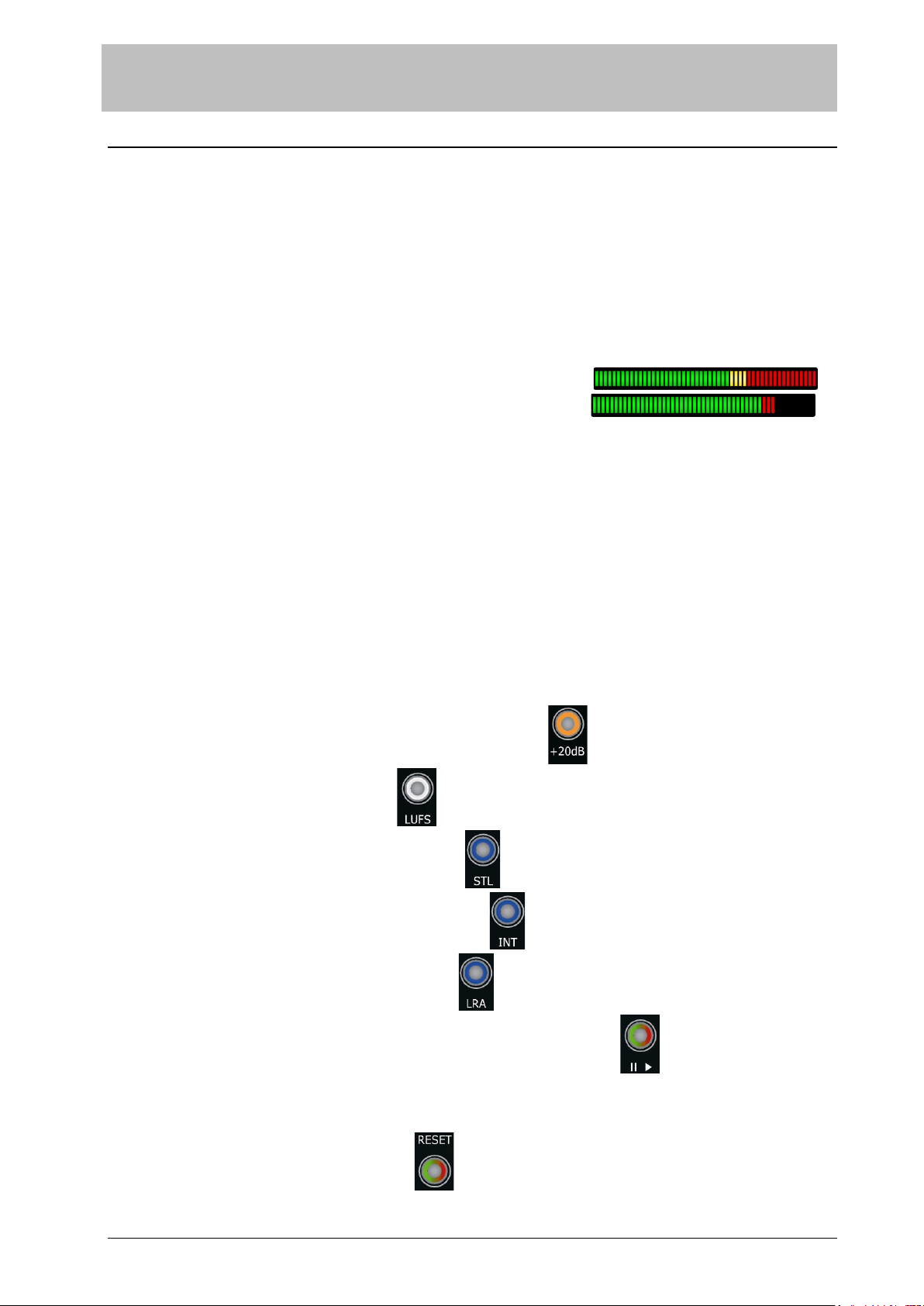
COLOR The user may choose his preferred color pattern for the LED bars and also between bar display and dot
display by selecting color schemes.
With a bar display all LEDs up to the measured value are
lit, all others are adjustable weakly lit or off.
With a dot display all LEDs are adjustably weakly lit or off
while the measured value is indicated by a bright yellow
LED.
Color schemes are different for LU and PPM bars. When the LU display mode is selected, the user can
choose between color schemes provided for the LU Display Mode and when the PPM Display Mode is
selected, the user can choose between color schemes provided for the PPM Display Mode.
Positive numerical values indicate bar display settings while negative values indicate the same color
scheme but as dot display.
These color patterns are available for LU bars:
1
2
3
4
5
6
In the LU display mode the color schemes (color patterns and bar/dot display) of both LED bars can be
chosen individually: At first the color pattern of the upper LED bar is selected for setup. Each time the
COLOR key is pressed again for a minimum time of 800 ms the other LED bar is selected.
These color patterns are available for PPM bars:
0
Combined bar and dot display, read below
1
Red starts at 0 dB
2
Yellow starts at 0 dB
3
Red starts at 0 dB
4
Yellow covers -9 dB to 0 dB
5
Yellow covers -10 dB to 0 dB
6
Yellow/green segments, borders at
-50, -40, -30, -20, -10, -5 and 0 dB
7
With pattern 0 both, the peak program value and the digital peak value are displayed:
Value Peak Program Value Digital Peak Value
EBU aka QPPM SPPM or Fast PPM
Attack Time 10 ms to 90% Zero (one sample)
Decay time 20 dB/1.5s
Displayed by Bar Yellow dot
100% Full scale at +9 dB (out of scale) 0 dB (green/red segment border)
20 dB Gain added optionally Yes No
BRIGHT With this setting the operator can suit the brightness of all displays (LEDs) according to his
preferences.

LM
128P
Loudness and Peak Program Meter according to EBU R 128
10
SSB AUDIO GmbH * Sonnenweg 25 * 30827 Garbsen, Germany
Tel.: +49 5131 464272 * www.ssb-audio.com * info@ssb-audio.com
The background brightness can be adjusted by pressing the BRIGHT key a second time again for a
minimum time of 800 ms.
G◄─►R With this setting the tint of the LEDs set as yellow can be changed between red and green resulting in
further variations for the color schemes. Particularly for color pattern 6, where all LEDs are yellow, the
user may select his preferred monochrome tint for the LED bar between green, different variations of
yellow up to red.
5.7 Reference Level Settings and Clip Indication Time
Attention: For correct measurements the Reference Level Settings must be set correctly. Wrong settings, e.g.
accidentally misadjusted settings, lead to hardly noticeable false measurements!
These three settings are initiated by pressing the LM/PPM key together with the IN key for a
longer time (minimum 800 ms). All three blue keys start flashing. Now the desired setting is
selected by pressing the corresponding blue key for a short time whereby the selected key starts to flash inversely.
The three keys now work as ‘Up’ (▲), ‘Down’ (▼) and ‘Exit’ ( ▌) keys.
5.7.1 LU Reference Level
The LU reference level for the measured LU (Loudness Unit) value can be set between -30 LUFS and 0 LUFS in
steps of 1 LU. According to the EBU R 128 this setting shall be -23 LUFS for the EBU Mode. With a setting other
than -23 LUFS the LM 128P will no longer work in the EBU Mode.
The LU reference level can be changed after pressing the LM/PPM key together with the IN key for a longer time
(minimum 800 ms) followed by pressing the STL/COLOR key shortly. During setup the numerical display shows
the LU reference level as LUFS.
5.7.2 ADC Full-Scale dBu-Level
When the LM 128P is equipped with an ADC the analog input’s gain can be adjusted in 25 steps of 1 dB each so
that the digital full-scale value is between 0 dBu and +24 dBu.
Example: A setting of 18 means that an analog signal of +18 dBu is converted to 100% FS. In other words, a sine
signal of +18 dBu and 1 kHz applied to both inputs L and R results a measured value of 0 LUFS and a
sine signal of +9 dBu is displayed as a peak program value of 0 dB. (This setting corresponds to the
standard reference level of the ITU-R BS.645-2).
Standard settings are:
Recommendation
Full-Scale dBu-Level
Setting
Analog Level
resulting in
Digital 100% FS
Nominal Level resp.
Permitted Maximum Level
0 dB
Alignment Level
–9 dB
ITU-R BS.645-2 18 +18 dBu +9 dBu 0 dBu
ARD HFBL-K 15 +15 dBu +6 dBu -3 dBu
The ADC full-scale dBu-level can be changed after pressing the LM/PPM key together with the IN key for a longer
time (minimum 800 ms) followed by pressing the INT/BRIGHT key shortly. During setup the numerical display
shows the ADC full-scale dBu-level in dBu.
5.7.3 PPM Reference Level
The PPM reference level is fixed according to IEC 268-10/1 so that an input signal of -9 dB FS is displayed at 0 dB
on the PPM scale.
5.7.4 Clip Indication Time
The clip indication time is the time during which the word ‘CLIP’ is displayed in the numerical display after
clipping of a digital audio signal has been detected. It can be set to 0.2 – 0.3 – 0.5 – 0.7 – 1.0 – 1.4 – 2.0 – 3.5 –
7.0 - 10 seconds. It also can be set to ‘ OFF’ which indicates that no clipping is displayed. Additionally it can be
set to infinite (‘ On’). In this case the display must be cleared manually by either of the three blue keys
(STL, INT or LRA).
The clip indication time can be changed after pressing the LM/PPM key together with the IN key for a longer time
(minimum 800 ms) followed by pressing the LRA/G◄─►R key shortly. During setup the numerical display shows
the clip display time in seconds resp. the settings ‘ On’ or ‘ OFF’.

LM
128P
Loudness and Peak Program Meter according to EBU R 128
11
SSB AUDIO GmbH * Sonnenweg 25 * 30827 Garbsen, Germany
Tel.: +49 5131 464272 * www.ssb-audio.com * info@ssb-audio.com
5.8 More Displays
5.8.1 Version Number
The firmware version and revision number, e.g. ‘P4.00’ (version 4, revision 0), is displayed temporarily after the
LM 128P is powered up and visible for a few seconds until the device is operational.
5.8.2 Sample Rate
The sample rate of the selected digital audio input signal is displayed after the LM/PPM key together with the IN
key is pressed for a longer time. In case no signal is present, ‘----’ is displayed. In case the analog inputs are
selected, ‘ -A-’ is displayed. Pressing LM/PPM temporarily resumes the normal display state.
5.9 Factory Defaults
All settings can be reset to the factory default settings. There are two sets of factory defaults available. One is
primarily for using the LM128P as a loudness meter (LM) and the other one is primarily for using the LM 128P as a
peak program meter (PPM).
Items marked with an asterisk (*) differ between both defaults.
5.9.1 Factory Defaults for Loudness Meter (LM)
Press and hold the LM/PPM key together with the RUN/PAUSE key for at least 5 s.
Item Setting Comment
LED-Bar Display Mode
*
LM Loudness Meter
20 dB Gain in PPM Mode Off None
Numerical Display in PPM Mode On
LU/LUFS Display LU Referenced to LU Reference Level
Input Selection
*
0 AES3: Digital XLR input
Color Scheme in LM Mode -1: Dot display
Color Scheme in PPM Mode
*
0: Combined bar and dot display
Brightness
*
4 Medium
Background Brightness
*
3 Medium
Yellow LED Tint Yellow 50% red, 50% green
LU Reference Level -23 LUFS EBU R 128 “EBU Mode” requirement
ADC Full-Scale dBu-Level +18 dBu According to ITU-R BS.645-2
Clip Indication Time 0.5 s
LM
128P
Loudness and Peak Program Meter according to EBU R 128
12
SSB AUDIO GmbH * Sonnenweg 25 * 30827 Garbsen, Germany
Tel.: +49 5131 464272 * www.ssb-audio.com * info@ssb-audio.com
5.9.2 Factory Defaults for Peak Program Meter (PPM)
Press and hold the LM/PPM key together with the IN/LUFS key for at least 5 s.
Item Setting Comment
LED-Bar Display Mode
*
PPM Peak Program Meter
20 dB Gain in PPM Mode Off None
Numerical Display in PPM Mode On
LU/LUFS Display LU Referenced to LU Reference Level
Input Selection
*
1 SDI input 1 (audio signal pair 1/2)
Color Scheme in LM Mode -1: Dot display
Color Scheme in PPM Mode
*
1: Bar display
Brightness
*
3 Medium
Background Brightness
*
0 Off
Yellow LED Tint Yellow 50% red, 50% green
LU Reference Level -23 LUFS EBU R 128 “EBU Mode” requirement
ADC Full-Scale dBu-Level +18 dBu According to ITU-R BS.645-2
Clip Indication Time 0.5 s
6 Control Functions Overview
6.1 Short Keystroke
Add or remove 20 dB gain to the measured PPM value:
Change numerical display LU/LUFS:
Display STL (Short Term Level) numerically:
Display INT (Loudness Integrated) numerically:
Display LRA (Loudness Range) numerically:
Start and stop (or pause, resp.) the INT and LRA measurement:
6.2 Long Keystroke
Reset the INT and LRA measurement:

LM
128P
Loudness and Peak Program Meter according to EBU R 128
13
SSB AUDIO GmbH * Sonnenweg 25 * 30827 Garbsen, Germany
Tel.: +49 5131 464272 * www.ssb-audio.com * info@ssb-audio.com
6.3 Settings
Press key > 0.8 s to display the corresponding setting, > 5 s to change it.
6.3.1 Inputs
Select between different inputs (if available):
6.3.2 Color Scheme
1. Long keystroke
2. Selection with or
3. Finish with
In LU display mode toggle between both LED bars with long keystrokes
6.3.3 Brightness
1. Long keystroke
2. Increase with or decrease with
3. Finish with
Toggle between brightness and background brightness with long keystrokes
6.3.4 LED bar Yellow Tint (G◄─►R)
1. Long keystroke
2. Change to green with or to red with
3. Finish with
LM
128P
Loudness and Peak Program Meter according to EBU R 128
14
SSB AUDIO GmbH * Sonnenweg 25 * 30827 Garbsen, Germany
Tel.: +49 5131 464272 * www.ssb-audio.com * info@ssb-audio.com
6.4 Reference Level Settings and Clip Indication Time
6.4.1 LU Reference Level
Note: According to the EBU R 128 this setting shall be -23 LUFS to meet the EBU Mode
requirements.
1. Long keystroke
and
2. Short keystroke
2. Selection with or
3. Finish with
6.4.2 ADC Full-Scale dBu-Level (if analog inputs are available)
Note: To comply with the standard reference level of the ITU-R BS.645-2 this setting needs
to be -18 dBu.
1. Long keystroke
and
2. Short keystroke
2. Selection with or
3. Finish with
6.4.3 Clip Indication Time
1. Long keystroke
and
2. Short keystroke
2. Selection with or
3. Finish with

LM
128P
Loudness and Peak Program Meter according to EBU R 128
15
SSB AUDIO GmbH * Sonnenweg 25 * 30827 Garbsen, Germany
Tel.: +49 5131 464272 * www.ssb-audio.com * info@ssb-audio.com
7 USB Functions
The loudness meter is equipped with a USB port in order to read out the measured loudness values as well as to
enable the control of the most important functions of the LM 128P.
When connected to a PC it logs on with a virtual COM port. This virtual COM port requires a driver originating from
the company FTDI. The download can be found on the website of FTDI (ftdichip.com) under Drivers → VCP Drivers
for different operating systems. At the time of writing this manual the driver for Windows has the version no.
2.12.28 and can be reached via this link:
http://www.ftdichip.com/Drivers/CDM/CDM%20v2.12.28%20WHQL%20Certified.zip
On request, SSB AUDIO GmbH provides a Windows software for test and demonstration purposes only. A
screenshot illustrates the USB functions:
As soon as the COM-port is opened, the LM continuously sends 40 cr/lf-terminated strings per second as visible on
the screenshot above, in this case:
VER=P4.00;MOM=-021.350;STL=-022.300;INT=-022.500;LRA=002.4;LUR=-23;HRL=RUN;SRT=044.1;INP=AES3;Rx: !MDL
VER=P4.00 the firmware version
MOM=-021.350 the Momentary Level (MOM) in LUFS (can also be MOD=, see below)
STL=-022.300 the Short Term Level (STL) in LUFS (can also be STD=, see below)
INT=-022.500 the Integrated Loudness in (INT) LUFS
LRA=002.4 the Loudness Range (LRA) in LU
LUR=-23 the relative numeric LU/LUFS setting
HRL=RUN the state of the Integrated and the Range measurement
SRT=044.1 the current sample rate
INP=AES3 the input state and selection
RX: !MDL the last received command
Note: All transmitted values are always absolute LUFS-values and not relative LU values.
Remarks on the transmitted values:
MOD= instead of MOM= resp.
STD= instead of STL= indicates that this value is also displayed on the numerical display of the LM so that
inconsistencies between numerical PC- and numerical LM-display can be avoided (the
LM's numerical display is only updated a couple of times per second while these values
are sent 40 times per second).
????.??? resp. ????.? for a measured values indicates that there is currently no valid value available
LUR= LUR=+00: Numeric LM display in LUFS,
LUR=+23: Numeric LM display in LU with 23 LUs added to the LUFS value (transmitted values are
always LUFS values).
HRL= HRL=RUN: Normal measurement,
HRL=HLT: Halted (paused),
HRL=LOW: The 400 ms (STL) as well as the 3000 ms (MOM) value is momentarily too low to contribute
to the Loudness Integrated resp. Loudness Range value,
HRL=LO4: The 400 ms (STL) is momentarily too low to contribute to the Loudness Integrated (INT)
value,
HRL=LO3: The 3000 ms (MOM) value is momentarily too low to contribute to the Loudness Range
(LRA) value.
INP= INP=AES3: The AES input is selected
INP=ADC : The analog input is selected (if available)
INP=SDI1 to SDI4: The SDI channel pairs 1 to 4 are selected (if available)
LM
128P
Loudness and Peak Program Meter according to EBU R 128
16
SSB AUDIO GmbH * Sonnenweg 25 * 30827 Garbsen, Germany
Tel.: +49 5131 464272 * www.ssb-audio.com * info@ssb-audio.com
The following commands, terminated by CR/LF, can be sent to the LM:
!RUN Starts or resumes the integrated and range measurement
!HLT Halts (pause) the integrated and range measurement
!RES Resets the integrated and range measurement
!G00 No additional gain for PPM scale
!G20 20 dB additional gain for PPM scale
!MDL Operation Mode Loudness Meter
!MDP Operation Mode Peak Program Meter
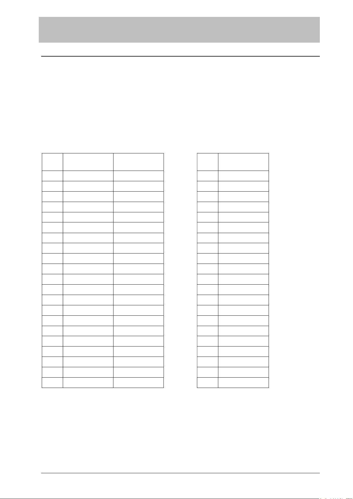
8 Appendix
Table: Relations between dB values, gain and level in dBu
dB Voltage and
Current Gain Power Gain dBu Voltage (RMS)
0 1 1 0 0.77459667
1 1.12201846 1.25892542 1 0.86911176
2 1.25892542 1.5848932 2 0.97515943
3 1.41253756 1.99526237 3 1.09414689
4 1.5848932 2.51188647 4 1.227653
5 1.77827941 3.16227766 5 1.37744931
6 1.99526237 3.98107192 6 1.54552359
7 2.23872111 5.0118722 7 1.73410591
8 2.51188647 6.30957362 8 1.94569889
9 2.81838285 7.94328191 9 2.18310997
10 3.16227766 10 10 2.44948974
11 3.54813399 12.5892548 11 2.74837277
12 3.98107192 15.8489337 12 3.08372505
13 4.46683568 19.952621 13 3.45999604
14 5.0118722 25.1188629 14 3.88217951
15 5.62341325 31.6227766 15 4.35587717
16 6.30957362 39.8107192 16 4.88737471
17 7.07945823 50.1187289 17 5.48372477
18 7.94328191 63.0957275 18 6.15283971
19 8.91250914 79.4328191 19 6.90359989
20 10 100 20 7.74596669
Table of contents
Popular Media Converter manuals by other brands


Hall Research Technologies
Hall Research Technologies SP-HD-4C user manual

WFCO
WFCO WF-7910 Series Operator's manual

Syscom Video
Syscom Video 8CH FX-TRON instruction manual

AEG
AEG ST 800 Operation and safety notes

Universal Tool
Universal Tool UT9912 operating instructions

NETGEAR
NETGEAR AGM733 installation guide