Estelon Extreme User manual

EXTREME USER MANUAL 1
EXTREME
USER MANUAL

2 EXTREME USER MANUAL
TECHNICAL SPECIFICATIONS
Woofer: 2x10” Aluminium dome (equal to surface of 2x11”)
custom design, Accuton
Mid Woofer: 10” Aluminium dome (equal to surface of 11”)
custom design, Accuton
Midrange: 7” Ceramic inverted dome
custom design, Accuton
Tweeter: 1,5” Diamond inverted dome
custom design, Accuton
Internal Wiring: Kubala-Sosna
Capacitors: Teflon-Hybrid
Inductors: Goertz copper foil, Mundorf transformer
Frequency Response: 20 - 45 000 Hz
Power Rating: 500 W
Amplifier Power: Minimum 20 W
Nominal Impedance: 4 Ohms
Sensitivity: 91 dB/2.83 V
Height: 5 adjustable heights 1770 - 2070 mm (69,7’’-81,5’’)
Width: 670 mm (26,4”)
Depth: 800 mm (31,5”)
Weight (Upper Module): 75 kg (165 lbs)
Weight (Lower Module): 175 kg (386 lbs)
Net Weight Total: 250 kg per loudspeaker (551 lbs)
Suggested room size 50-150 m2.
EXTREME USER MANUAL 3
UNPACKING INSTRUCTIONS
Your Estelon Extreme loudspeakers come packaged with each module in 4 separate flight
cases – we strongly recommend keeping these cases for possible future use / transport.
Bring the four flight cases for unpacking as close as possible to the speakers positioning
point*. Due to the substantial weight and slippery surface of the loudspeakers we suggest
that three (3) persons assist in the unpacking and positioning of them for listening.
Contents of the four (4) flight cases:
- Pair of loudspeakers:
• 2 Lower Modules
• 2 Upper Modules
- 4 Cloth bags to protect the speaker finish
- Belts for upper module positioning (#11 and #12)
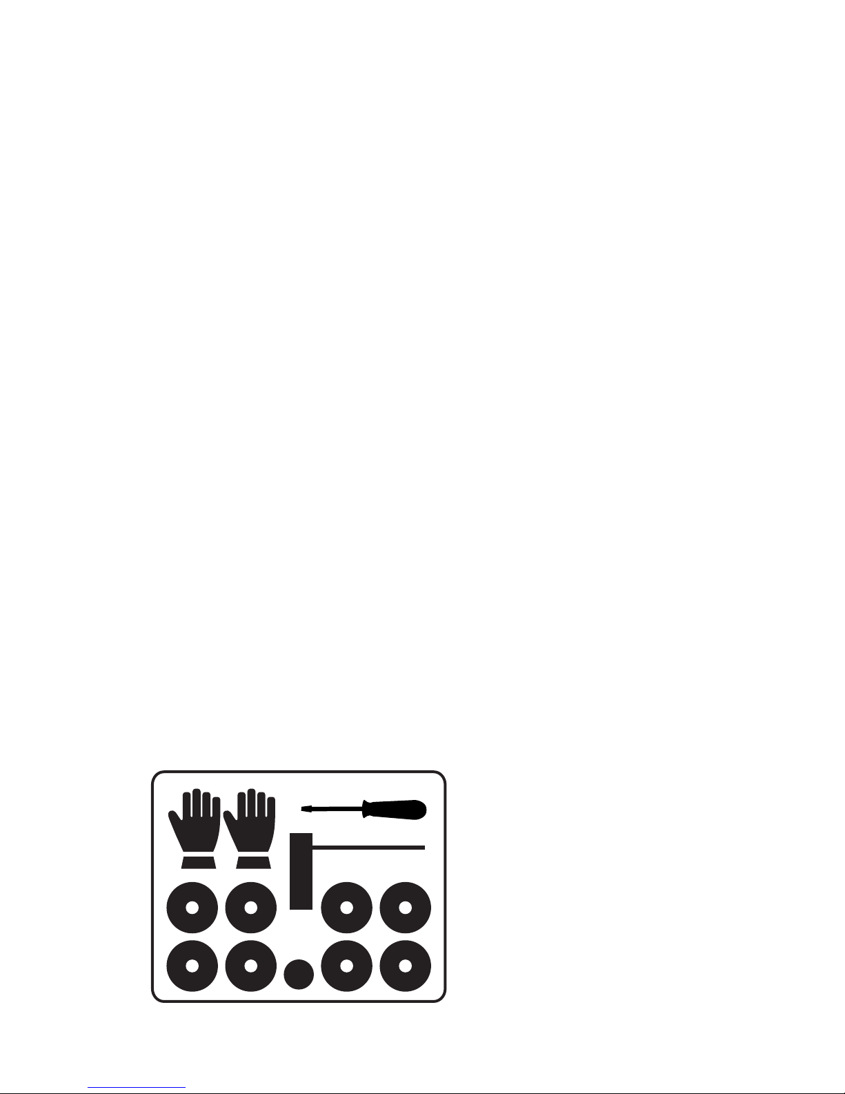
- 1 Accessories box (#1):
• 8 Loudspeaker feet with 8 adapters (#8)
• 1 Key for tweeter adjustment (#7)
• 1 Screw driver
• 1 User’s manual
• 3 Pairs of gloves and 1 Polishing cloth
- 1 Toolbox for speakers’ positioning (#2):
• 3 Lifting tools
• 1 Key for lifting tools
- 1 Controller box with connecting cable and power cord; remote control (#3)
- 1 package with softening mats (2 pcs) and two sided tape (#4)
- 6 wheels under each speaker (12 in total)
7
Accessories box
8

4 EXTREME USER MANUAL
Recommended positioning point:
The positioning of the speakers in the room must be symmetrical in order to achieve a bal-
anced sound stage – this is very important in a narrow room. Expect the distance between
the speakers to be approximately 3 - 6 m (10 - 20 ft), depending on the size of the room
and its reverberation characteristics.
When positioning the speakers in your room, if possible, it is desirable to allow for “free”
space around the speakers so as to assist in minimizing sound reflections from walls,
furniture etc. This will help in achieving correct tonality, realistic imaging, focus and
dynamics. The recommended minimum distance between the speaker and the nearest
reflection point is 1.2 m (4 ft).
The distance between the back wall and the speaker should not be less than 1 m (3,2 ft) and
the distance from the speakers’ front to the back and side walls must not be too similar.
The best listening point: the distance between your ears and the floor should be approx. 1 m
(4,2 ft), the distance between the listener and the speakers should be similar to the distance
between the two speakers.
The recommended speaker’s direction is approximately 5°-7°, off axis, towards the listening
position.

EXTREME USER MANUAL 5
Start with unpacking the Lower Module:
For unpacking, please follow the instructions described below and as shown in the
drawings.
NB! Please wear gloves supplied in the Accessories box when the cloth bags are removed
from the speakers.
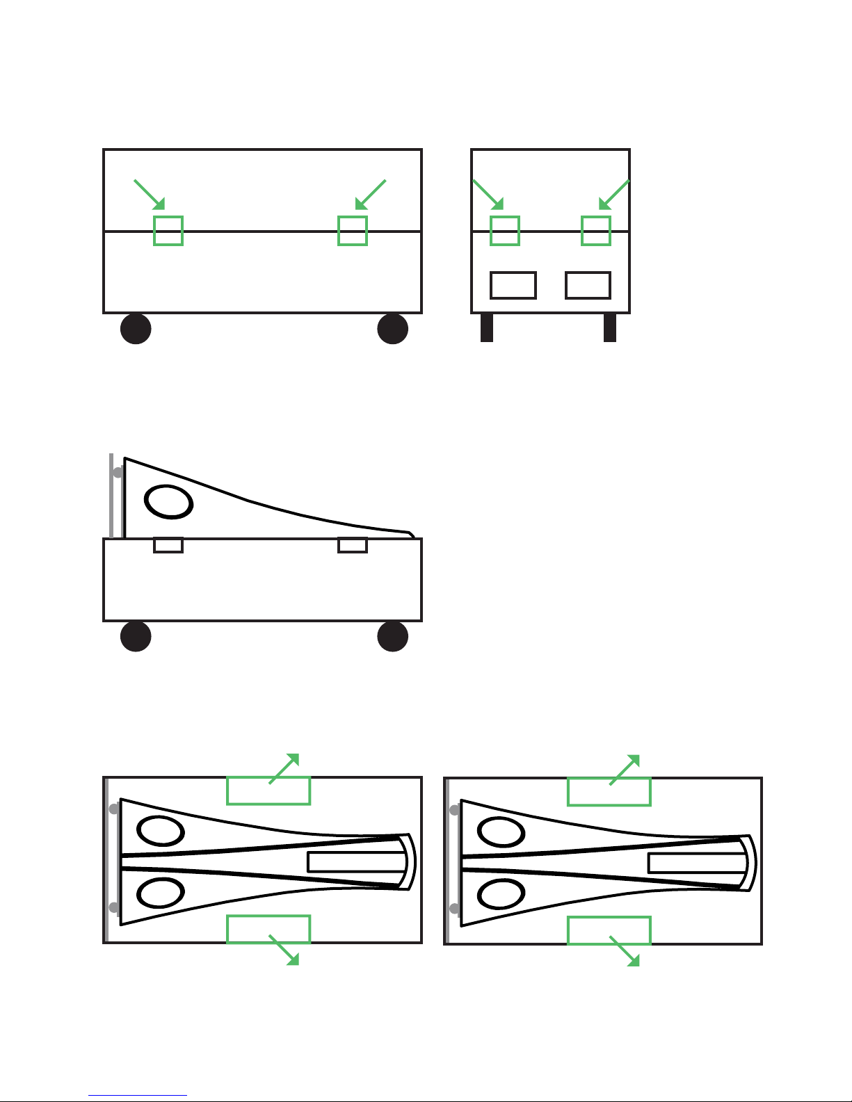
1. Unlock / Open all eight locks on the flight case cover. This should only be done with
the speaker / flight case in a horizontal position.
2. Carefully lift the cover off the flight case and put it aside.
3. Remove Accessories Box (#1), Toolbox (#2), Controller (#3) and a package with
softening mats (#4) from the flight case.
4. Do not touch drivers – note the warning stickers.
5. Gently, with one person lifting the flight case, and another person supporting the
speaker, elevate the flight case with the speaker to a vertical position. Please mind
the plywood platform (#6) - protect your feet.
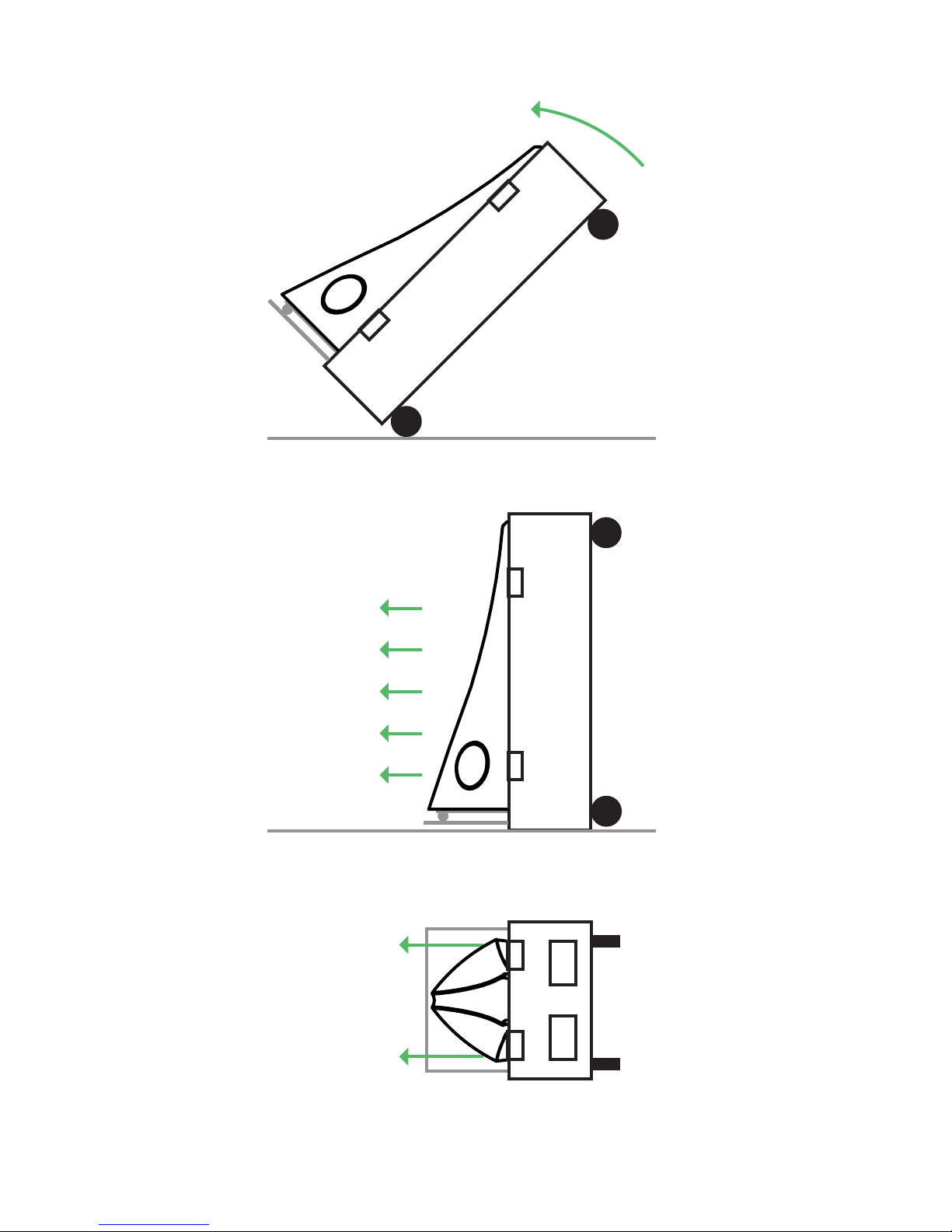
6. Now in an upright position, one person supporting the speaker, and two other
persons on each side of the speaker pulling the speaker from bottom edges, slowly
roll the speaker out of the flight case. Roll the speaker as close as possible to
the right position.
7. Remove the cloth bag.
8. Remove the top plate (#9).
9. Place the mat (#4) to the cabinet’s top as shown in the drawing using the
tape supplied.
10. Please repeat the procedures 1-9 with the second Lower Module.
6 EXTREME USER MANUAL
fig. 1
fig. 2
fig. 3
#5
#1 #3
#2 #4
EXTREME USER MANUAL 7
fig. 5
fig. 6
top view
#6

8 EXTREME USER MANUAL
fig. 7 fig. 8 fig. 9
#9

EXTREME USER MANUAL 9
Continue with unpacking and assembling the Upper Module:
Upper Module A must be assembled with Lower Module A, and Upper Module B must be
assembled with Lower Module B (please see serial number/product code).
11. Unlock / Open all four locks on the flight case cover. This should only be done with
the speaker / flight case in a horizontal position.
12. Carefully lift the cover off the flight case and put it aside.
13. Do not touch drivers – note the warning stickers.
14. Remove the softening pillow (#10) from the flight case and put it on the floor
(approx. 1 meter from the Lower Module).
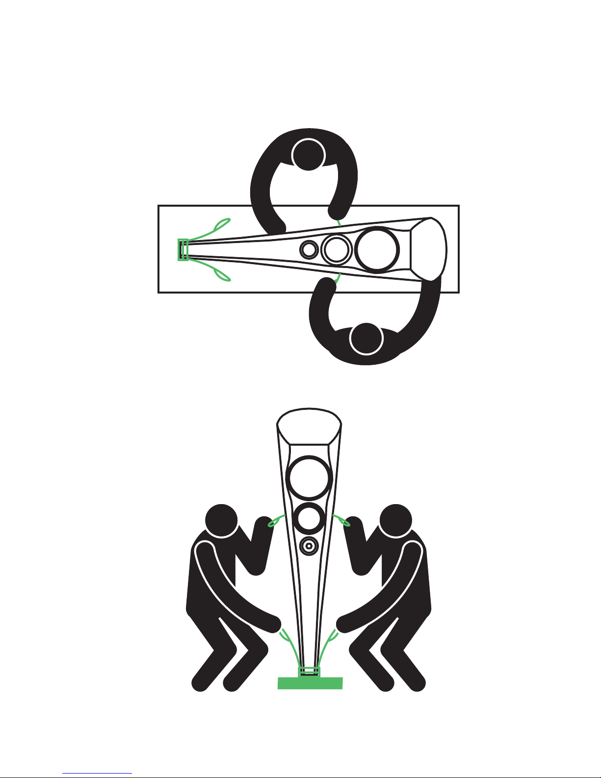
15. Now, supporting the speaker with one hand and holding the belt # 11 with the
second hand, take the speaker out of the flight case and place the lower part on the
softening pillow as shown in the drawing. This procedure must be carried out by two
strong persons – one on each side of the speaker.
16. Find the balance so it is easier to hold the speaker in a vertical position. The third
person should open the velcro on the back of the cloth bag. Now, while third person
supports the speaker, and the other two people take the belt #12 (still holding the
belt #11).
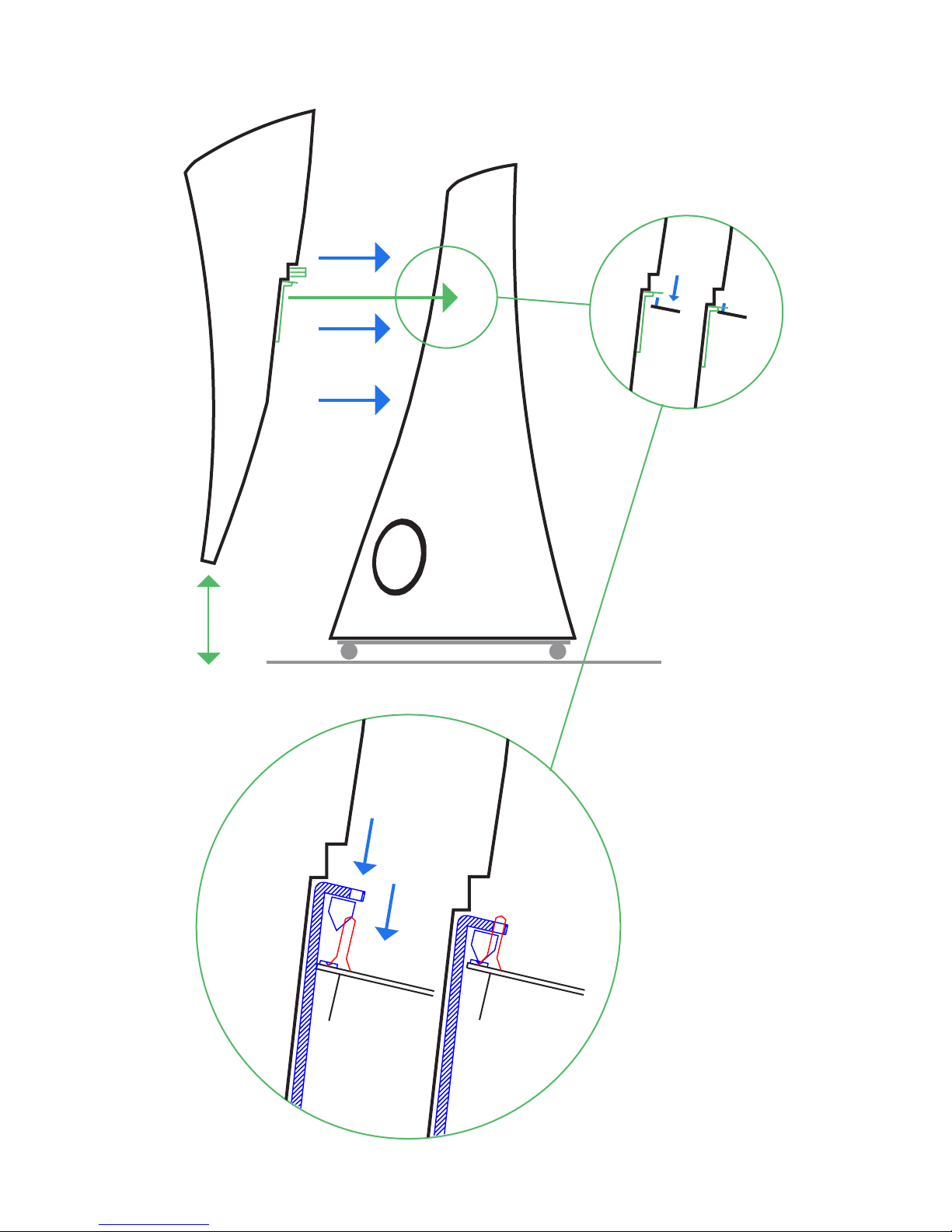
17. Please position the rear part of the Upper Module facing the front part of the Lower
Module (you may need to lift the speaker for turning it). Raise the speaker for approx.
30 cm from the pillow and adjoin with the Lower Module as shown in the drawing;
third person must support the Lower Module and protect it from moving (remember,
it is on cart).
18. Slowly, lower the Upper Module until the two cones are (#13) strongly fixed in
the grooves (#14).
19. Remove belt # 12.
20. Remove protective matte from the top of the Lower Module.
21. Remove cloth bag from Upper Module.
22. Please repeat procedure 11-21 with the second Upper Module.

10 EXTREME USER MANUAL
fig. 11
fig. 12
fig. 14
#10
#12 #11
#12 #11
EXTREME USER MANUAL 11
fig. 15
fig. 16
12 EXTREME USER MANUAL
fig. 17
fig. 18
30 cm

EXTREME USER MANUAL 13
Prepare the Controller and continue with assembling:
23. Take the Controller box from the suitcase #3.
24. Connect the Controller with both speakers via cable supplied.
25. Plug in power cord.
26. Switch on the controller.
27. Take the remote control and press arrow „up“ and move the Upper Module 4
positions upwards. After pressing the arrow speaker will stop in each position. Please
press an arrow again until it has reached the highest position (the Upper Module
stops raising when it has reached the highest position). Do not put fingers (or any
objects) between two modules.
28. Now take the screw driver from the Accessories Box (#1), stand on the chair/platform
and remove two screws (#15) from Lower Module’s top.
29. By pulling the red pipe (#18), remove the protection plate (#19). Now take out
the belt #11.
30. Connect cables (#16) with binding posts (#17).
31. Place the top plate (#9) back on the Lower Module. If necessary you can use the two
sided tape supplied in the Accessories box (#1).
32. Repeat procedures 28-31 with the second speaker.
33. Now press arrow „down“ on the remote control to move the Upper Module two po
sitions downward so the Upper Module moves to the middle position.
Keep the remote control out of reach of children!
Please keep all the removed parts for future re-assembling and/or transportation.
Now continue with the wiring:
When connecting the speaker to the amplifier please make sure that the amplifier is in an
off position.
Connect the speaker cable to the pole terminal on the back of the speaker: speaker terminal
„+“with the amplifier terminal „+“and „-“with „-“. For single wiring we recommend connect-
ing cables to upper binding posts (please keep the wire jumpers connected between upper
and lower binding posts).
For signal flow, please follow the direction marked on the cable or in the cable
manufacturer’s instruction. Typically, the signal flow will be in the same direction as
the labelling / writing on the cable.
Estelon Extreme can be also bi-amped or bi-wired at your choice. In this case remove wire
jumpers to be able to use all connectors. Connect one cable to upper binding posts and
another cable to lower binding posts: speaker terminal „+“with the amplifier terminal „+“
and „-“with „-“.

14 EXTREME USER MANUAL
fig. 27 fig. 28
#17
#16
#16
#15
#15
#18
#19
EXTREME USER MANUAL 15
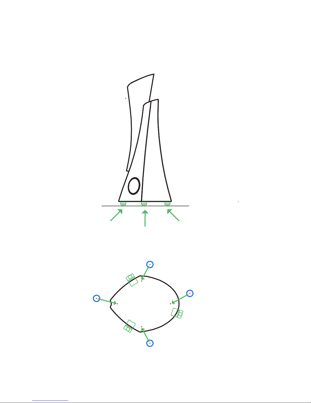
fig. 35
Bottom view, where to
connect the feet.

16 EXTREME USER MANUAL
Break-in period:
Although your Estelon speakers had an initial break-in at the factory, due to shipping
conditions - pressure/temperature changes that they may have incurred, the speakers will
need to go through an additional break-in process before their final set-up and tuning.
All the mechanical and electrical connections will stabilise naturally after playing a
continuous music signal for approx. 24 hrs – e.g. use a digital source in the repeat mode.
After the initial break-in period you can start final tuning.
Please note that the speakers will have reached their optimum level of performance after
playing in your system for 300-400 hrs.
Now continue with final tuning:
Find the best possible position for the speakers in the room. You can move the speaker by
pulling it from the bottom edges (it will slide on cart).
Estelon Extreme allows you to adjust the speaker height for optimising the sound in regard
of audience’s position and room specifics. It has 5 different heights (each step 300 mm).
By changing the height:
- you change the combinations of sound reflections in the room. This way you can find
the best position in Your room for achieving the best sound.
- you also change the vertical position of the stereo picture.
To understand which position is best in Your room, please listen to the speakers in all 5
different positions/heights. Choose the best position.
Depending on the chosen height, height of and the distance from the listening point, and
room acoustics, you may need to adjust the tweeter to achieve the right timing of the
drivers. Choose the position where the sound is most coherent.

EXTREME USER MANUAL 17
Tweeter has three positions. Take the Key for tweeter adjustment (#7) from Accessories
Box. Find the key hole on the right of the Upper Module at tweeter level. Insert and turn the
key 90 degrees clock-wise to change the tweeter position (please do not turn the key
anticlockwise). Continue turning it clockwise – positions will change along the circle.
Choose
When speakers positioned and tuned, it is time to insert feet and remove cart:
1. Open the Toolbox (#2) with lifting tools. Place them (3 pieces) under the speaker as
shown in the drawing.
2. Use the Key supplied in the Toolbox to raise the lifts (move the key back and forth
several times). We recommend that one person supports the speaker while second
person raises lifts. Please raise lifts gradually to avoid tilting the speaker too much.
Raise all lifts alternately until the height is sufficient for rolling the cart out from the
bottom of the speaker.
3. Now take the feet (#8) (4 pcs for each loudspeaker) supplied in Accessories box and
screw them in the holes on the bottom of the loudspeaker as shown in drawing.
4. Now switch the Key to loosening position and descend the lifts one by one, gradually,
xuntil the speaker stands on feet. Remove the lifts.
In case of the need to move the speakers in the room please use lifts to raise the speaker,
then slide the cart under the speaker. You can move the speaker by pulling it from the
bottom edges (it will slide on cart).
w
To avoid any possible influence on the sound we recommend to remove the Controller while
using the speakers.
For packing follow the same procedures in the opposite direction.
If you have any questions, please contact authorised Estelon dealer for assistance.

18 EXTREME USER MANUAL
ESTELON / ALFRED & PARTNERS - TECHNICAL SERVICES
Alfred & Partners OÜ Five Year Limited Warranty
Terms and Conditions
1. Limited Warranty - All ESTELON products purchased from authorised ESTELON
dealers are covered by a limited 5-year non-transferrable warranty granted by Alfred
& Partners OÜ. This warranty includes all parts and labour charges as well as
return-shipping charges (product owner is responsible for all shipping and insurance
charges one-way to the ESTELON repair facility).
Upon receipt of an online registration form, Alfred & Partners OÜ warrants the
purchased product to be free from manufacturing, materials, and workmanship
defects for five years from the date of original purchase, subject to the following
conditions. Failure to register the ESTELON product within 30 days from original
purchase will result in a warranty period of 90 days from the date of purchase.
Customers should consult with their original ESTELON dealer or distributor for
possible alternate repair instructions prior to contacting the ESTELON factory. Other
ESTELON dealers or distributors may refuse from assisting the Customer under the
limited warranty BUT under any and all circumstances customers are welcome to
contact our sales department, listed on our web site www.estelon.com, for service
assistance.
This limited warranty is valid only in the country where the product was originally
purchased. If the repair request that is covered under this warranty comes from
another country then the Manufacturer may request the Customer to compensate
to the Manufacturer additional costs arising from providing this limited warranty in
another country than the country of original purchase.
This limited warranty shall not affect the statutory rights of the Customer.
2. Limited to Original Purchaser - This warranty is for the sole benefit of the original
purchaser of the covered product, and may not be transferred to a subsequent
purchaser of the product.

EXTREME USER MANUAL 19
3. Conditions and Limitations - This warranty is subject to certain conditions and
limitations, as follows. This warranty is void and inapplicable if the product has not
been used in accordance with the instructions found elsewhere in the owner’s
manual, or if it has been misused or abused, damaged by accident or neglect, or in
transport once in possession of the purchaser. The warranty is also deemed void if
the product has been repaired, modified, or tampered with by anyone other than
Alfred & Partners OÜ or its specifically authorized agents. Please Note – if the
fasteners to the cover of the crossover area, those covered with multi coloured
specialty epoxy seal, have been tampered with / the epoxy removed – the warranty
will considered to be void.
This warranty does not cover defects due to accidents or similar causes arising after
the risk for the product has passed to Customer, or normal deterioration, wear and
tear.
4. Remedy - If this product contains a material, manufacturing, or workmanship
defect that cannot be repaired at the dealership where the product was purchased,
it must be packed in original packaging and returned to Alfred & Partners OÜ via
insured freight, at the owner’s expense. If replacement packaging materials are
required, they may be purchased from the factory at a charge. Returned products
must be accompanied by a written description of the defect, and a return
authorisation number (available from the factory via phone or email).
Upon receipt of defective product, ESTELON agrees to repair the product without
charge for parts or labour. The product will then be returned via prepaid, insured
freight, with carrier at the sole determination of ESTELON. This constitutes the pur
chasers sole remedy.
5. Design Changes - ESTELON reserves the right to modify its products or change
specifications at any time without obligation or liability to previous purchasers.
6. Miscellaneous - Any implied warranties relating to the above product shall be limited
to the duration of this warranty. This warranty does not extend to any incidental or
consequential costs or damages to the purchaser. This warranty gives you specific
legal rights. You may also have other rights which vary from country to country.

20 EXTREME USER MANUAL
INSTRUCTIONS FOR OBTAINING REPAIR SERVICE
1. Complete the Return Authorization Request Form – available online at
estelon.com/support.
2. Upon clicking the ‘Submit’ button on the Return Authorization Form, the ESTELON
factory will review it for completeness and return an e-mail to you with an RA
number when required (please allow 2-5 days for a return e-mail).
3. Crate and / or package the product in its ORIGINAL FLIGHT CASE CONTAINERS
ONLY, according to the instructions included in the return e-mail, and ship the
product to the shipping address included in the e-mail. The owner is responsible for
paying the shipping and insurance charges (Alfred & Partners OÜ will cover return
shipping and insurance charges on warranty repairs).
4. In the case of non-warranty repairs, Alfred & Partners OÜ will physically inspect the
product and contact the customer for repair approval. Upon approval and completion
of repair, the product owner will be informed of the final charges (including return
shipping). Payment may be made by bank / wire transfer prior to final shipment).
Payments not received within 30 days of initial contact may incur storage fees.
We strongly recommend that all product repairs should be conducted through the
ESTELON factory or an authorized ESTELON repair facility. ESTELON products are
designed and manufactured to the highest tolerances with numerous hand-picked
components; for this reason, we HIGHLY RECOMMEND that components not be serviced
by non-authorized repair facilities. Alfred & Partners OÜ values its loyal customers and will
make every attempt to return repaired products to their original factory specifications.
Customers should consult with their original ESTELON dealer or distributor for possible
alternate repair instructions prior to contacting the ESTELON factory. BUT under any and
all circumstances customers are welcome to contact our sales department, as listed on our
web site www.estelon.com, for service assistance. All non warranty repairs are warranted for
one year from the date of return shipment.
Have we answered all your questions?
If not, please send us an email with your questions to sales@estelon.com
www.estelon.com
Other manuals for Extreme
1
Table of contents
Other Estelon Speakers manuals

Estelon
Estelon Forza User manual

Estelon
Estelon Alfred Vassilkov Limited YB Mk II User manual

Estelon
Estelon Forza User manual

Estelon
Estelon Extreme Mk II User manual

Estelon
Estelon XA User manual

Estelon
Estelon Extreme User manual

Estelon
Estelon YB User manual

Estelon
Estelon X Diamond Mk 2 User manual

Estelon
Estelon X Diamond User manual

Estelon
Estelon XB Mk II User manual


