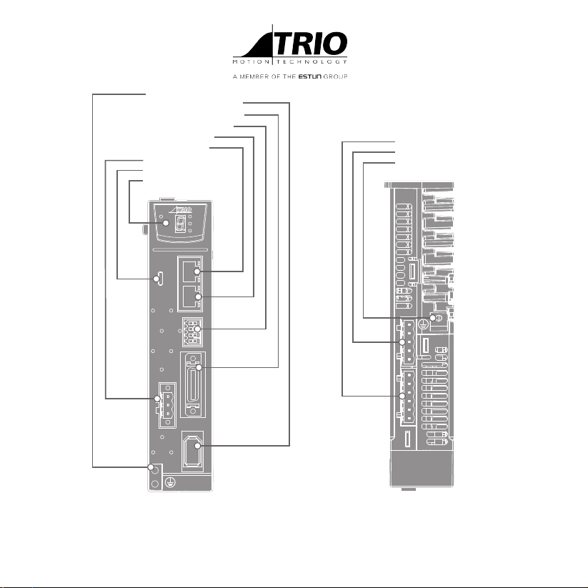
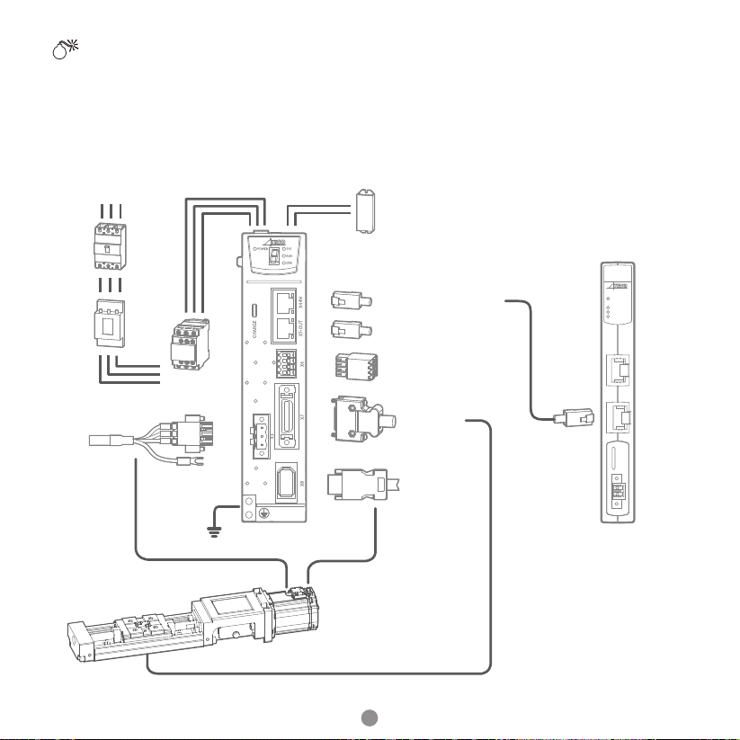
4
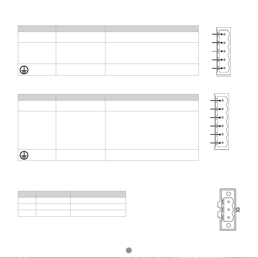
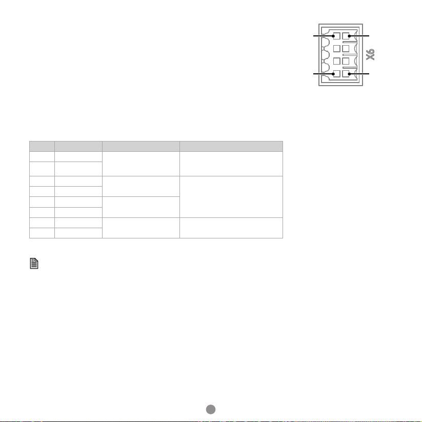
POWER SUPPLY CONNECTORS (X1, X2)
Symbols Name Specications and Reference
L1C, L 2C Control power supply
terminals
Single-phase, 200V ac to 240V ac, -15% to +10%,
50Hz or 60Hz
B1, B2, B3 Regenerative Resistor
terminal
There is a factory t short between B2 and B3.
When the busbar capacitance is insucient,
remove the short wiring, and connect an external
regenerative resistor between B1 and B2.
Ground terminal Always connect this terminal to prevent electric
shock.
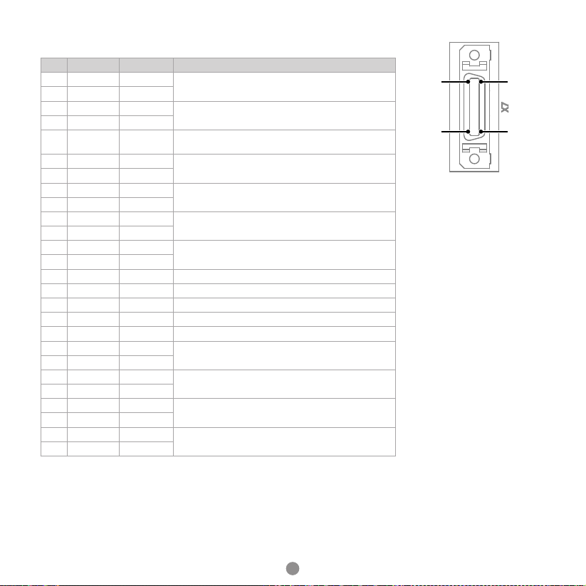
POWER SUPPLY CONNECTORS (X2)
Symbols Name Specications and Reference
L1, L2, L3 Main circuit power supply
input terminals
Three-phase, 200V ac to 240 V ac, -15% to +10%,
50Hz or 60Hz
P1, P2, N DC terminals
There is a factory t short between P1 and P2.
For using a DC reactor, remove the short wiring,
and connect a DC reactor between P1 and P2.
For using a DC power supply, connects P2 to the
positive pole, and connects N to negative pole.
For the common DC bus, connect all P2 of Drive to
the positive pole, and N to the negative pole.
Ground terminal Always connect this terminal to prevent electric
shock.
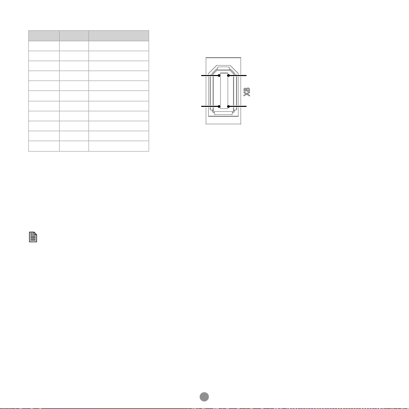
MOTOR POWER CONNECTOR (X3)
Pin Symbol Colour
1 U Brown
2 V Gray
3 W Black
X1
X2
L1C
L2C
B1
B2
B3
L1
L2
L3
P1
P2
N
X1
X2
L1C
L2C
B1
B2
B3
L1
L2
L3
P1
P2
N