Friendess FSCUT4000E User manual

Installation
FSCUT4000E User Manual

FSCUT4000E User Manual
2
Table of Contents
Table of Contents ................................................................................................................................ 2
Chapter 1 Overview ............................................................................................................................ 4
1.1 Introduction .......................................................................................................................... 4
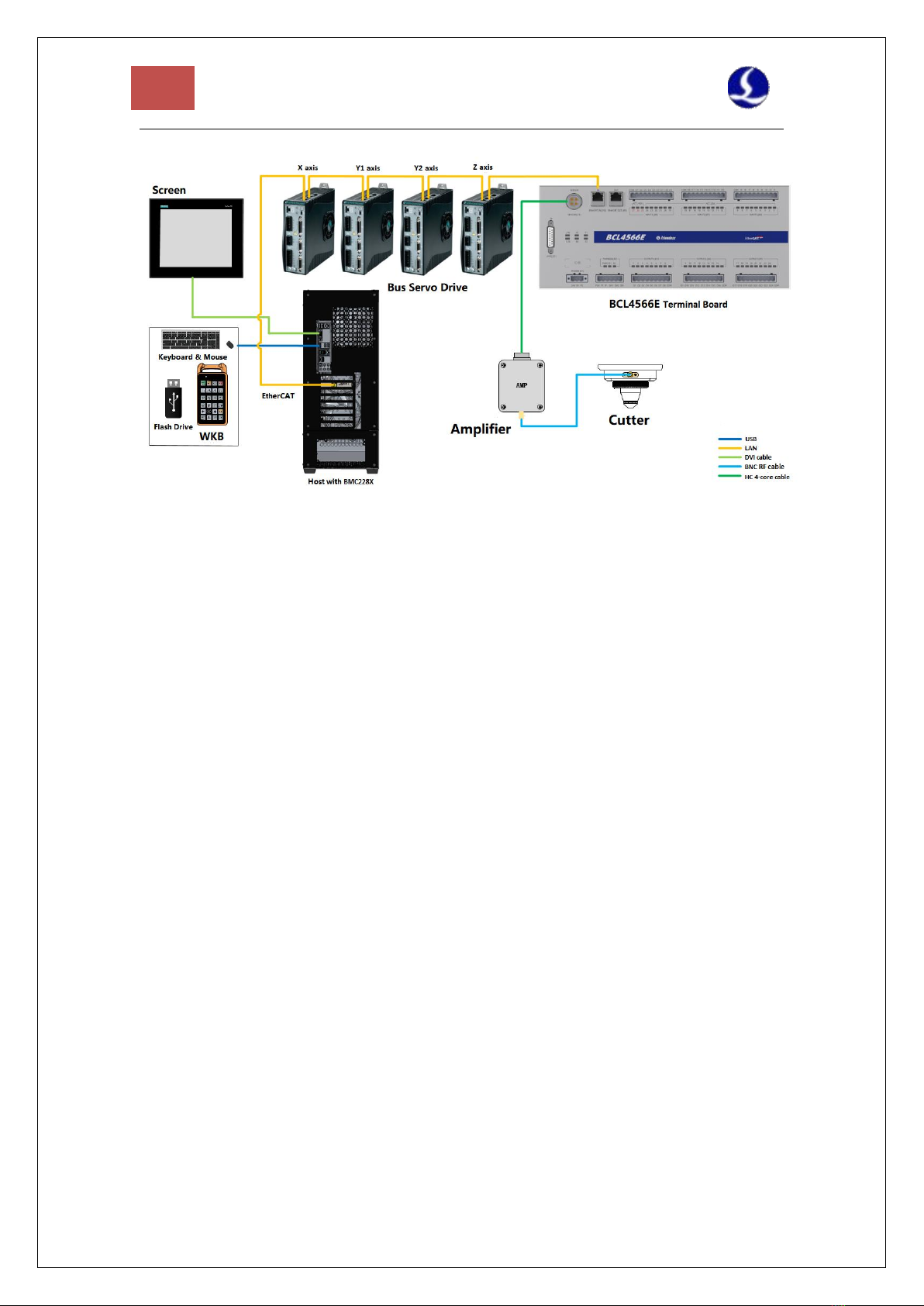
1.2 System Diagram .................................................................................................................... 4
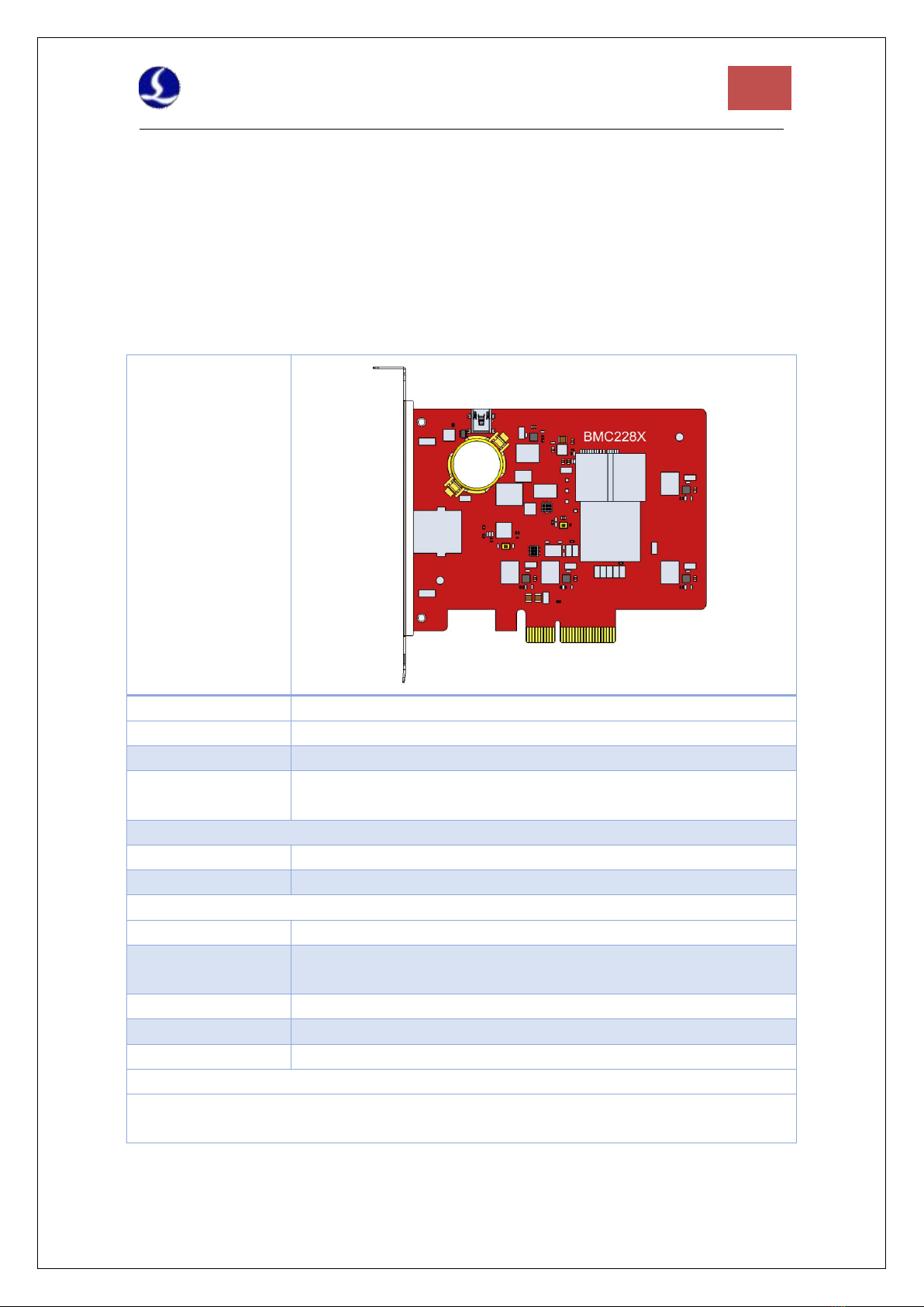
1.3 Product Details ......................................................................................................................6
Chapter 2 Wiring Instruction .............................................................................................................. 8
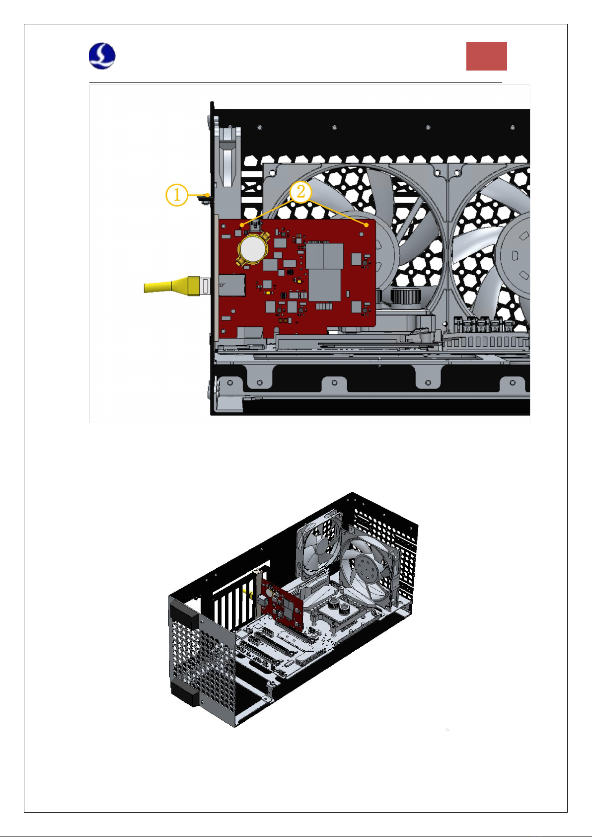
2.1 BMC228X Installation ............................................................................................................8
2.1.1 Dimension Diagram ................................................................................................... 9
2.1.2 Installation Diagram ...................................................................................................9
2.1.3 Ethernet Terminal .................................................................................................... 11
2.1.4 PCIE Socket ...............................................................................................................12
2.2 HPL2720E Wiring ................................................................................................................ 13
2.2.1 Interface Layout ....................................................................................................... 14
2.2.2 J01 EtherCAT Input Terminal ....................................................................................14
2.2.3 J02 EtherCAT Output Terminal .................................................................................14
2.2.4 J03 Power Input Terminal ........................................................................................ 14
2.2.5 J04 PWM Output Terminal ...................................................................................... 15
2.2.6 J05 DAOutput Terminal ............................................................................................16
2.2.7 J06 Common Output Interface ................................................................................ 16
2.2.8 J07 Common Input Interface ................................................................................... 17
2.3 BCL4566E Wiring .................................................................................................................19
2.3.1 Interface Layout ....................................................................................................... 20
2.3.2 J01 Power Supply ..................................................................................................20
2.3.3 J02PWM/DA Terminals .........................................................................................21
2.3.4 J03/J04/J05 Output Terminal ................................................................................22
2.3.5 J06/J07/J08 Input Terminal ...................................................................................22
2.3.6 J09/J10 Network ................................................................................................... 24
2.3.7 J11 Sensor ............................................................................................................. 25
2.3.8 J12DB15 Servo Axis Interface ............................................................................... 25
2.4 Cutter Wiring .......................................................................................................................29
2.4.1 ProCutter Wiring ......................................................................................................29
2.5 Laser Wiring ........................................................................................................................ 30
2.5.1 IPG_ YLS Germany ....................................................................................................30
2.5.2 IPG_ YLS American ...................................................................................................31
2.5.3 Raycus ...................................................................................................................... 32
2.5.4 Trumpf ......................................................................................................................33
Chapter 3 Installation ........................................................................................................................34
3.1 Installation Steps .................................................................................................................34
3.1.1 Step 1. Install BMC228X Control Card ..................................................................... 34
3.1.2 Step 2. Install MC228X Driver ..................................................................................34

3
FSCUT4000E User Manual
3.1.3 Step 3. Connect slave ...............................................................................................35
3.1.4 Step 4. Scan in Cypfig ...............................................................................................35
1.3.1 Step 5. Use CypCutE .................................................................................................35
Chapter 4 Precautions .......................................................................................................................36
4.1 Wiring Precautions ..............................................................................................................36
4.1.1 Drag Chain Wiring ....................................................................................................36
4.1.2 Machine Tool Wiring ................................................................................................38
4.1.3 Assembly Requirements .......................................................................................... 40
4.2 Troubleshooting .................................................................................................................. 40
4.2.1 Device Manager cannot find PCIe devices .............................................................. 40
4.2.2 Device Manager cannot install driver ......................................................................41
4.2.3 Bus Scan failed ......................................................................................................... 41
4.2.4 Bus network alarm ...................................................................................................42

FSCUT4000E User Manual
4
Chapter 1 Overview
1.1 Introduction
FSCUT4000E is a cost-effective CNC system dedicated to laser cutting. It is based on EtherCAT
bus technology and capable of motion control, laser control, and cutting gas control. It is common
used in sheet metal, kitchen ware, lamps and such industries. This user manual is only for
installation guidance.
1.2 System Diagram
FSCUT4000E includes the bus BMC228X Control Card, the bus IO board, and the bus height
controller, among which the BMC228X control card integrates the EtherCAT master protocol
stack.
The network cable is led out from the network port of BMC228X and connected to the BLT
cutting head. The wiring diagram is shown in Figure 1.
Figure 1 Wiring diagram of FSCUT4000E - BLT cutter
The wiring diagram of other cutting head is shown in Figure 2.

5
FSCUT4000E User Manual
Figure 1 Wiring diagram of FSCUT4000E - other cutter

FSCUT4000E User Manual
6
1.3 Product Details
FSCUT4000E bus CNC system includes BMC228X Control Card, BCL4566E terminal board or
BCS210E height controller, HPL2720E, WKB V6 and related cables, etc.
BMC228X Control Card
(1)
BCS210E Motion Control
(1)
HPL2720E EtherCAT Terminal Board
(1)
WKB V6
(1)
LAN-20X-PWE Wire
(1)
LAN Cables
LAN-0.5X (4)
LAN-1X (2)
LAN-3X (1)
Table 1-1 FSCUT4000E - BLT cutter details

7
FSCUT4000E User Manual
BMC228X Control Card
(1)
WKB V6
(1)
BCL4566E Terminal Board
(1)
BNC RF cables
(2)
Amplifier
(1)
HC 4-core cable
(1)
LAN Cables
LAN-0.5X (4)
LAN-1X (1)
LAN-3X (1)
Table 1-2 FSCUT4000E - other cutter details

FSCUT4000E User Manual
8
Chapter 2 Wiring Instruction
2.1 BMC228X Installation
BMC228X Control Card is a motion control card based on the EtherCAT bus. Its 1.0Ghz
main chip provides excellent overall performance and has passed Friendess stringent testing
standards.
BMC228X
EtherCAT Control
Card
Bus Protocol
EtherCAT Master Protocol
PCI Express
PCI Express2.0 (Gen2)
Power Supply
Powered by PCIe motherboard, max 12V/1A, no hot plug
Anti-interference
Level
ESD 3 (6kV contact, 8kV air), EFT 4 (4kV power supply, 2kV signal), Surge
international 2 (2kV AC line, 1kV DC line)
Dimension and Weight
Dimension
(L x W x H) 127.6mm x121.0mm x21.45mm
Weight
80g
Features
Cooling
Nature Cooling
Operating
temperature
0~+60℃
Storage temperature
-20~+70℃
Humidity
0% to 90% (non-condensation
Certification
CE
Environment Requirements
The waterproof and dustproof grade of the Control Card is IP00, unprotected. Please place
the computer in a clean, dust-free environment.
Table 2-1 BMX228X Technical Data

9
FSCUT4000E User Manual
2.1.1 Dimension Diagram
BMC228X Control Card dimension ( mm) is shown in Figure 3.
Figure 3 BMC228X Dimension
2.1.2 Installation Diagram
Install BMC228X in the socket of PCIE X4 and up with even force (refer to ②), and
secure its blank screw (refer to ①). Be aware of the heat dissipation for BMC228X and keep it
away from other cards as far away as possible. Refer to the diagram below.

FSCUT4000E User Manual
10
Figure 4 BMC228X Control Card Installation
BMC228X installed is shown below.
Figure 5 BMC228X Control Card After Installation

11
FSCUT4000E User Manual
2.1.3 Ethernet Terminal
The standard socket of BMC228X is RJ45 that can be used to connect EtherCAT slave
devices(servo drives, BCS100E, HPL2720E, etc.)
Label
Description
LED color
Status
Description
1: Speed
Ethernet
communication
connection
speed
Green
Off
10 Mbps connection
Solid
100 Mbps connection
2: Link
Ethernet
communication
link status
Yellow
Off
No connection
Flashes
Communicating
Solid
Connected
Table 2-2 Description of RJ45 connection status

FSCUT4000E User Manual
12
2.1.4 PCIE Socket
BMC228X PCIE socket is X4 (Figure 6①)and can be used for X4, X8, X16. Its PCI Express
Protocol standard is V2.0 (Gen2) and the motherboard requirements are as shown in Table 2-3.
Figure 6 Gold Fingers
System
64-Bit Win7/10
CPU
Intel i3 8100 and up
Memory
4GB and up
PCIE Socket
X4 and up
PCI Express
PCI Express2.0 (Gen2) and up
Motherboard PCIE power
supply
12V/1A and up
Table 2-3 Motherboard Requirements

13
FSCUT4000E User Manual
2.2 HPL2720E Wiring
HPL2720E is an IO extend board based on the EtherCAT bus, which supports the
peripheral resources required by the FSCUT6000 high-power cutting system, as shown in
Table 2-4.
HPL2720E
Module
Qty
Description
Note
Power
Supply
/
24V DC/5A
PWM
1
24V, ±50kHz 0.3%
Max 50kHz,3%
DA
4
0-10V, 12bit, ±20mV
Common
Output
20
High level 24V output, ≤ 0.7A per channel
The total current output ≤ 2.5A
External relay
recommended
Common
Input
27
24V level, active low (<15.6V); IN1~IN3 can be
switched to active high (>5.8V)
Working
Environment
Temperature: 0~60℃
Humidity: 10%~90% (no condensation)
Dimension
195×118×45.2mm
Weight
480g
Table 2-4 HPL2720E Hardware Resources

FSCUT4000E User Manual
14
2.2.1 Interface Layout
The interface layout of the HPL2720E terminals is shown in the figure below.
2.2.2 J01 EtherCAT Input Terminal
EtherCAT network cable input interface, standard RJ45 network cable;
2.2.3 J02 EtherCAT Output Terminal
EtherCAT network cable output interface, standard RJ45 network cable;
2.2.4 J03 Power Input Terminal
Notice
24V and 0V are respectively connected to the positive and negative poles of the DC
24V switching power supply; FG needs to be reliably connected to the ground, and
the ground wire should be as short and thick as possible.
All terminals are pluggable only, and disassembly is shown in the right figure above.
There is no need to unplug the terminals for wiring.

15
FSCUT4000E User Manual
2.2.5 J04 PWM Output Terminal
HPL2720E has a PWM pulse width modulation signal, which can be used to control the laser
power. The PWM signal level is 24V. The duty cycle is continuously adjustable from 0% to 100%,
and the max carrier frequency is 50KHz.
The signal output mode is shown in the figure below.
Note: The P+ and P- signals have enabled solid-state relays inside, and no external
relays are needed for isolation!

FSCUT4000E User Manual
16
2.2.6 J05 DA Output Terminal
HPL2720E has 4 analog outputs of 0~10V. The four-way DA can be configured as the
control signal of the laser peak power and the gas proportional valve through the "Cypfig"
that comes with the CypCutE software.
2.2.7 J06 Common Output Interface
OUT1~OUT20, total 20 high-level 24V outputs In the "Cypfig" that comes with
CypCutE, the output port can be configured as "height controller", "laser", "cutting head",
"auxiliary gas", "alarm", "pallet changer" and other related controls interface.
Note: Only DC loads can be connected, the output current of each channel must be ≤
0.7A, and the total current of the output port must be ≤ 2.5A, otherwise the short
circuit protection will be triggered.
If you need to connect to an AC load, please connect an external relay;
Output Signal
0~10V
Maximum Output
50mA
Maximum Error
+/-20mV
Resolution
2.7mV
Conversion
400us
Table 2-5 DA Output

17
FSCUT4000E User Manual
2.2.8 J07 Common Input Interface
HPL2720E does not set a dedicated input, and each input port can be set as limit/origin
signals
The Normally Open and Normally Closed modes of the limit and origin signals can be set in
the "Cypfig" that comes with CypCutE. When it is set to NO, the input is valid when the
input port is connected to 0V; when it is set to NC, the input is valid when it is disconnected
from 0V.
The typical connection of the photoelectric switch is shown in the figure below, and an NPN
type 24V photoelectric switch must be used;
The typical connection of mechanical contact switch is shown in the figure below;
The typical connection of the magnetic induction switch is shown in the figure below, and the
NPN type 24V magnetic induction switch must be used;
Among them, IN1~IN3 can adjust the polarity of the effective level through hardware
jumpers:

FSCUT4000E User Manual
18

19
FSCUT4000E User Manual
2.3 BCL4566E Wiring
The BCL4566E bus height controller uses the EtherCAT bus to control the laser cutting
capacitive follower. It is a high-performance capacitive height controller.
BCL4566E
Terminal Board
Module
Qty
Description
Power Supply
/
24V DC /3.5A
DA
2
0-10V, 12bit, ±50mV
PWM
2
5V and24V, ±50KHz 0.3%
Common
Output
24
24V active high
1) The current of single output ≤ 0.7A
2) The current of all outputs ≤ 2.5A
Axis
1
Pulse digital quantity, PUL±/DIR± output, up to 600KHz
Dedicated
Input
27
IN1-IN24, active low, 0~ 15V
IN25-IN27, active high, 24~ 8V
Capacitance
Sensor
1
Capacitance frequency 2Mhz~4Mhz
Working
Environm
ent
/
Temperature: 0℃~60℃
Humidity: 10%~90%Rh(no(no condensation)
Dimension
/
300mm×123×34mm
Weight
/
640g
Table 2-6 BCL4566E Technical Data

FSCUT4000E User Manual
20
2.3.1 Interface Layout
BCL4566E interface layout of terminals
Figure 2.3.1 BCL4566E interface terminals
2.3.2 J01 Power Supply
Figure 2.3.2 Power Supply Terminal
The machine case is the negative pole of the measured capacitance. In order to ensure the
stable operation of the measurement circuit, the "FG pin" of the power interface must be reliably
connected to the machine case (that is, it is in good conduction with the machine case). The case
of the preamplifier of BCL4566E must also be connected with the machine case well. The
specific index is that the DC impedance is always less than 10 ohms, otherwise the EMC effect
may not be good.
Table of contents
Other Friendess Control System manuals
Popular Control System manuals by other brands

Philips
Philips Lytemode 6-Button Remote Station user guide

Lutron Electronics
Lutron Electronics Stanza installation instructions

nvent
nvent RAYCHEM ACS-30 Programming guide

SMA
SMA SUNNY BOYSTORAGE Service manual

Keystone RV
Keystone RV SolarFlex 600i-L quick start guide

Mitsubishi Electric
Mitsubishi Electric MELDAS C6 Parameter manual