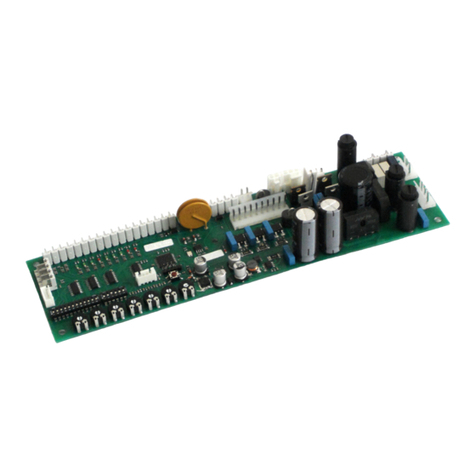
Estyma Vide User manual


page 2
PL20130524

Content
Index
1 General information 4
1.1 Introduction 4
1.2 Elements of the set 4
1.3 Precautions 5
1.4 Procedure with the used equipment
2 Connection
2.1 Electrical wiring
2.2 Location 7
condensation. 7
2.3 Installation 7
2.4 Description of connections 8
3 Review of functions 9
3.1 Control of binary output 9
3.2 Information about input condition 9
3.3 Information about the controller of boiler 10
3.3.1 Commands of queries about the parameters of boiler controller.............................10
4 Main display 12
5 Main menu 13
5.1 Sensors 13
5.2 Binary output 14
5.3 GSM settings 15
5.4 Settings 15
5.5 Notices 15
5. Language 1
5.7 Remote control panel 1
Specification 17
estyma electronics
.estyma.pl
page 3
PL20130524

1 General information
1 General information
Than you for choosing our product. We congratulate you on making a good decision. We
elcome any remarks on the operation of device.
Team
ESTYMA electronics
1.1 Introduction
VIDE GSM communication module is a multifunctional device designed for remote
access to the information of module sensors and controller of hot ater boiler by means of
GSM net ork.
The module is equipped ith t o slots of temperature sensors, t o slots for contact
input and output and CAN interface. Configuration, user-friendly panel makes it possible to set
SMS notices about important changes in the operation of sensors, such as:
•exceeding the range of room temperature allo ed
•alarm hen the input contact is closed or open, used for giving notice about the
opening/shutting of doors, gates, garages.
Contact output (binary), makes the remote activation/disconnection of any electrical
equipment possible. Using mobile, you can also read out current parameters of module as ell
as make chnages in settings.
By means of CAN interface, the Vide GSM module can remotely control the operation of
heating controller of IGNEO line, and make changes in the operation modes of boiler, burner
and 16 central heating circuits at most. The GSM communication system makes it possible to
make several changes in the controller operation and to read out current parameters displayed
on your mobile by sending SMS.
1.2 Elements of the set
1. Vide GSM module
2. 2x sensor of room temperature CT2a / 2.4
3. Po er unit
page 4
PL20130524

Content
1.3 Precautions
•Before y
ou start to operate the device, read the hole attached user`s guide carefully.
•Keep the user`s guide and refer to it in case you operate the device in future.
•Observe all the rules and arnings included in the user`s guide.
•Make sure the device is not damaged in any ay. In case of doubt, do not operate the device and
contact the suppier.
•In case of doubt concerning a safe operation of device, contact the suppier.
•Special attention should be paid to arning signs, housing or packaging of device.
•Operate the device according to its intended use.
•The device is not a toy, children should be prohibited from playing ith it.
•On no account can children play ith any part of the packaging of this device.
•
Children should be prevented from accessing small parts, for example, clamping scre s, pins.
These elements can be found on the equipment of device supplied and in
case of s allo ing they
can lead to the choking of child.
•No mechanical or electrical modifications can be made in the device. Such modifications can
cause the rong operation of device, incompatible ith standards or they can influence the
operation of device in a negative ay.
•No objects should be put into the device through gaps (for example ventialtion gaps). This can
cause short circuit, fire or damage to the device.
•Take care that no ater, moisture, dust and dirt gets into the device. This can cause short circuit,
electrical shock, fire or damage to the device.
•Make sure the device is ventilated properly, do not cover ventilation holes and provide a free flo
of air around it.
•The device should be installed inside the rooms.
•Make sure the device is not exposed to impacts and vibrations.
•Connecting the device, make sure that electric parameters of po er supply net ork are ithin
the operation range of device.
•Any connections must be compatible ith the installation electrical iring diagram and ith
national, or local regulations relating to electrical connections.
•There is no part in this device that can be replaced by the user himself. All service operations
except cleaning and setting up the function, should be carried out by the authorized service staff.
•Before starting any maintenance operations, you must absolutely disconnect the device from
po er supply.
•No benzine, solvents or other chemical agents, hich can damage the housing of device can be
used for cleaning the device. A soft cloth is recommended for this purpose.
estyma electronics
.estyma.pl
page 5
PL20130524

1 General information
1. General information
* Any connections must be compatible ith the assembly electrical iring diagram of
installation and national or local regulations as regards electrical connections.
* There is no part in this device, hich the user can replace himself. All service
operations except cleaning or setting up the function, should be carried out only by the
authorized service staff.
* Before starting any maintenance operations, it is absolutely necessary to disconnet
the device from po er supply.
* No benzine, solvents or other chemical agents hich can damage the housing of
device can be used. A soft cloth for cleaning is recommended.
1.4 Procedure with the used equipment
The electronic device as made from materials, hich are fit for recycling only in part.
That is hy, the device must be returned to the recovery and recycling place of electrical and
electronic equipment or handed over to the manufacturer. The device must not be disposed of
ith otehr household rubbish.
2 Connection
2.1 Electrical wiring
Before you start to operate the device, read the hole enclosed user`s guide carefully.
The person ho makes the installation must have technical experience. Connections
made ith the use of copper cable should be adapted to the operation at a temperature of up
to +75ºC.
All the connections must be compatible ith the installation electrical iring diagram
and national or local regulations about electrical connections.
page 6
PL20130524

Content
2.2 Location
The device is intended for the installation only in enclosed spaces. After choosing the
place of installation, make sure it meets the follo ing conditions:
1. The installation place must be free of excessive moisture and flammable vapours or
vapours causing corrosion.
2. The installation of device cannot be made near electrical equipment of high po er,
electrical machines or elding equipment.
3. In the place of installation the temperature of ambient cannot exceed 60ºC and it
should not be lo er than 0ºC. Humidity should range from 5% to 95% ithout
condensation.
2.3 Installation
The module should be mounted on the all in the room selected. There should be a free
air circulation in the place of installation and the place should be a ay from the heating
sources, for example, electronic equipment, fireplace, heater or direct solation. It is
recommended that the module be mounted at a height not less than 1,5 m over the floor.
estyma electronics
.estyma.pl
page 7
PL20130524

2 Connection
2.4 Description of connections
DESCRIPTION OF OUTLETS
Name Description
Po er supply 5V Power (connect the power unit 5V/1.2A)
CAN Communication interface CAN for connecting
the controller of boiler/burner
Binary output Binary output of open collector type Current
efficiency 100mA.
Contact Contact input of open/closed type
T2 Sensor of room temperature T2
T1 Sensor of room temperature T1
page 8
PL20130524

Content
3 Review of functions
3.1 Control of binary output
PIN 1 x;
x – binary output condition [0 lub 1], PIN – number assigned in GSM settings.
3.2 Information about input condition
Query command about the input condition T1, T2, STYK module VIDE GSM:
Example of reply:
estyma electronics
.estyma.pl
page 9
PL20130524

3 Review of functions
3.3 Information about the controller of boiler
Using the mobile you can easily read out or change the parameters of heating controller
from any place.
3.3.1 Commands of queries about the parameters of boiler controller
Command Description
Boiler? Query about the parameters of boiler
Tb – measured temperature of oiler
Tbc – calculated temperature of boiler
Tbsm – temperature of boiler set in the continuous mode
(manual)
Controller – condition of controller (turned ON, turned OFF)
Burner – condition of burner (TURNED OFF, MODULATION)
Boiler mode – mode of boiler operation (MANUAL, AUTO)
Permission – permission for the operation of burner (NO/YES)
Example of replies:
BOILER: Tb 65.5, Tbc 70, Tbsm 65, Controller ON, Burner
MODULATION, Boiler mode AUTO, Permission NO
Water1?
Water2?
Query about the parameters of hot, tap water circuits
Th – mesured temperature of hot ater
Th sc – temperature of comfort hot ater set
Th se – temperature of hot ater set on economy
Program – program of hot ater (TIME, MANUAL, OFF)
Example of replies: (enquiry: Water1?)
page 10
PL20130524

Content
WATER 1: Th 44, Th sc 45, Th se 30, Program MANUAL
Solar? Query about the parameters of solar installation
Example of replies:
SOLAR: Po er 2500, T1 80.5, T2 100.0, T3 0.0, T4 0.0
Heating1?
Heating2?
..
Heating16?
Query about the parameters of central heating circuits
Explanation of parameters:
Tr – room temperature
Trcs – comfort set
Tres – economical set
Program – program of heating (TIME, PERMAMENT, OFF, ECON)
Example of replies (query: Heating3?)
HEATING 3: Tr 23.0, Trcs 22.0, Tres, 19.0, Program
PERMAMENT
Estyma? Command of query about input condition T1, T2, STYK:
Example of replies:
INPUT T1 18.8 Max 2 .0 Min 18.0
INPUT. Contact OPEN. Output turned off
3.3.2 Commands of changes of boiler controller settings
Module Command Description
Boiler: Tbsm Set temperature of boiler in manual mode
Range of setting: [40-80]
Example of command:
1111 Boiler:Tbsm=65;
Bmode
Mode of boiler operation
Range of setting: [auto = 1, manual = 0]
Example of command:
1111 Boiler:Bmode=1;
Ctrl
ON/OFF of controller
Range of setting: [
ON = 1, OFF = 0]
Example of command:
1111 Boiler:Ctrl=1;
Burner
Consent for the operation of burner
Range of setting:
[consent = 1, lack = 0]
estyma electronics
.estyma.pl
page 11
PL20130524

Example of command:
1111 Boiler:Burner=1;
Examples of combined commands for Boiler module:
1111 Boiler:Tbsm=70;Ctrl=1;
1111 Boiler:Tbsm=65;Bmode=1;Ctrl=1;Burner=1;
Note: Arbitrary ombination of ommands from Boiler group possible.
Water1:
Water2:
HWprog
Program CWU circuit. 1 and circuit 2
Range of setting: [0 – time, 1 – permanent, 2 – turned off]
Example of command:
1111 Water1:HWprog=1;
Heating1:
Heating2:
..
Heating16:
CHprog
Program CO1-CO1
Range of setting:
[0 – temporary, 1 – permanent, 2 – turned off, 3 - economical]
Example of command:
1111 Heating1:CHprog=3;
Trcs
Set, comfort room temperature CO1-CO16
Range of setting: [15.0-30.0]
Example of command:
1111 Heating1:Tr s=24.0;
Tres
Set, economical room temperature CO1-CO16
Range of setting: [10.0-25.0]
Example of command:
1111 Heating1:Tres=20.0;
Examples of combined commands for Heating module:
1111 Heating1:CHprog=3;Tr s=24.0;
1111 Heating1:CHprog=3;Tr s=24.0;Tres=20.0;
1111 Heating16:CHprog=1;Tr s=21.0;
1111 Heating16:CHprog=1;Tr s=21.0;Tres=18.0;
Note: Possible arbitrary ombination of ommands from Heating group
within a parti ular number of ir uit.
4 Main display
On the main display you ill find the information about the condition of VIDE GSM
module, its sensor inputs T1, T2 and contact input and about binary output condition. Your
o n names can be given to the inputs in menu 5.1. Sensors page 13.
page 12
PL20130524

Content
5 Main menu
5.1 Sensors
SENSORS
Name Description
Name of input T1 Allo s you to give your o n name of the
input of temperature measurement T1
Min. temperature T1 Allo s you to set lo er temperature limit at
input T1. If the temperature measured by
sensor T1 drops belo the value set, the
alarm can be triggered. Additionally, set the
parameters: input of temp. T1 active on YES.
Max. temperature T1 Allo s you to set upper temperature limit at
input T1. If the temperature measured by the
sensor T1 increases above the value set, the
alarm can be triggered. Additionally, set the
parameters: input of temp. T1 active on YES.
Input of temp. T1 active Allo s you to choose hether the input t1 is
active. Activation means that the temperature
ill be monitored from this input and
compared to values Min. Temp. T1 and Max.
Temp. T1. Exceeding this threshold ill cause
the sending of alarm SMS.
Name of input T2 Allo s you to give your o n name to the
input of temperature measurement T2.
Min. temperature T2 Allo s you to set the lo er temperature
limit at input T2. If the temperature measured
by sensor T2 drops belo the value set, the
alarm can be triggered. Additionally, set the
parameters: input of temp. T2 active on YES.
Max. temperature T2 Allo s you to set the upper temperature limit
at input T2. If the temperature measured by
sensor T2 increases above the value set, the
alarm can be triggered. Additionally, set the
parameters: Input of temp. T2 active on YES.
Input of temp. T2 active Allo s you to choose hether input T2 is
active. Activation means that the temperature
from this input ill be monitored and
compared to values Min.temp. T2 and Max.
Temp. T2. Exceeding this threshold ill cause
the sending of alarm SMS
Name of contact input Allo s you to give your o n name to contact
input
Alarm in contacts hen Allo s you to choose hen the alarm of
estyma electronics
.estyma.pl
page 13
PL20130524

5 Main menu
contact input is triggered. Alarm ith closed
or open contact is possible.
Contact input active
Correction T1 Allo s you to correct the temperature readout
from input T1 by the value set (±3°C).
Correction T2 Allo s you to correct the temperature readout
from input T2 by the value set (±3°C).
5.2 Binary output
BINARY OUTPUT
Name Description
Control
SMS – remote change of contact
Alarm T1 – after exceeding the permissible
temperature range in the sensor T1, the contact
changes into active or inactive (indicate in the
logics please)
Alarm T2 – after exceeding the permissible
temerature range in the sensor T2, the contact
changes into active or inactive (indicate in the
logics please)
Alarm T1/T2 – after exceeding the permissible
temperature range by any sensor of temperature,
the contact changes into active or inactive
(indicate in the logics please)
Logics
Straight – from inactive into active
Denied – from active into inactive
page 14
PL20130524

Content
5.3 GSM settings
GSM SETTINGS
Name Description
PIN of authorization
Here you should give your PIN code for the
authorization of GSM connection
Tel. 1
Telephone number1 to which alarm notices will be
sent
Telephone 1 active
Turning on/off the notifications to the telephone
number 1 indicated
Tel. 2
Telephone number 2 to which alarm notifications
will be sent
Telephone 2 active
Turning on/off the notifications to the telephone
number 2 indicated.
* The Vide GSM module has been equipped ith Li-ion battery ith the capacity of 600 mah.
In case the external po er supply is lost, the module is capable to operate on its o n up to 4
hours. Change of po er supply mode al ays results in sending the SMS alarm to active
telephone numbers.
5.4 Settings
SETTINGS
Name Description
Operation ith controller
Turning on/off of connection with controller
Contrast of display
Change of display contrast
5.5 Notices
NOTICES
Name Description
Active notice Allo s you to set hether SMS notices about
active alarms are to be sent. You should also
remember to set active telephone numbers to
hich notices ill be sent.
Time of another alarm Allo s you to set the frequency of time SMS
ith communique about the alarm ill be
sent.
estyma electronics
.estyma.pl
page 15
PL20130524

5 Main menu
5. Language
Polish or English at your discretion.
5.7 Remote control panel
By connecting CAN bus, vide GSM module can supervice the operation of boilers and make
changes in settings from each place at home.
REOMOTE CONTROL PANEL
Name Description
Boiler Change of the operation mode into automatic
or continuous, turning on.turning off the
controller and previe of current
temperature.
Burner Turning on/turning off the burner, previe of
burner condition.
CO1...16 circuit (central heating) Comfort/economical program- determining
temperature
Program – change of circuit operation
page 16
PL20130524

Content
program.
One by one: temporary, permanent, turned
off, economical
Measured- previe of measured temperature
CWU circuit (hot tap water) Comfort/economical program – fixing
temperature
Program –change of circuit operation program
One by one: temporal, permanent, turned off,
economical
Measured – previe of measured temperature
Buffer Information about the upper/lo er set
temperature of buffer, and temperature
measured.
Solars Information about the condition of solar
Alarms Information about the number of alarms in
the boiler controller
Specification
Po er supply 5v/1.2A
Ambient temperature allo ed 0-60
o
C
Dimensions (length x height x
idth)
145mm x 94mm x 32mm
Weight of controller 215g
estyma electronics
.estyma.pl
page 17
PL20130524

Specification
Manufacturer:
Estyma electronics
al. Lipo a 4
11-500 Giżycko
POLAND
tel. +48 87 429 86 75
fax +48 87 429 86 75
www.estyma.pl
page 18
PL20130524
Table of contents
Other Estyma Control Unit manuals
Popular Control Unit manuals by other brands

Durafly
Durafly 9164000024-0 manual
Chamberlain
Chamberlain CB24 owner's manual
Monacor
Monacor PA-1120DMT Installation and operating instructions
Watts Industries
Watts Industries Powers HydroGuard LFLM495 installation instructions

Peco
Peco 4W3 Installation & operation manual

Bard
Bard W3RV2-R Literature Assembly
Chauvet
Chauvet ILS-CON user manual

Elster
Elster Kromschroder S11T operating instructions
Allen-Bradley
Allen-Bradley 1771-OG installation instructions
DUKER
DUKER 451 operating instructions
Wavelength Electronics
Wavelength Electronics LDTC0520 DATASHEET AND OPERATING GUIDE

Ingersoll-Rand
Ingersoll-Rand MHD56177 Operation instructions and parts list
