M2582, M5081, and M5180 Series
Electromechanical and Pneumatic, Fuel Gas Shut-
off Valves Installation and Operation Instructions
M2582 and M5081Series
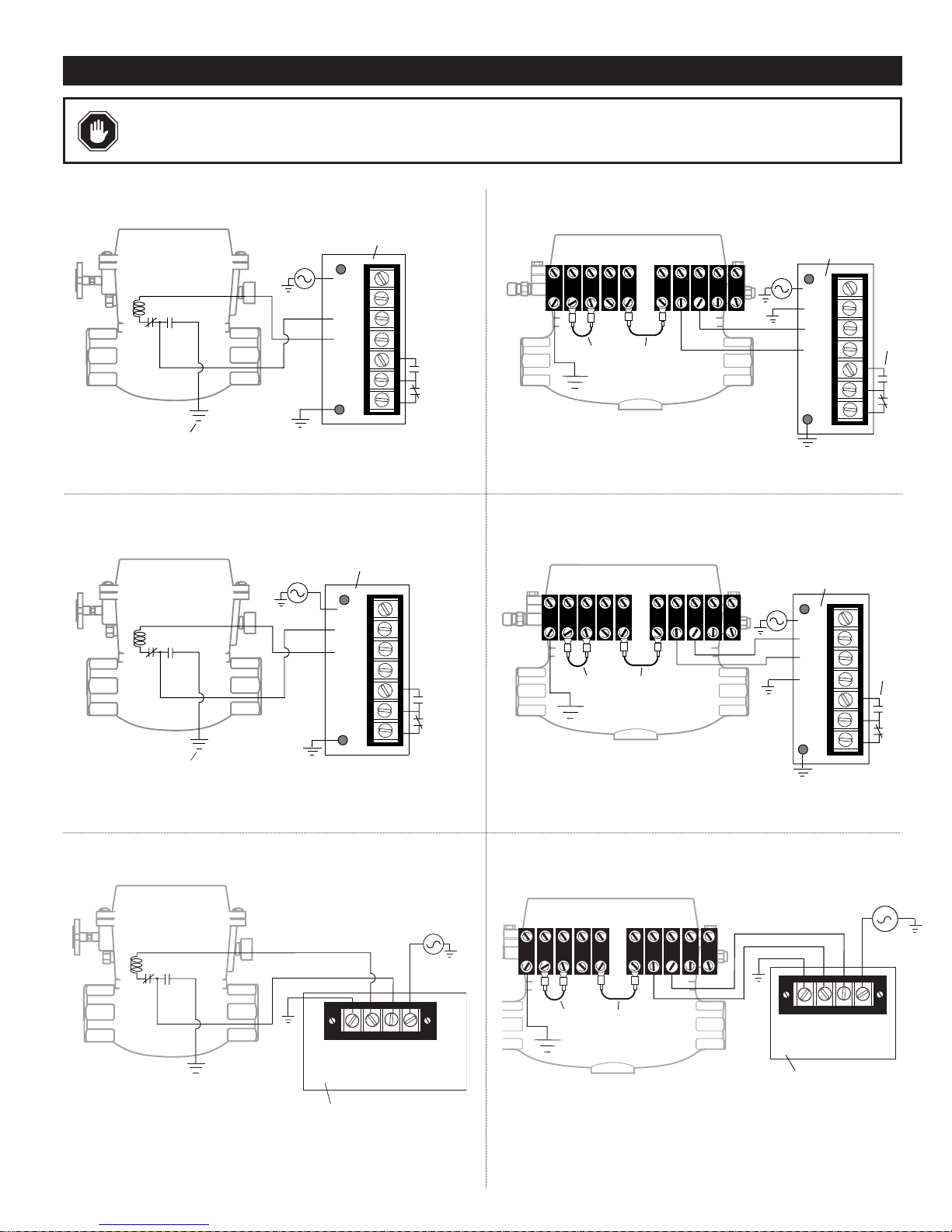
Tripping Power From Engine Ignition System or Battery
(Models available for magneto, CD ignition or 12/24 V battery)
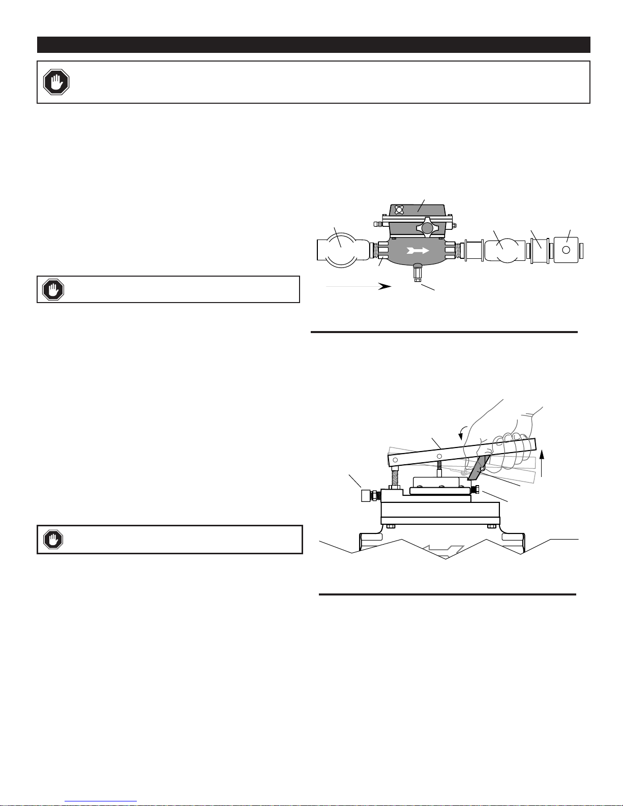
These fuel shut-off valves are semi-automatic devices for shutdown of
natural gas fueled engines. The standard valve opens by manual
operation of the reset handle. A latch in the upper body of the valve will
set and hold the valve open. At this point no electric power is used.
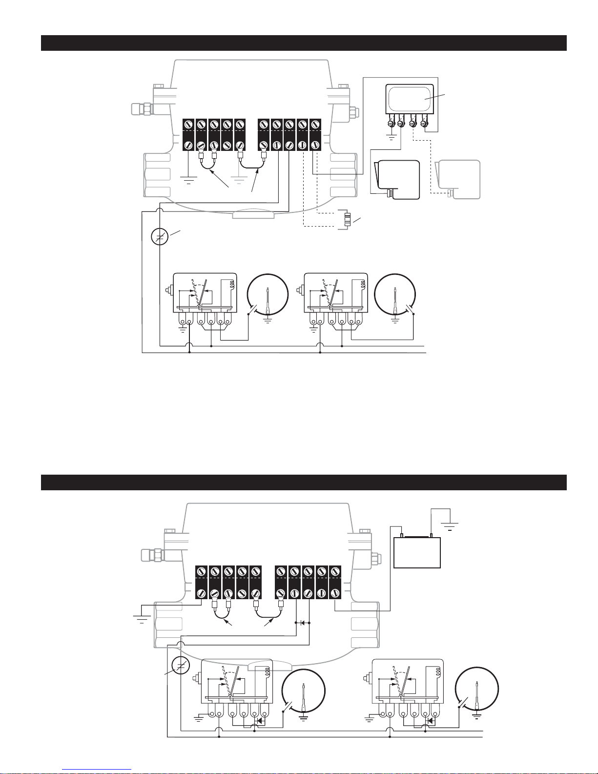
The electromagnetic coil is de-energized, the snap-switch(es) is SET.
If a SWICHGAGE®contact closes, a circuit is completed from power
through the snap-switch and coil. Now energized, the electromagnet
trips the latch, (latch can be tripped manually), the valve closes, and the
snap-switch resets. Power switches from the coil circuit to your choice
of an open line, an electrical ground, or an alarm. After tripping, the
vent seal opens, and on the M50 models, the open/close indicator (green
button) retracts to indicate that the valve is closed.
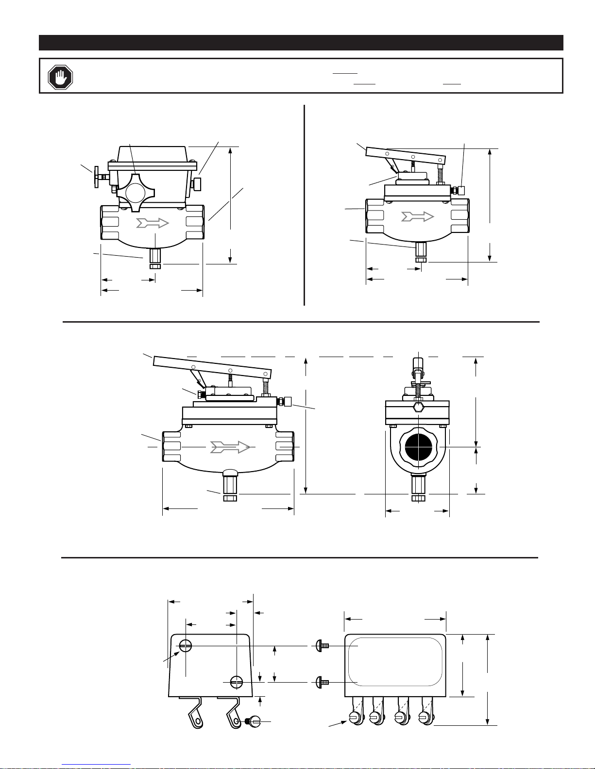
Valve body is sandcast aluminum. Optional cast steel for M5081 models.
M2582-P and M5180-P
MURPHY-NUMATIC™Pneumatic Version for Pressure
The M2582-P and M5180 pneumatically controlled valves can operate
from pressure, and are designed to open and close automatically or semi-
automatically (the supply can be air, oil or gas).
NOTE: If using oil as a pressure source, use a lightweight oil.
These valves will open on rising control pressure and close on
decreasing control pressure. M2582-P and M5180-P automatically open
at 2 psi (14 kPa) [0.14 bar] and fully open at 3 psi (21 kPa) [0.21 bar].
All models include a built-in lever to aid in opening the valve manually.
The M2582-P can be manually opened against inlet pressure of 80 psi
(552 kPa) [5.52 bar]. The M5180-P valve can be opened against inlet
pressure of 100 psi (689 kPa) [6.89 bar].
Standard models include an escape vent for gas trapped forward in the
line after shut-off.
M5081FS
Normally Energized Circuit
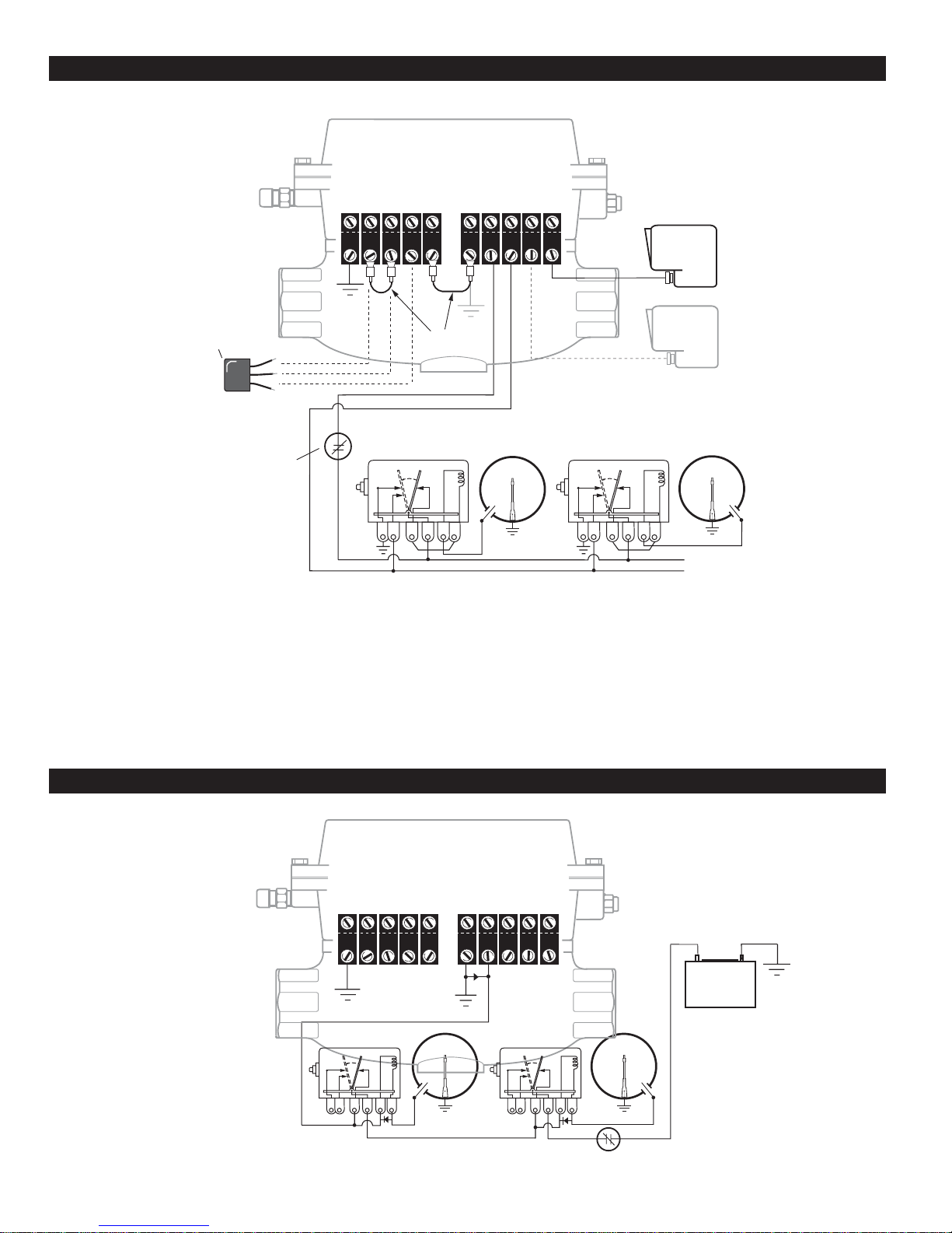
The M5081FS is manually opened, electrically latched open and tripped
by interrupting the coil power circuit.
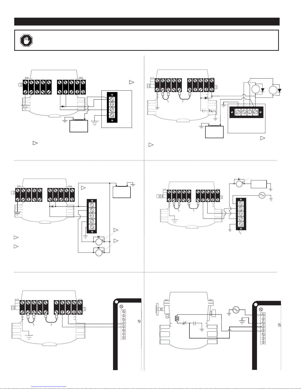
Magnetic Switch Adapter
As ignition systems wear from usage, their power output becomes less
and less. Ignition may not have the capacity to reliably trip the Fuel
Valve. Therefore, the use of a Magnetic Switch Adapter for CD
ignition systems is recommended. The Magnetic Switch Adapter is a
device that stores energy from the CD ignition to trip the Fuel Valve.
Three models are available:
65700053 (was 65020126): For use with negative ground ignitions
up to 240 VDC.
65700054 (was 65020127): For use with positive ground ignitions
up to 450 VDC.
65700055 (was 65020155): For use with negative ground ignitions
up to 450 VDC.
100 ohm, 2 watt Resistor
For Capacitor Discharge Ignitions that are specified to be grounded when
the valve closes, and a Magnetic Switch Adapter is in use. The resistor
must be connected in the system to prevent damage to the snap-switches
in the fuel shut-off valve (see typical wiring diagrams).
Diode Package
The Murphy diode package (65010065) is designed to allow the fuel shut-
off valve to be used with dual Magneto Ignition systems.
NOTE: All aluminum versions of the M5081 Series Fuel Valve carry
Canadian Registartion Number OC1476.2.
*M5081 model is CSA approved for Class I, Division 1, Groups C and D.
See Specifications on page 12.
GENERAL INFORMATION
Please read the following instructions before installing. A visual inspection of this product for damage during shipping is
recommended before mounting. It is your responsibility to have a qualified person install the unit and make sure installation
conforms with NEC and local codes.
M-7980N
Revised 11-02
Section 55
(00-02-0206)