Esu 54677 User manual

Instruction manual
2. Edition, December 20212. Edition, December 2021
P/N 05020-24306
54677 Smoke Unit „Dual“
ESU Smoke Unit

2
1. EU Declaration of Conformity................................. 2
2. WEEE Declaration..................................................... 2
3. Important hints – Please read this first!................. 3
4. General properties................................................... 3
5. Scope of delivery ..................................................... 3
6. Installation of the smoke generator ...................... 4
6.1 Filling the system ...........................................................4
6.2. Wiring ..........................................................................4
6.3. Connecting with LS 5 XL & LS 5 L decoder....................5
7. Programming the smoke generator....................... 6
7.1.1. Basic settings .............................................................6
7.1.2. Sound flow settings ...................................................7
7.1.3. Optimising functions................................................10
7.2. Cylinder steam function..............................................10
7.3. Firmware update with the LokProgrammer .................12
8. Support ................................................................... 12
9. Guarantee certificate............................................. 15
Content
1. EU Declaration of Conformity
ESU electronic solutions ulm GmbH & Co. KG, Edisonallee 29,
D-89231 Neu-Ulm, herewith declares in its sole responsibility that the
product complies in terms of
Product name: Smoke Unit „Dual“
Type number: 54677
with all relevant regulations regarding Electromagnetic Compatibility
(2004/108/EG). The following harmonized standards were applied:
EN 55014-1:2006 + A1:2009: Electromagnetic compatibility – Requi-
rements for household appliances, electric tools and similar apparatus
– Part 1: Emission
EN 55014-2:1997 + A1:2001 + A2:2008: Electromagnetic compatibi-
lity – Requirements for household appliances, electric tools and similar
apparatus – Part 2: Susceptibility.
2. WEEE Declaration
Directive (RoHS) and Waste Electrical and Electronic Equipment Direc-
tive (effective in the European Union and other European countries
with separate collection system).
This symbol displayed on the product, the packaging or in the do-
cumentation implies that this product may not be disposed of as
household refuse. Instead the product should be ta-
ken to the suitable waste disposal facility for recycling
of electrical and electronic products. By disposing of
the product in the correct manner you help to avoid
negative environmental effects and damage cause to
someone´s health that may be caused by inappropri-
ate disposal. Recycling of material will help to preserve our natural
resources. For further information regarding recycling of this product
please contact your local council, your collector of household refuse
or the shop where you purchased this product. All brands or trade-
marks are registered trademarks of the respective owners and are
not identified in all cases. One may not assume that due to a missing
trademark or identification that a term or a picture are not a registe-
red brand or trademark.

3
Important hints
3. Important hints – Please read this first!
We congratulate you to your purchase of an ESU smoke generator.
This manual aims to inform you step by step regarding the electri-
cal connection of this module.
In order avoiding any defects or damages please read this manual
carefully prior to installing the product!
•The smoke generator is exclusively to be used in electric model
trains and model train layouts. It may only be operated with the
components described in this manual.
•The smoke generator gets quite hot (more than 100°C). Avoid
touching it and choose the location for installing it in such a man-
ner that no damage can occur.
•Never turn the smoke generator upside down if its tank is filled.
Leaking oil may lead to burns.
•Only work on the electrical connections when the power is tur-
ned off.
•Adhere to the wiring principles when connecting the product as
presented in this manual.
•Protect the product against moisture and humidity.
•Wires may never touch any metal parts of the locomotive.
•For preventing short circuits please make sure there are no wires
squeezed when reassembling the locomotive.
4. General properties
The ESU smoke generator Dual for G and 1 Gauge models as well
as for larger 0 Gauge models generators realistic smoke and steam
clouds of your models. Both an exhaust steam and a cylinder
steam are integral to the housing. Two fan motors and two hea-
ting systems are separately controlled by the electronics subject to
state of movement. Sensors keep the desired heating temperature
independently of track voltage and fill level and prevents a burn
out in case of an empty tank.
The smoke generator is optimised for operating with our Lok-
Sound 5 XL and LokSound 5 L decoders. In combination with
these decoders the desired amount of smoke can be precisely
adapted to the sound flow. When connected to an ESU decoder
there is no need for any programming of the smoke generator.
5. Scope of delivery
With its dimensions of 69 x 33 mm (39 mm including the moun-
ting tabs) the smoke generator is relatively compact. The electro-
nics are separated from the mechanical part and connected with
a wire harness.
The following parts are contained in the scope of delivery:
•Smoke generator with separate circuit board (connected with wire
harness)
•Wire harness
•PVC tube (9 mm diameter) for cylinder steam

4
6. Installation of the smoke generator
Install the smoke generator at a suitable spot below the exhaust.
The spacing between the smoke generator and the opening of
the body should be as small as possible, but you should assure a
minimum distance of 1cm from the plastic locomotive body. Assu-
re a straight line for the exhaust for allowing condensed smoke to
drop back into the tank.
You may use the supplied silicone tube for establishing an airtight
connection between smoke generator and the opening in the
body. Shorten the silicone tubing as necessary.
6.1 Filling the system
The smoke distillate is filled into the tank through the exhaust ope-
ning. There is only one tank for both exhaust smoke and cylinder
steam. Only use ESU smoke distillate (part number 51990). Using
other liquids may cause damage to the paint finish, blocking the
system or destroying the heater unit due to accumulated residue.
Only activate the smoke function if somebody is present in well
aired (ventilated) rooms. The maximum filling capacity is 3.5ml.
This serves for about 10 minutes of operation.
Never exceed the maximum filling capacity of the system. If in
doubt, use a bit less rather than too much! The smoke generator
cannot be damaged even when the tank is empty!
Installation
Make sure the locomotive is on level ground when filling the tank,
never on gradient´, do not turn the locomotive sideways or upside
down! This avoids leaking distillate.
6.2. Wiring
Only use the supplied wire harness for connecting the smoke ge-
nerator. Simply plug the 6-pole plug directly on the circuit board
of the smoke generator.
The other end of the harness has a 4-pole plug as well as two
separate wires.
•The smoke generator receives the exhaust chuff pulses via the
green wire. The pulses may be supplied directly by a HALL sensor
or (preferably) be generated directly by the decoder.
•The smoke generator receives its commands via the yellow cable,
when connected to a LokSound 5 XL or LokSound 5 L decoder.
Connection to decoder
Figure 2: Wiring harness
Occupancy Colour
GND (ground) Black
not used Grey
not used Blue
U+ (Power supply) Red
AUX1 (Data transfer from the decoder) Yellow
Wheel sensor input Green
Figure 1: Smoke unit with connected electronics

5
6.3. Connecting with LokSound 5 XL & LokSound 5 L decoder
In this case the 4-pole plug is not needed. Cut it off and establish
the connection as shown in Fig. 3 respectively in Fig. 4.
The smoke generator receives its commands via the yellow wire.
Connection to decoder
This MUST be connected to the AUX1 output of the decoder.
The AUX1 output is the only one that can supply the appropriate
data for the smoke generator after it has been configured accor-
dingly (also refer to chapter 6.1).
Figure 4: Connecting to LokSound 5 L Decoder
Figure 3: Connecting to LokSound 5 XL Decoder

6
Programming Programming
7. Programming the smoke generator
There are several options for adjusting the performance of the
smoke generator. This helps to achieve optimum performance of
the smoke generator in conjunction with your model. Subject to
the decoder type different adjustments are required.
7.1. ESU LokSound 5 XL & LokSound 5 L decoder
You can configure the smoke generator in many ways to meet
your personal preference. This can only be done with the ESU Lok-
Programmer 53451 because some adjustments in the sound flow
are necessary. First load the desired sound project into the Lok-
Programmer followed by the individual adjustments. Sound and
smoke control work closely together and are both essential for
achieving optimal performance. As an example we illustrate the
process with the sound file S0010 (class 50). All required settings
have already been done. For all other sound projects you have to
adjust the required settings.
7.1.1. Basic settings
Initially the output AUX1 must be configured in such a way that it
provides the data for the smoke generator instead of functioning
as an ordinary function output.
•Select “AUX1[1]” in the register “Function Outputs and select
“Smoke generator with external circuit board”. Then click on the
last entry as shown in Fig. 5.
•Then the output connected to the green wire must be configured
such that an exhaust trigger is transmitted. In this example it is
AUX2.
•Select “Exhaust trigger” and adjust smoke and blower to the value
31 and the “Timeout” to 0. Fig. 6 shows the relevant settings.
Figure 5: Settings AUX1
Figure 6: Settings AUX2

7
Programming Programming
•Now you must assign the function button for triggering the smoke
generator in the register “Function Mapping”. Select the func-
tion “ESU Smoke generator” in the row of the desired function
button. The ex-works setting for most LokSound 5 decoders is
configured to F15.
7.1.2. Sound flow settings
The most important and comprehensive settings are found in the
“Sound” register. Adjust the desired heating temperatures and
the revs in the sound flow. Of course, for most projects this has
already been set ex-works, so you hardly need to change any of
these parameters.
First select sound slot 1 by double clicking it in the list of available
sound slots.
Figure 7: Function Mapping settings
Figure 8: Open Soundslot 1
8
Programming Programming
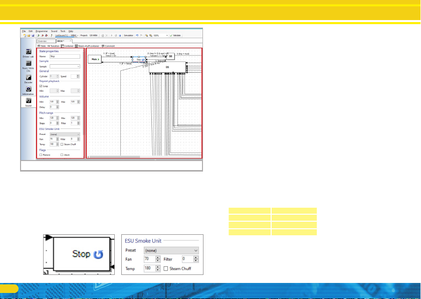
This opens a window similar to Fig. 9:
a) Conditions and transitions
b) Properties of the selected condition respectively transition
The properties shown on the left of part b) change subject to what
has been marked in the square at top right. Transitions are shown
as white rectangles. Mark the “Stop” condition with the mouse
as shown in the Fig. 9.
You will find the most interesting parameters in the chapter „ESU
Smoke generator”.
•Fan: Here you may adjust the revs of the fan motor. The higher the
value the faster turns the fan and the more smoke is ejected. The
value “255” means “full throttle” (maximum). Please determine
suitable values for your model. High fan revs usually also require
a higher temperature to assure that sufficient smoke is generated.
•Temperature: Here you may adjust the temperature in °C. Higher
values generate more smoke but also lead to a high thermal load
for the smoke generator. The maximum temperature of the smoke
generator is internally limited and is also subject to the mechanics.
The theoretically possible value of 255 °C will therefore not be
reached in practice.
•Filter: Here you may adjust how quickly the fan motor responds
to changes of the desired revs. The value 0 facilitates immediate
adaptation while higher values effect a soft transition. In some
case this may facilitate more realistic exhaust effects.
•Exhaust chuff: Enter this tick wherever smoke should be ejected.
Only if you enter a tick at these positions the LokSound decoder
will “instruct” the smoke generator to produce an exhaust chuff.
Otherwise smoke will continuously be ejected (Diesel mode).
It is necessary to enter meaningful values for every condition.
We recommend the following procedure:
STOP Condition:
Here low values should be entered, e.g.
Fan 59
Temperature 165
Filter 0
Exhaust chuff Not applicable
Figure 9: Soundslot 1 open
a)b)

9
Programming
SD Conditions (“Stop to Drive”), DS (“Drive to Stop”):
Here you may start with the following values:
Fan 42
Temperature 235
Filter 0
Exhaust chuff Not applicable
“Coast” as well as “DCX” conditions
Fan 42
Temperature 155
Filter 0
Exhaust chuff Not applicable
The actual speed steps are called Dx in all ESU projects. Some
sound projects contain D1 to D4, others go up to D8. These are
the normal exhaust chuffs.
Here you should experiment with the following values:
Fan 212
Temperature 220
Fan 0
Exhaust chuff Set
For acceleration steps A (mostly A1 to A4, sometimes to A8) we
recommend entering higher heating values and fan revs, e.g.
Fan 245
Temperature 235
Filter 0
Exhaust chuff Set
You may mark several conditions simultaneously by holding down
the shift button while marking the induvial squares one after the
other. If you now change the fan and temperature values, these
changes are valid for all currently marked conditions.
Figure 10: All D levels marked
10
Programming
If sound slot 2 is active in the list of available sound slots but is
marked in grey, there is no reason to be concerned. This means
that two sound channels are used for the exhaust chuff. A copy of
the smoke motor in Sound slot 1 will automatically be generated
and applied. Here you do not need to enter any changes.
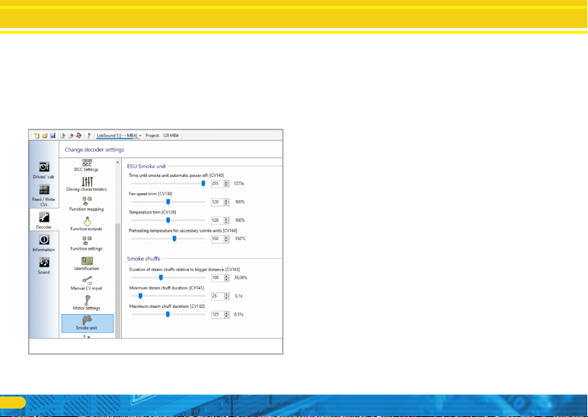
7.1.3. Optimising functions
In the final step you can optimize further options in the “Smoke
generator” register. Fig. 11 show all available options.
•Time until automatic switch off: Here you can set an automatic
switch-off time. Generally, a duration of about 10 minutes is
practical. This prevents excessive current draw when the tank is
empty. Whenever the smoke generator is turned off automatically
one must reactivate it by turning it off and then on again.
•Adaptation of the fan speed: Here you can adjust the fan speed
relative to the values set in the sound flow.
•Adaptation of the heating temperature: Here you can adjust the
temperature relative to the values set in the sound flow.
•Preheating temperature for secondary smoke generators: If so
desired, one can preheat the cylinder steam for achieving a faster
response. Please bear in mind that the preheating is active, until
the smoke generator is switched on and therefore draws extra
current.
•Duration of exhaust chuffs: Subject to wheel diameter and instal-
lation situation the exhaust chuffs may be a bit short. Increase the
value for triggering more powerful exhaust chuffs. The duration
is given in a ratio to their interval in %. A value of 50% triggers
exhaust chuffs whose duration is half of their interval.
•Minimum duration of exhaust chuffs: Regardless of how quickly
the pulses from the wheel sensor arrive, the duration of the ex-
haust chuffs will never fall below the value set here.
•Maximum duration of exhaust chuffs: Here you may adjust and
limit the duration of the exhaust chuffs to the desired value.
7.2. Cylinder steam function
For utilising cylinder steam you must first establish a mechanical
connection between the outlet of the smoke generator (in front,
at the bottom) and the opening on the locomotive.
Ideally the outlet is located between the cylinders. Some silicone
tube is supplied with the smoke generator.
Figure 11: Smoke generator settings

11
Programming
Now all you need to do is set appropriate values for heating tem-
perature and fan speed in the “Cylinder blow-out” register. In our
example this is entered in sound slot 9 “Cylinder blow-out”.
The LokSound decoder “assumes” in case of sound slot greater
than 4 that this must be cylinder steam and transmits the re-
levant commands to the smoke generator. The number of the
sound slot facilitates triggering the corresponding smoke gene-
rator. Sound slots 1 and 2 control the main exhaust, all sound
slot 4 or higher control cylinder steam.
Finally, please make sure that you write the CV values AND the
sound to the decoder once again. The entries regarding the smoke
generator will only be written in conjunction with the sound data.
Figure 12: Cylinder steam outlet
Cylinder steam
outlet
Figure 13: Soundslot 9 Cylinder steam smoke generator settings
12
Support
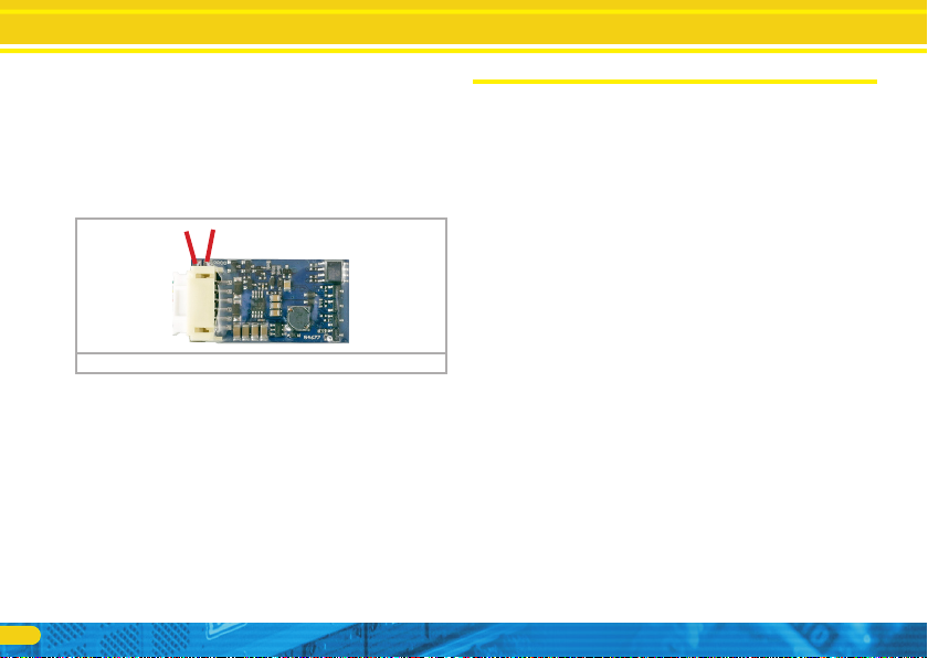
7.3. Firmware update with the LokProgrammer
Of course, the firmware of ESU smoke generators can be updated
with the LokProgrammer. However, the smoke generator must be
removed from the model and directly connected to the LokPro-
grammer. There are two separate solder points for this purpose.
They are marked with “PROG”. Fig. 14 shows where they are lo-
cated. These two outputs must be wired to the LokProgrammer.
Disconnect all other wires to the decoder by removing the white
plug. The connection to the smoke generator does not have to
be separated.
Figure 14: 54677 Solder connections for LokProgrammer
8. Support
Should you have questions regarding your smoke generator to
which you have not found the right answer in this manual please
first contact your hobby shop. The people there are your compe-
tent contact for all questions relating to model trains. In difficult
cases, you can contact us directly. Look first on our website under
«Support / FAQ» to see whether the question has already been
answered. If this is not the case, we ask you to make these availab-
le to us either in our support forum or to contact us by e-mail. We
also provide a telephone hotline, which should only
be used in the case of really special requests.
For Germany
by phone: +49 (0) 731 - 1 84 78 - 106
Tuesday & Wednesday
from 10.00 to 12.00 o‘ clock
by Fax : +49 (0) 731 - 1 84 78 - 299
by E-Mail: www.esu.eu/kontakt
by mail: ESU GmbH & Co. KG
Edisonallee 29
D-89231 Neu-Ulm
www.esu.eu
For USA, Canada, Australia
by phone: +1 570-980-1982
Tuesday & Thursday
from 8am to 4pm (EST)
by Fax : +1 866-591-6440
by mail: ESU LLC
1304 Jordan Ave
Montoursville PA 17754
www.loksound.com

13
Notices

14
Notices
Copyright 1998 - 2021 by ESU electronic solutions ulm GmbH & Co KG. Irrtum, Änderungen die dem technischen Fortschritt dienen, Liefermöglichkeiten und alle sonstigen
Rechte vorbehalten. Elektrische und mechanische Maßangaben sowie Abbildungen ohne Gewähr. Jede Haftung für Schäden und Folgeschäden durch nicht bestimmungs-
gemäßen Gebrauch, Nichtbeachtung dieser Anleitung, eigenmächtige Umbauten u. ä. ist ausgeschlossen. Nicht geeignet für Kinder unter 14 Jahren. Bei unsachgemäßem
Gebrauch besteht Verletzungsgefahr.
Märklin® und mfx® sind eingetragene Warenzeichen der Firma Gebr. Märklin® und Cie. GmbH, Göppingen. RailCom® ist ein eingetragenes Warenzeichen der Firma Lenz®
Elektronik GmbH, Gießen. RailComPlus® ist ein eingetragenes Warenzeichen der Firma Lenz® Elektronik GmbH, Gießen.
LocoNet™ ist ein eingetragenes Warenzeichen der Fa. Digitrax, Panama City, USA.
Alle anderen Warenzeichen sind Eigentum ihrer jeweiligen Rechteinhaber.
ESU electronic solutions ulm GmbH & Co. KG entwickelt entsprechend seiner Politik die Produkte ständig weiter. ESU behält sich deshalb das Recht vor, ohne vorherige
Ankündigung an jedem der in der Dokumentation beschriebenen Produkte Änderungen und Verbesserungen vorzunehmen.
Vervielfältigungen und Reproduktionen dieser Dokumentation in jeglicher Form bedürfen der vorherigen schriftlichen Genehmigung durch ESU.

15
Guarantee certificate
9. Guarantee certificate
24 months warranty from date of purchase
Dear customer,
Congratulations on purchasing this ESU ECoS command station. This quality product was manufactured applying the most advanced produc-
tion methods and processes and was subject to stringent quality checks and tests.
Therefore ESU electronic solutions ulm GmbH & Co. KG grants you a warranty for the purchase of ESU products that far exceeds the national
warranty as governed by legislation in your country and beyond the warranty from your authorised ESU dealer.
Manufacturer’s warranty of 24 months from date of purchase.
Warranty conditions:
This warranty is valid for all ESU products that have been purchased from an authorised ESU dealer.
Any service, repair or replacement under this warranty requires proof of purchase. The filled in warranty certificate together with the receipt
from your ESU dealer serves as proof of purchase. We recommend keeping the warranty certificate together with the receipt.
In case of a claim please fill in the enclosed failure report card as detailed and precise as possible and return it with your faulty product.
Please use the appropriate postage when shipping to ESU.
Extend of warranty / exclusions:
This warranty covers free of charge repair or replacement of the faulty part, provided the failure is demonstrably due to faulty design, manu-
facturing, material or transport. Any further claims are explicitly excluded.
The warranty expires:
•In case of wear and tear due to normal use.
•In case of conversions of ESU – products with parts not approved by the manufacturer.
•In case of modification of parts.
•In case of inappropriate use (different to the intended use as specified by the manufacturer).
•If the instructions as laid down in the user manual by ESU electronic solutions ulm GmbH & Co. KG were not adhered to.
There is no extension of the warranty period due to any repairs carried out by ESU or replacements.
You may submit your warranty claim either with your dealer or by shipping the product in question with the warranty certificate, the receipt
of purchase and the fault description directly to ESU electronic solutions ulm GmbH & Co. KG at:
ESU GmbH & Co. KG
- Guarantee Section -
Edisonallee 29
D-89231 Neu-Ulm

16
1. Personal data (Please write in block letters)
Name:...................
Street:...................
ZIP/City: ................ ||||||
Country: ...............
Email:....................
Phone: ..................
Date:.....................
Signature: .............
2. Error
No Function (please describe the error in more detail)
3. Error description (use extra page if needed)
4. Receipt
Please enclose your receipt / invoice. Otherwise no warranty possible!
5. Additional information: 6. Your retailer:
Retailer´s stamp or address
Trouble shooting sheet
Table of contents
Popular Portable Generator manuals by other brands

DTI Dyna Technology
DTI Dyna Technology Winco W3000H Installation and operator's manual

Wagan
Wagan SOLAR e POWER CASE 800 user manual

Fabco Power
Fabco Power HYDRO 300CX-4.5-60HZ-G instruction manual

GENTRON
GENTRON 950W Series owner's manual

CAMPAGNOLA
CAMPAGNOLA POWER 12 Use and maintenance manual

Rigol
Rigol DSG3000 Series user guide


