ESY Sunhome ESYSUNHOME 5KWH+ Instruction Manual

ESYSUNHOME ESS BATTERY SYSTEM
ESY SUNHOME CO., LTD
ESY SUNHOME CO., LTD
User Guide & Installation Manual
Made in China
Website﹕ www.esysunhome.com
Phone: +86 (0)755 8522 9087
Address: 101, Building 6, No. 5-2, Inner Ring Road, Shanxia Community,
Pinghu Street, Longgang District, Shenzhen, China.

8 Batte Maintenance
8.1 Staup and Shutdown Procedure
8.2 BMS-STM8S-TI
8.2.1 BMS-STM8S-TI software connection
8.2.2 BMS-STM8S-TI functions operation
8.3 Maintenance Instructions
9 After-sales Seice
19
19
19
20
20
22
22
Table of Contents
Mission:
To provide safe and high quality new energy products (batteries and power supplies) for eve
family.
Vision:
Take the sun home.
1 Precautions
1.1 General Statement
1.2 Requirements for Installation and
Maintenance Personnel
1.3ImpoantSafetyInformation
2 SafetyPrecautionsforUse
3SafeTranspoationandStorage
3.1BatteTranspoation
3.2BatteStorage
4 Appearance
4.1OutlineDimensions
4.2NameplateIdentication
4.3PoDescription
4.4NoACconnectiononbatte
4.5 Batte Isolation Device Description
5 Product Parameters
5.1 Parameters of the Batte
5.2ModuleParameters
6 Circuit Structure Schematic
7 Preparation Before Installation
7.1PackingListofBatte
7.2BaseofBatte
7.3PreparationbeforeInstallations
7.3.1PreparationofInstallationTools
7.3.2SelectionoftheInstallationEnvironment
7.3.3 Installation Safety Precautions
7.3.4SelectionofInstallationLocations
7.4Installation
7.4.1Location
7.4.2Drilling
7.4.3BracketInstallation
7.4.4OneBatteInstallation
7.4.5StackingofMultipleBatteries
7.4.6Batte Eahing
7.5DCConnectionInstructions
7.6BatteandInveerCommunication
7.7HowtoSetUpBatteMonitoring
01
01
01
02
02
03
03
03
03
03
04
05
07
07
07
07
07
08
09
09
09
10
10
11
12
13
14
14
15
15
16
17
17
18
18
19
Core Values:
Unity and hard work;
Pragmatic and far-reaching;
Innovative research and development;
Scientic and intelligent manufacturing;
Creating value for customers;
Creating oppounities;
Contributing to society.
ESY SUNHOME staed out as a lithium batte business, powered by cutting-edge batte protection
systems and a procient Research & Development team. The founder, Mr. Lee, recognized the absence
of energy storage choices available to households worldwide and was enthusiastic about combining
photovoltaic energy storage solutions with lithium batteries. With this vision in mind, the team
embarked on the development and testing of PV home energy storage products, forming an ecient,
highly qualied team of Research & Development, manufacturing, and quality control professionals
with distinguished backgrounds in various elds of technology. After two years of intensive eo, the
team successfully developed and tested PV home energy storage products, resulting in the ocial
launch of the HM6 series storage system products on Janua 14th, 2023. ESY SUNHOME now has
branches in Sydney, Australia and Munich, Germany, with a long-term objective of becoming a
global brand.
2 Safety Precautions for Use
Before conducting any work, carefully read all safety instructions and always adhere to them
when handling or using the batte. Failure to comply with the preventive measures described
in this section may result in severe personal inju or propey damage.
02
声明
01
1 Precautions
NOTE
Professionals: Professionals refer to individuals who have received training or have experience
in equipment operation and possess professional knowledge of potential hazards and their
severity in equipment installation, operation, and maintenance.
Trained personnel: refer to the personnel who have received technical training or have the
necessa experience, and are aware of possible hazards in some operations and able to take
protective measures to minimize hazards to themselves and others.
Operators: refer to the personnel who have access to devices except trained personnel and
professionals.
1.1 General Statement
Statement
This manual applies to the ESYSUNHOME ESS Batte Models:
ESYSUNHOME 5KWH+
ESYSUNHOME 10KWH+
ESYSUNHOME 15KWH+
ESYSUNHOME 20KWH+
ESYSUNHOME 25KWH+
ESYSUNHOME 30KWH+
Please read this manual carefully and strictly adhere to all safety instructions during installation,
operation, and maintenance. ESY SUNHOME will not be liable for any consequences arising from
noncompliance with the general safety requirements or safety standards of design, production
and use.
It is crucial to use this product under the specied design conditions, as any damage to pas,
personal inju, or propey loss resulting from improper usage will not be covered by the warranty.
In addition, during installation, usage, and maintenance, all local laws and regulations must be
obseed. The safety instructions in this manual are supplementa to local laws and regulations.
During the installation and debugging of the batte, please use dedicated charging and
discharging equipment.
ESY SUNHOME reserves the right not to assume any responsibility for consequences arising
from the following:
Damage caused during transpoation;
User does not meet the national standards to install, ret or use our device;
Noncompliance with the installation and use instructions outlined in this manual;
Operation under harsh conditions that are not specied in this manual;
Failure or damage caused by installation, repair, modication, or disassembly by non-authorized seice personnel;
Energy storage system failure or damage caused by the use of non-standard components or software or those that
are not provided by our company;
Noncompliance with relevant international standards for design, installation and use;
Device damage caused by abnormal natural conditions (force majeure such as lightning strikes eahquakes, re
and storms).
Expiation of free warranty of the product and its pas;
The personnel to be dispatched for installing or maintaining ESY SUNHOME’s devices are fully trained and
knowledgeable of all safety precautions and capable of peorming all operations correctly.
Safety facilities must be dismantled and inspected by professionals.
Only professionals or authorized personnel are allowed to replace equipment or components (including device
software).
Device installation, operation and maintenance must be carried out by professionals or trained personnel.
1.2 Requirements for Installation and Maintenance Personnel
1.3 Important Safety Information
Before device installation, operation and maintenance, please read this manual carefully.
Make sure that the product is eectively grounded before operation. The grounding resistance
should be less than 0.1Ω.
Batte installation must be carried out according to this instruction manual. During operation, comply with the
relevant signs and symbols on the equipment.
The batte terminals may be live during operation. If the batte is not connected, cover it with insulating material
inside a protective cover for protection.
If the energy storage system, consisting of the batte, needs to be connected to the grid for power supply, it must
obtain approval from the local power depament or comply with the relevant regulations of the user's count and
local laws. Grid connection should be peormed by qualied personnel.
Use a d powder extinguisher in case of re. Do not use a liquid extinguisher.
When installing the batte, installation personnel must strictly adhere to the installation standards specied in
AS/NZS 5139.
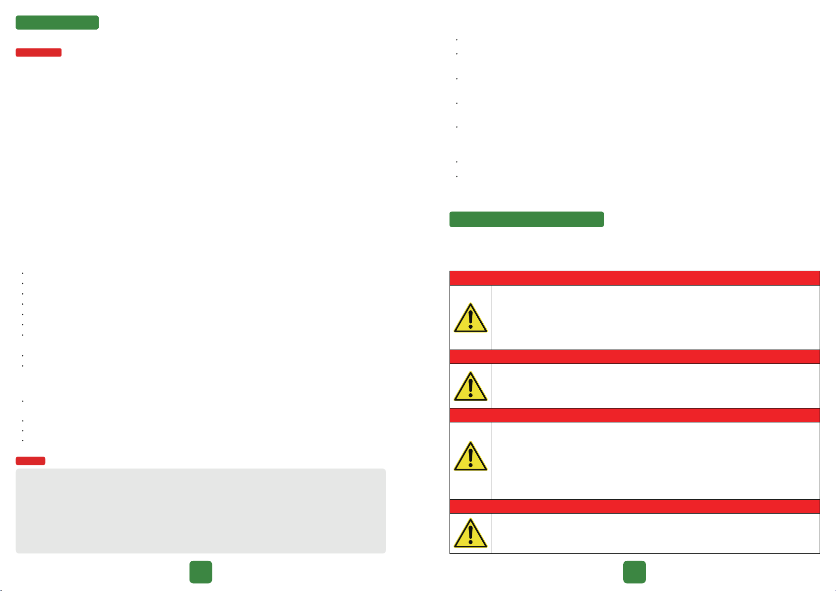
Fire hazard!
Do not place the batte near heat sources, such as direct sunlight, replace, non-insulated walls
exposed to sunlight, hot water, or heaters. Keep ignition sources like sparks, ames, and smoking
materials away from the batte.
Electric shock hazard!
Do not dismantle the batte.
Do not handle the batte or use wet tools.
Do not immerse the batte in water or expose it to moisture or liquid.
Keep the batte out of reach of children and animals.
Wear appropriate clothing, protective equipment, and gloves to prevent direct contact with DC voltage.
Use insulated tools when working with the batte.
Remove metal jewel before dealing with the DC circuit.
Gas hazard!
Damaged batteries may release hazardous substances and ammable gas mixtures. Even if you are a
qualied electrician, do not attempt to repair the batte.
Explosion hazard!
Do not apply any excessive force to the batte.
Do not subject the batte to mechanical damage (such as puncturing, deforming, stripping, etc.).
Do not heat the batte or expose it to re.
Do not install the batte in potentially explosive environments.
Do not submerge the batte in water or other liquids.

3.2 Battery Storage
If the batte is not installed immediately, it needs to be stored properly. When storing the equipment,
use the original packaging and store it in a cool, d, and well-ventilated area to prevent equipment
damage due to moisture.
This product should be stored at an ambient temperature of -10°C to 35°C for no more than 6 months.
The relative humidity during storage should be between 0% to 95% Rh. Store the batte in a clean and
d place, avoiding exposure to direct sunlight and rain. The storage location must be free from harmful
gases, ammable/explosive products, and corrosive chemicals. Avoid mechanical impact, high voltage,
high-intensity magnetic elds, and direct sunlight on the batte. Pay attention to harsh environments
such as sudden cooling/heating and collisions to prevent damage to the batte.
Packaged batte modules should not be stacked more than 5 layers high, and direct stacking of
unpackaged batteries is strictly prohibited.
If the batte is stored for more than 3 months under specied conditions, it needs to be charged
once until the system SOC reaches 50% to 80%. Please use our rechargeable products for charging.
Failures and hazards caused by charging and discharging with other equipment are not covered
under our warranty. For storage with SOC at 50%, a charge-discharge maintenance should be
peormed within 6 months to prevent irreversible capacity loss. If storage with SOC at 50% exceeds
9 months without charge-discharge maintenance, any capacity loss or other defects caused to the
batte will be considered as a waiver of warranty by our company.
4 Appearance
4.1 Outline Dimensions
Battery Dimensions
305±0.5 mm
220±0.5 mm
600±0.5 mm
Base Dimensions
4.2 Nameplate Identification
03 04
3 Safe Transpoation and Storage
3.1 Battery Transportation
When transpoing the batte, it must be packed in the original packaging to ensure the safety
of the equipment during transpoation.
Upon receiving the goods, please inspect the external packaging of the batte and then open
the box for a comprehensive inspection.
If any damage to the batte occurs during transpoation, please notify the shipping company.
The shipping company is responsible for any equipment damage caused during transpoation.
If necessa, seek assistance from the installer or manufacturer.
When handling batte weighing 50 kg or more, please use appropriate equipment or work
together with multiple people.
When storing the equipment, please use the original packaging and store it in a cool, d, and
well-ventilated area to prevent damage caused by moisture.
Pay attention to safety.
Pay attention to high suace temperature.
Be cautious of electric shock.
Compliant with CE safety ceication standards.
This product is in compliance with IEC 62040 ceication
standards.
This product is in compliance with RCM ceication standards.
Professional recycling is required.
Please read this manual before using the product.
Prior to attempting any repair, electrical installation or accessing
any live pas, make sure that the power supply is cut o and wait
for 5 min until internal capacitors are discharged to a safe voltage.
ESYSUNHOME: brand
5KWH+: model, indicating that the batte specication is
5KWh
305±0.5 mm
28±0.5 mm
600±0.5 mm
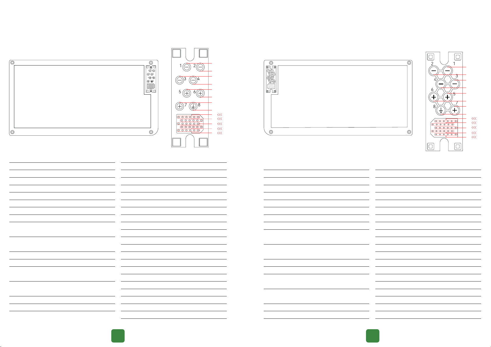
4.3
Po Description
Schematic diagram of top port arrangement for battery Schematic diagram of bottom port arrangement for battery
05 06
S/N
01
02
03
04
05
06
07
08
09
10
11
12
13
14
15
16
17
Mark
PACK-
PACK-
PACK-
PACK-
PACK+
PACK+
PACK+
Ground wire
RS485-B2
RS485-A2
GND
GND
SW-air switch
SW-air switch
NC
NC
NC
Purpose
Batte cathode
Batte cathode
Batte cathode
Batte cathode
Batte anode
Batte anode
Batte anode
Ground wire of the chassis
Batte and power supply
communication po
Batte and power supply
communication po
Ground wire
Ground wire
Signal cable for enabling
batte discharge
Signal cable for enabling
batte discharge
Reseed inteace
Reseed inteace
Reseed inteace
Purpose
Reseed inteace
Reseed inteace
Reseed inteace
Reseed inteace
Reseed inteace
Reseed inteace
Reseed inteace
Reseed inteace
Reseed inteace
Reseed inteace
Reseed inteace
Reseed inteace
Reseed inteace
Reseed inteace
Reseed inteace
Reseed inteace
Reseed inteace
Reseed inteace
Reseed inteace
Reseed inteace
Reseed inteace
S/N
18
19
20
21
22
23
24
25
26
27
28
29
30
31
32
33
34
35
36
37
38
Mark
NC
NC
NC
NC
NC
NC
NC
NC
NC
NC
NC
NC
NC
NC
NC
NC
NC
NC
NC
NC
NC
S/N
01
02
03
04
05
06
07
08
09
10
11
12
13
14
15
16
Mark
PACK-
PACK-
PACK-
PACK-
PACK+
PACK+
PACK+
Ground wire
RS485-B2
RS485-A2
GND
GND
SW-air switch
SW-air switch
RS485-A2
RS485-B2
Purpose
Batte cathode
Batte cathode
Batte cathode
Batte cathode
Batte anode
Batte anode
Batte anode
Ground wire of the chassis
Batte and power supply
communication po
Batte and power supply
communication po
Ground wire
Ground wire
Signal cable for enabling
batte discharge
Signal cable for enabling
batte discharge
Batte and power supply
communication po
Batte and power supply
communication po
Purpose
Reseed inteace
Ground wire
Communication Inteace
Communication Inteace
Communication Inteace
Communication Inteace
Reseed inteace
Reseed inteace
Reseed inteace
Ground wire
Communication Inteace
Communication Inteace
Communication Inteace
Communication Inteace
Reseed inteace
Reseed inteace
12V+
12V+
Reseed inteace
Reseed inteace
Ground wire
Ground wire
S/N
17
18
19
20
21
22
23
24
25
26
27
28
29
30
31
32
33
34
35
36
37
38
Mark
NC
GND
CAN-H2
CAN-H2
CAN-L2
CAN-L2
NC
NC
NC
GND
CAN-H1
CAN-H1
CAN-L1
CAN-L1
NC
NC
12V+
12V+
NC
NC
GND
GND
04
02
08
06
05
07
01
03
14 09
20 15
26 21
32 27
38 33
01
02
03
04
05
06
07
08
09 14
15 20
21 26
27 32
33 38

4
20.48
19.456
4.864
400
﹙600±2)x﹙305±2)x﹙908±2)
207±1
4864
95
4864
95
(16S)4P
5 Product Parameters
07 08
6 Circuit Structure Schematic
Batte
Voltage I2C
Control signal
Temperature
Balancing
Power circuit
MCU
AFE
Communication inteace
Discharge enable control switch
Multifunctional button
Load/charger detection
B- P-/C-
P+/C+
Current and sho circuit
sensing circuit
Discharge MOSFET
switch
Charging MOSFET
switch
MOS driver circuit
Pre-discharge
control
Charging current
limiting circuit
4.4 No AC connection on battery
The batte does not possess an alternating current (AC) inteace; it has a direct current (DC) inteace. There are three
terminals labeled PACK+ and four terminals labeled PACK-. On the top and bottom of the batte, there are dedicated
GP38 connectors that are directly connected. Please refer to the batte po diagram.
The connection between the batte and the inveer is in the form of direct current (DC). The inveer's AC inteace is
linked to the grid and the backup power source.
4.5 Battery Isolation Device Description
The positive output terminal P+ of the batte is controlled by the discharge control terminal SW. When there are no
external connections, P+ does not output any power. Power output from the batte only occurs when the external
control box or inveer is installed, and the batte switch is turned on.
Both batte terminals, P+ and P-, are isolated and covered with silicone sleeves. The protective sleeves are removed
during installation, and there is no voltage output during the installation or removal process.
Batteries are intended to be installed with ESYSUNHOME HM6 which has an integrated circuit breaker for isolating the
batte.
ESYSUNHOME ESS Battery Models
51.2
IFpP
40.8~57.6
56.8
57.6
40.8
95 %
3~55
-20~58
IEC 62619﹐ ISO 13849, IEC/EN 62040-1, CEC+RCM
IEC 61000-6-1, IEC/EN 61000-6-3
IP66
Ⅰ
120 months
China
5.1 Parameters of the ESYSUNHOME ESS Battery Models
Model
Nominal Voltage (Vd.c.)
Batte Type
Voltage Range (V)
Charging Voltage Declared by Manufacturer (V)
Upper limit Charging Voltage (V)
Discharging Cut o Voltage (V)
Depth of Discharge
Standard Temperature Range for Charging (℃)
Standard Temperature Range for Discharging (℃)
Standards
EMC Standards
Ingress Protection Rating
Protection Class
Warranty
Count of Manufacture
5.2 Module Parameters
Number of Batteries
Batte Capacity (kWh)
Usable Capacity (kWh)
Rate DC Power ﹙kW﹚
Rated Capacity ﹙Ah)
Size (LxWxH mm)
Weight (kg)
Max. Continuous Charging Power ﹙W﹚
Max. Continuous Charging Current (A)
Max. Continuous Discharging Power ﹙W﹚
Max. Continuous Discharging Current (A)
Conguration
Model ESYSUNHOME 5KWH+ ESYSUNHOME 10KWH+
1
5.12
4.864
4.864
100
﹙600±2﹚x﹙305±2﹚x﹙248±2﹚
57±1
4864
95
4864
95
16S
2
10.24
9.728
4.864
200
﹙600±2﹚x﹙305±2﹚x﹙468±2﹚
107±1
4864
95
4864
95
(16S)2P
3
15.36
14.592
4.864
300
﹙600±2﹚x﹙305±2﹚x﹙688±2﹚
157±1
4864
95
4864
95
(16S)3P
ESYSUNHOME 15KWH+
Number of Batteries
Batte Capacity (kWh)
Usable Capacity (kWh)
Rate DC Power ﹙kW﹚
Rated Capacity ﹙Ah)
Size (LxWxH mm)
Weight (kg)
Max. Continuous Charging Power ﹙W﹚
Max. Continuous Charging Current (A)
Max. Continuous Discharging Power ﹙W﹚
Max. Continuous Discharging Current (A)
Conguration
Model
5
25.6
24.32
4.864
500
﹙600±2)x﹙305±2)x﹙1128±2)
257±1
4864
95
4864
95
(16S)5P
6
30.72
29.184
4.864
600
﹙600±2)x﹙305±2)x﹙1348±2)
307±1
4864
95
4864
95
(16S)6P
ESYSUNHOME 20KWH+ ESYSUNHOME 25KWH+ ESYSUNHOME 30KWH+

09 10
2Expansion screw gaskets
Inner diameter: 5mm;
outer diameter: 12mm;
SUS304 gasket
7.2 Base of Battery
600 mmx305 mmx44.1 mm
Silicone, black, matte,
110 mmx39.9 mmx9 mm
(installed on the base)
PM4*8mm
1
1
4
Waterproof
connector cover
Bracket
Bracket
mounting
screws
Name Specifications Quantity Schematic Diagram
7 Preparation Before Installation
7.1 Packing List of Battery
1
2
1
2
4
2
Battery
Fixing angle iron screws
Waterproof connector cover
Corner angle irons
Handlebar screws
Expansion tubes with screws
Name Specifications Quantity Schematic Diagram
M4x8 mm
5KWH+ residential
energy storage battery
Silicone, black, matte,
110 mmx39.9 mmx9 mm
L60.5x32x25 mm
M4x30 mm flange hex screws
6 mmx40 mm
7.3 Preparation before Installation
7.3.1 Preparation of Installation Tools
Tools and Descriptions
Spirit level Marker
Electric drill with φ6
Hammer
Screwdriver
Phillips
PH1
Allen
M2
Slotted
SL2.5
Diagonal pliers
Utility knife Crimping pliers
Network cable
crimping pliers
Installation
Type
Safety
Safety gloves Dust mask Goggles
Ruler
Stripping pliers
Open-end wrench
S=7mm
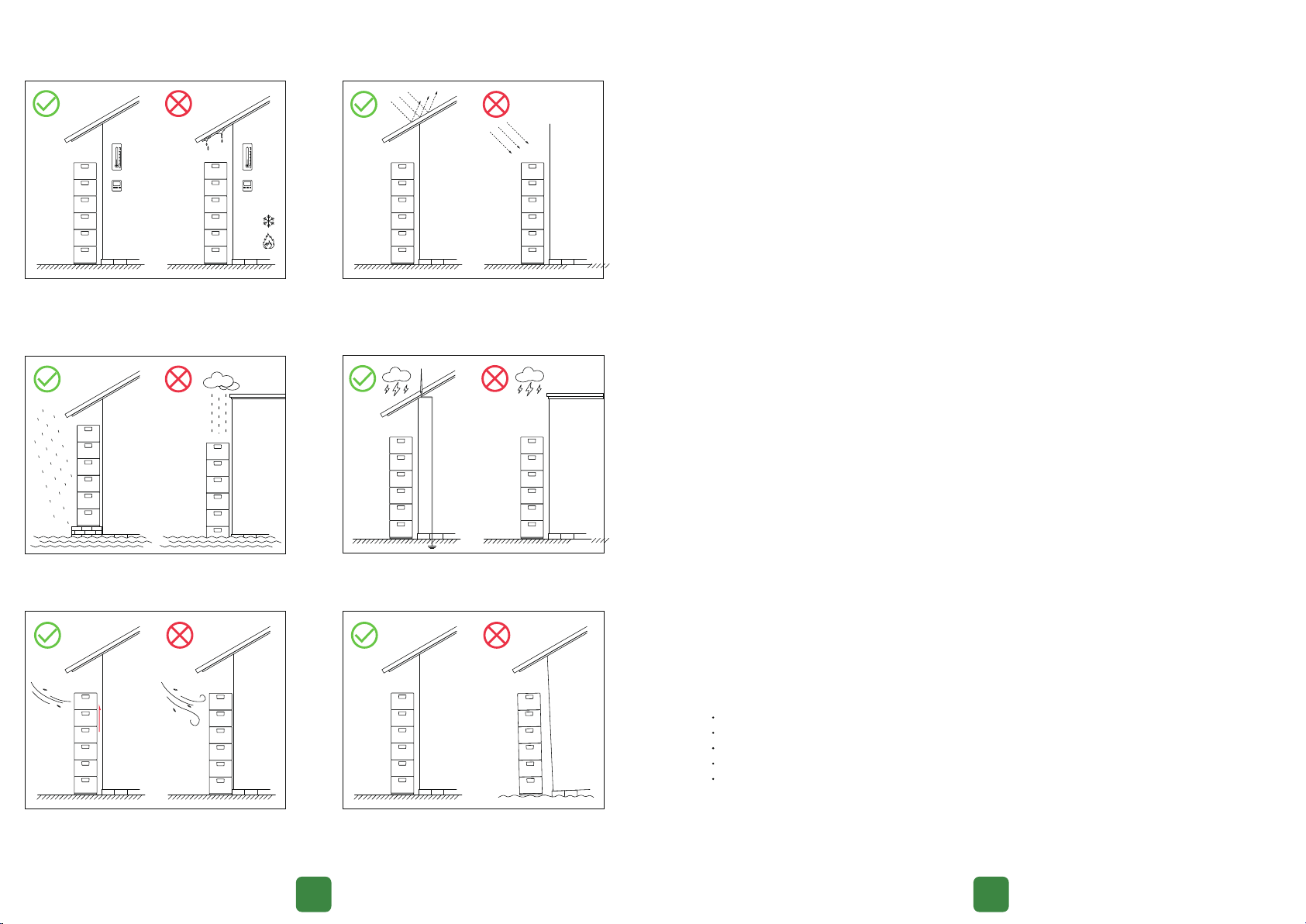
7.3.2 Selection of the Installation Environment
Please select the site according to the relevant requirements.
Do not install it in a wet place or in water. Do not install it in areas prone to lightning
strikes.
This product is self-cooled. To ensure proper
heatdissipation, please install it in a
well-ventilated place.
For stability, the product should be installed
on solid and at ground, with the wall being
perpendicular to the ground.
The ambient temperature should be -20 ℃ to
58 ℃and the relative humidity should be 0%
to 100% (no condensation).
-20℃
≤100%
58℃
≤-20℃
≥100%
≥58℃
It can be installed outdoors, but must not be
directly exposed to sunlight.
11 12
7.3.3 Installation Safety Precautions
The installation and use environment of lithium batteries must comply with relevant international,
national, and local standards, as well as local laws and regulations.
Ensure that the battery is not accessible to children and is kept away from areas of daily work or
living, including but not limited to: offices, bedrooms, living rooms, music rooms, kitchens, studies,
game rooms, home theaters, sunrooms, bathrooms, laundry rooms, and attics.
When installing the battery in a garage, keep it away from the driveway. It is recommended to
install the battery on a wall higher than the bumper to prevent collisions.
For basement installations, maintain good ventilation. Do not place flammable or explosive
materials around the battery. It is recommended to install the battery on a wall to avoid contact
with water.
Install the battery in a dry and well-ventilated environment and secure it on a solid and flat
surface.
Install the battery in a concealed location or install a canopy above it to protect it from direct
sunlight or rain.
Install the battery in a clean environment without strong infrared radiation, organic solvents, and
corrosive gases.
For areas prone to natural disasters such as floods, earthquakes, and typhoons/hurricanes,
appropriate installation precautions should be taken.
Keep the battery away from ignition sources. Do not place any flammable or explosive materials
around the battery.
Keep the battery away from water sources such as faucets, drains, sprinklers, etc., to prevent water
ingress.
Do not install the battery in easily accessible locations, as the enclosure and heat sink temperature
can be high when the battery is in operation.
To prevent overheating, ensure that the vents and cooling system are not blocked when the
battery is in operation.
Do not expose the battery to flammable or explosive gases or smoke. Do not perform any
operations on the battery in such environments.
Do not install the battery on a moving object such as a boat, train, or car.
Do not install the battery in outdoor areas affected by salt, as it may corrode. This area refers to
a distance of up to 500 meters from the coast or areas susceptible to sea breeze influence. Areas
susceptible to sea breeze influence may vary due to weather conditions such as typhoons and
monsoons, or terrain features such as dams and hills.
In the case of backup power, do not use the battery in the following situations:
Vital medical equipment for human life.
Control equipment for trains, elevators, etc.
Computer systems with social and public impoance.
Locations near medical equipment.
Other devices similar to those described above.

7.3.4 Selection of Installation Locations
Veical installation, without forward or backward tilting.
The clearances around the power supply must not be less than the following:
Top
≥800 mm
Front
≥1000 mm
Rear
=45 mm
Left
≥300 mm
Right (door side)
≥600 mm
Front
≥1000 mm
Rear
=45 mm
Top
≥800 mm
Left
≥300 mm
Right (door side)
≥600 mm
7.4 Installation
7.4.1 Location
13 14
Tools: spirit level, marker, ruler
Mark and designate the left and right boundaries of
the selected equipment, with a distance of 600 mm
between points A and B. Secure a spirit level veically
on each side of the equipment to draw marking lines
A and B, ensuring that the lines are perpendicular to
the ground.
AB
600 mm
Perpendicular to marking line A, use a ruler and a
laser Level to measure and draw marking line C. The
distance between line C and the ground is 165 mm.
Mark screw hole positions on the outer side, 18 mm
away from the intersection of A, B, and C, and use
a bubble Level to check if the two hole positions
are in a straight line.
165 mm
A B
C
18 mm
18 mm
For each additional batte, add 220 mm to the
existing base and make corresponding markings.
165 mm
165 mm
220 mm
220 mm
220 mm
220 mm
220 mm
385 mm
605 mm
825 mm
1045 mm
1265 mm
A B
C1
C2
C3
C4
C5
C6

7.4.2 Drilling
7.4.3 Bracket Installation
When installing a single batte, the output terminal P+ is in a closed state. It is necessa to externally connect
the batte control box or inveer and then turn on the control switch to engage the discharge control terminal.
Only then will the batte have voltage output to power the equipment.
7.4.4 One Battery Installation
15 16
NOTE
Tools: electric drill (bit size: φ6 mm), hammer, expansion tube (6x40 mm) with screws
165 mm
A B
C
18 mm
18 mm
Drill three holes using the electric drill with φ6 mm
bit as indicated in the gure.
Drill a hole with depth of 40mm. Hammer the
expansion tubes into the holes.
>40 mm
It is recommended to place the batte upside
down on a soft suace to avoid scratches. Align
the bracket’s fool-proof po with the batte (Do
not remove the waterproof connector cover on the
bracket), and fasten the bracket with the batte.
Before installation, remove the dust cover on the top
and bottom to avoid damage during installation.
Tools: screwdriver, screws﹙M4x8 mm﹚
Secure four screws using the screwdriver
Bracket mounting screws
M4x8 mm
Once the installation location has been determined,
tighten all screws. Ensure the bracket is properly
tted with the batte.
Bracket mounting screws
M4x8 mm
Tools: ruler, screwdriver, screws (M4x8 mm), angle iron (L79.5x32x25 mm), expansion tubes (M6x40 mm)
with screws, gasket (SUS304)
Make a mark of 45mm from the wall, and align the
batte(including the bracket) with the mark, xed
the angle iron to the batte, align the other end
with the hole in the wall(Do not tighten the screws).
Secure the
screws only.
Do not tighten it.
45 mm
After adjusting the position of the angle iron, pass
the expansion screw through the gasket and angle
iron, x it on the wall﹐ after the angle iron is adjusted,
then tighten the screws respectively.
Screws
M4x8 mm
Expansion tubes
with screws,
expansion screw
gasket
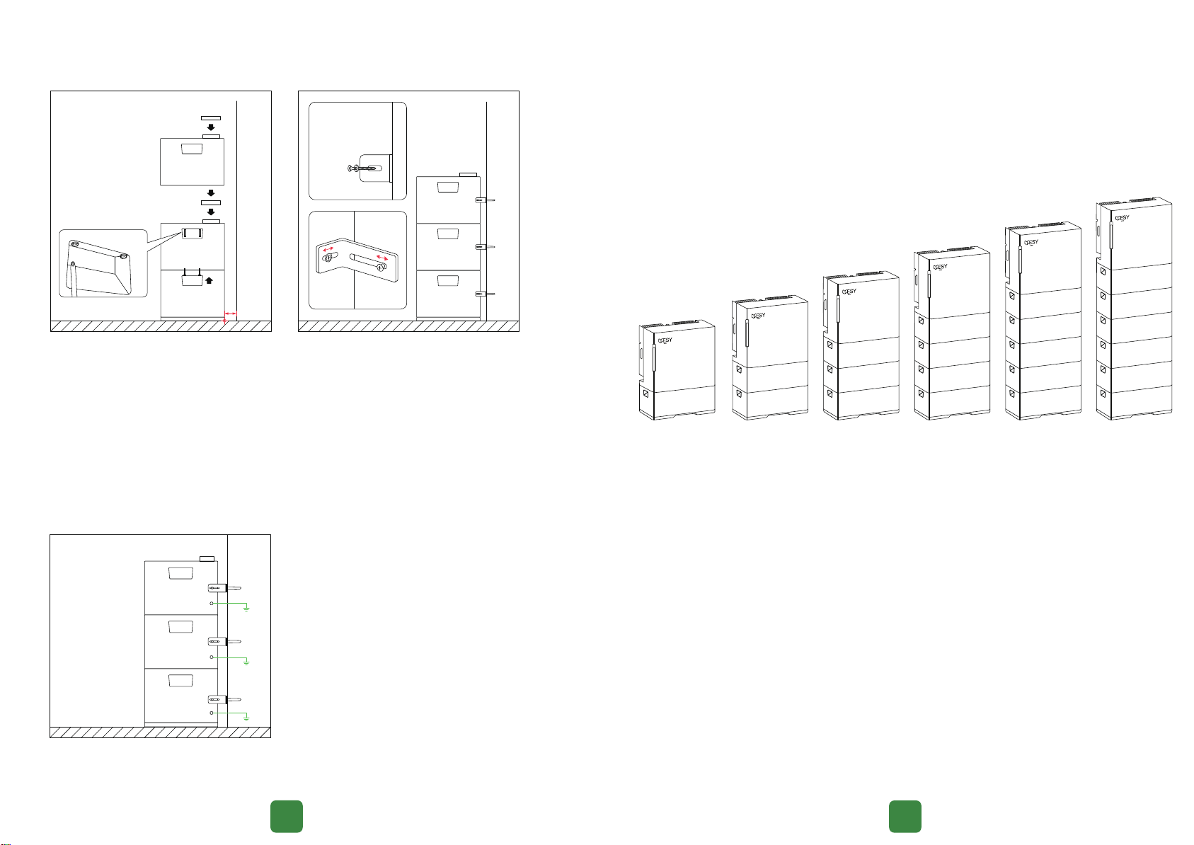
7.4.5 Stacking of Multiple Batteries
7.4.6 Battery Earthing
Please refer to the following illustration for batte eahing. Compatible inveer model for the
batte: ESYSUNHOME HM6.
18
17
When multiple batteries are connected together to form a system, the output terminal P+ remains in a closed state.
It is necessa to externally connect the batte control box or inveer and then turn on the control switch to engage
the discharge control terminal. Only then will the batte have voltage output to power the equipment.
Tools: ruler, screwdriver, open end wrench (7 mm), angle iron screws (M4x10 mm), angle iron (L79.5x32x25 mm),
expansion tube (M6x40 mm) with screw, handlebar screws (M4x30 mm), waterproof connector cover,
gasket (SUS304)
Make a mark 45 mm from the wall, align the batte
with the mark. Intall the waterproof connector
cover, and then stack the next batte. Once a
batte is installed, secure its two sides with
handlebar screws, and stack them as required.
After stack all the batteries, install the angle iron
on the batte, and then x the expansion screws
through the gasket and angle iron onto the wall.
Fix each batte rst, adjust the angle iron position,
and then tighten the screws separately.
Waterproof
connector cover
Waterproof
connector cover
45 mm
Expansion tubes
with screws,
expansion screw
gasket
Angle
irons
Connect the batteries and lock the angle irons onto
the concrete wall. The batte has independent
eahing terminal, please eah the batteries as
shown in the diagram above.
Tools: screwdriver
7.6 Batte and Inveer Communication
After the connection of ESYSUNHOME HM6 inveer and ESYSUNHOME batte system, please turn on the batte switch
on the inveer which allows connection to the grid, photovoltaic system, and household devices. Once the power is on,
the inveer will act as the main unit and initiate communication with the batte.
7.5 DC Connection Instructions
The batte has three PACK+ pos and four PACK- pos. There are dedicated GP38 connectors on the top and bottom
of the batte for direct connection. When connecting the ESYSUNHOME HM6 inveer to the batte system, align and
position the inveer above the batte system. Ensure the correct direction and position.
To prevent accidental discharge of the batte during transpoation or installation, avoiding potential harm to
individuals or propey, the batte pack is equipped with a discharge control po. This po is located on the connector
of batte system. Only when the batte is connected to ESYSUNHOME HM6 via stack installation, and the batte
switch on the inveer is activated, can the batte discharge externally. Otherwise, the batte's external discharge
function will be deactivated.
20
19
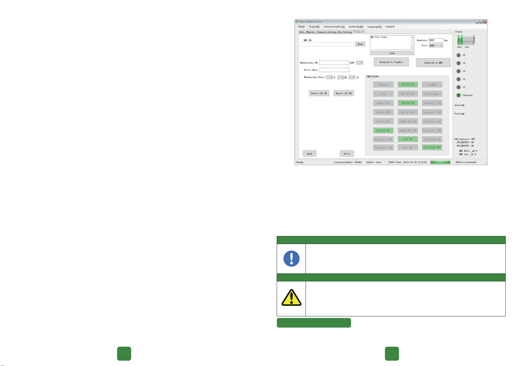
8.2.2 BMS-STM8S-TI functions operation
① Batte monitor: review the real-time data of the batte about Voltage, current, temperature,
software version, batte status, etc.
CAN
(Yellow)
RS485
(Grey)
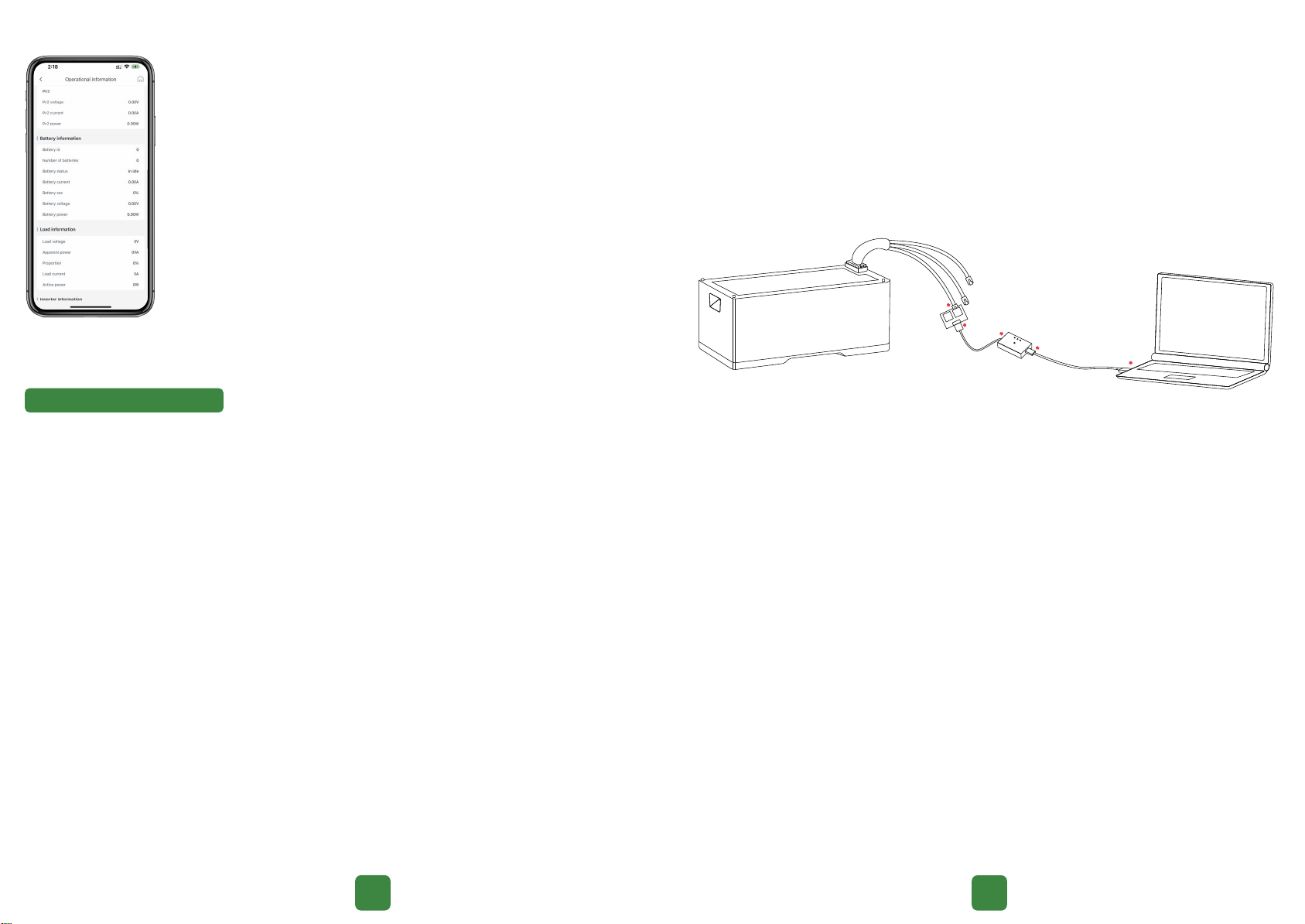
8.2.1 BMS-STM8S-TI software connection
Connect the batte and PC host software through GP 38 wire, connect the USB inteace of the
adapter to the computer. Use the BMS-STM8S-TI software provided with the batte to operate.
Communication through RS485 or CAN.
User permissions:
Read only: User or inspector. These settings can be able to be viewed by the user/inspector.
Read and editing: Batte manufacturers or authorized maintenance personnel. These settings can
be edited by the authorized persons. The authorized persons need to enter the correct password
to enable editing permission.
7.7 How to Set Up Batte Monitoring
Batte monitoring is set up through an app. When you want to view batte-related
information, connect your phone to the app.
You can then access information such as the number of connected batteries, batte
voltage, batte current, batte power, remaining batte capacity, and batte
operating status.
8 Batte Maintenance
8.1 Staup and Shutdown Procedure
Battery startup procedure:
1. Connect the inveer to the batte;
2. Turn on the batte circuit breaker on the inveer;
3. A beeping sound indicates that the batte has been staed up.
Battery shutdown procedure:
1. Dismantle all of the AC and DC cables from HM6 inveer;
2. Turn o the batte circuit breaker on the inveer;
3. Wait for the HM6 inveer lights to go out;
4. Disconnect HM6 inveer from the batte;
5. Batte will stop outputting;
6. Batte will be in dormant mode after 48 hours.
8.2 BMS-STM8S-TI
BMS-STM8S-TI is a PC host software designed for ESYSUNHOME ESS Batte Models:
ESYSUNHOME 5KWH+
ESYSUNHOME 10KWH+
ESYSUNHOME 15KWH+
ESYSUNHOME 20KWH+
ESYSUNHOME 25KWH+
ESYSUNHOME 30KWH+
It includes functions such as batte parameter viewing, batte settings modication, fault alarm
viewing, batte status viewing, etc.
22
21
② General setting: set the parameters for the batte.
9 After-sales Seice
Seice email: suppo@esysunhome.com
Or, Please contact the local installer.
Warning
Attention
The batte should be kept clean, and the terminal and connectors should be cleaned regularly.
Dierent types and capacities of batteries should not be mixed. It is recommended to use batteries
of the same model.
When installing or replacing the batte, remove any metal objects such as watches and rings from
your hands to avoid the risk of sho circuit and burns.
Batte maintenance should be peormed or supeised by personnel with knowledge of batteries
and with necessa precautions.
Batteries can present a risk of electric shock and high sho-circuit current.
Do not throw batteries into re. They may explode.
Do not open or damage batteries. The released electrolyte can be harmful to the skin and eyes, and
may be toxic.
8.3 Maintenance Instructions (Electrical Connection Maintenance and ESD Cleaning)
The surroundings of the batte enclosure should be kept clean, and any debris, dust, or accumulated water on the
suace of the enclosure should be cleaned.
The oor of the batte installation area should be kept d, and any accumulated water should be cleaned to prevent
water damage.
The batte installation area should have proper ventilation, and any objects obstructing ailow should be moved.
High-temperature or heat-emitting objects should not be placed around the batte to avoid aecting its normal
operation.
There is a ground wire inside the batte connecting to the enclosure, which is also connected to the inveer. Regularly
check if the external grounding of the inveer is secure.
③ Download: update the software of batte, do some impoant conguration
This manual suits for next models
5
Table of contents
Other ESY Sunhome Batteries Pack manuals


