ESY Sunhome HM6 User manual

ESY Sunhome Co., Ltd.
Made in China
HM6 Residential Energy Storage
System User Manual

ESY SUNHOME (“ESYSH”), a new energy storage
product company, was originally formed as a
protection systems and a highly professional R&D
team. These were essential technical foundations
as the founder looked to shore up his brand mission
that there were not many energy storage products
he was struck by the potential link between lithium
The team decided to take the plunge into the
quality control professionals with backgrounds of
Mission:
Vision:
Core Values:
Unity and hard work;
Contributing to society.

Table of Contents
1.3
1.2
1.1 General Statement 01
4.3 Ground Wire Connection 24
4.4 Load Connection 25
4.5 Power Grid Connection 27
4.6 Electricity Meter Connection 28
4.7 PV Connection 33
4.8 Communication Inteace 34
4.9 Power-on 36
Impoant Safety Information 02
2.1 Oveiew
2.1.1 Structural Features
04
2.2 Product Parameters 04
04
2.1.2 Functional Features 04
2.3 Appearance
2.3.1 Outline Dimensions
08
08
2.3.2 Pos 08
2.3.3 Nameplate Identication 11
2.4 Working Mode
2.4.1 Regular Mode
12
12
2.4.2 Electricity Selling Mode 12
2.4.3 Emergency Mode 13
2.4.4 AI Mode 13
2.2.1
Parameter of HM6 Inveer
Parameters of HM6 Residential
Energy Storage System
04
04
2.2.2
Parameters of 5KWH+ Residential
Energy Storage Batte
2.2.3
2.2.4 Module Models
07
07
Requirements for Installation and
Maintenance Personnel 01
4.2 Schematic Diagram of
System Connection 24
1 Precautions 01~02
2 Product Introduction 04~13
5ESYSUNHOME APP 36~39
3.1 Packing List
3.1.1 Packing List of HM6 Residential
Energy Storage System
14
14
4.8.1 WiFi-IOT Pro Communication
Inteace 34
3.1.2 Packing List of 5KWH+ Residential
Energy Storage Batte 15
3 System Installation 14~22
4.1 Instructions before Wiring
4.1.1 Cable Requirements
23
23
4.1.2 Precautions 23
4 Electrical Connection 23~36
6.1 Batte Status 41
6.2 Power Status 41
6.3 Alarm Status 41
6 Light Bar Indication 41
7 System Maintenance 42
7.1 Routine Maintenance 42
7.2 Precautions for Long-term Non-use 42
7.3 Batte Maintenance 42
8After-sales Seice 42
3.1.3 Base of 5KWH+ Residential Energy
Storage Batte 16
3.2 Preparation before Installation
3.2.1 Preparation of Installation Tools
16
16
3.2.2 Selection of Installation Environment 17
3.2.3 Selection of Installation Location 18
3.3 Installation
3.3.1 Location
19
19
3.3.2 Drilling 20
3.3.3 Bracket Installation 20
4.6.1 Electricity Meter Installation 28
4.6.2 Electricity Meter Conguration 29
5.1 ESYSUNHOME APP 36
5.1.1 Download Address 36
5.1.2 Registration and Installation 36
5.3 Data Monitoring 37
5.3.1 3D Scene Graph 37
5.3.2 Energy Flow Diagram 38
5.6 Remote Monitoring 40
5.6.1 Alarm Information Monitoring 40
5.6.2 OTA Upgrade 40
4.6.3 Use of Electricity Meter 31
5.2 Network Conguration 36
5.2.1 Install New Device 36
5.2.2 Add New Device 37
5.2.3 Device Network Conguration 37
5.4 Data Statistics 38
5.4.1 Real-time Power 38
5.4.2 Power Consumption Data 38
5.4.3 Revenue Data 39
4.8.2 Inteace Description 35
3.3.4 One Batte Installation 21
5.5 Power Supply Control
5.5.1 Mode Switch
39
39
5.5.2 Power Consumption Data 39
5.5.3 Cold Mode 40
5.5.4 Power-on/o 40
3.3.5 Stacking Multiple Batteries 22
3.3.6 Power Supply Installation 22

Esysunhome reserves the right not to assume any responsibility for consequences arising
from the following:
Noncompliance with the installation and use instructions outlined in this manual;
01
1. Precautions
1.1 General Statement
Statement
Statement
This manual applies to the HM6 residential energy storage system. Please read this manual
carefully and strictly adhere to all safety instructions during installation, operation, and
maintenance. Esysunhome will not be liable for any consequences arising from noncompliance
with the general safety requirements or safety standards of design, production and use.
It is crucial to use this product under the specied design conditions, as any damage to pas,
personal inju, or propey loss resulting from improper usage will not be covered by the warranty.
In addition, during installation, usage, and maintenance, all local laws and regulations must be
obseed. The safety instructions in this manual are supplementa to local laws and regulations.
personnel.
Safety facilities must be dismantled and inspected by professionals.
personnel.
1.2 Requirements for Installation and Maintenance Personnel
Professionals:
Trained personnel:
Operators:
professionals.

02 03
Danger signs
Danger!
Unauthorized removal, improper use or incorrect installation or operation may result in serious
personal inju or device damage. The transpoation, loading and unloading, installation, sta-up
and maintenance must be carried out by qualied or trained personnel.
Prior to attempting any repair, electrical installation, or accessing any live pas, make sure that the
power supply is cut o and wait for 5 min until internal capacitors are discharged to a safe voltage.
Do not connect the N wire of the load to that of the power grid, or connect the power grid cable to
the output end of the load. Doing so may result in serious damage to the product and load.
The external CT must be connected to the power supply properly and securely before use. Failure
to do so may result in high voltage at the CT pos
5min
Danger!
Danger!
Danger!
Warning signs
Installation must fully comply with national and local laws and regulations
Since the non-isolated topology is applied on the PV and grid side of the power supply, please use
monocstalline silicon or polysilicon batte panels (the negative PV must not be grounded).
When exposed to sunlight, the PV array will generate a high DC voltage. For installation safety, please
make sure that the entire PV panel is covered with an opaque cover before it is connected.
Warning!
Warning!
Warning!
Do not change the internal circuit of the power supply without permission.
Prior to power grid connection, the product must be securely grounded. Please follow the instructions
in this manual. Improper operation may cause serious losses.
Warning!
Warning!
Make sure that the input voltage of the inveer’s PV po never exceeds the maximum value. Exceeding
the maximum voltage may result in permanent damage to the power supply or other losses, [please
consider the inuence of temperature; and the voltage of the PV module is about 15% higher in winter
at -20℃compared to summer at 30℃ ]. Do not connect any energy source other than the PV module
at the PV input po.
Warning!
Please install a lightning protection device in the power distribution box.
Warning!
Install all terminals of the energy storage system in accordance with the instructions in this manual.
1.3 Important Safety Information

The ESYSUNHOME HM6 sma residential energy storage system is a 6KW energy storage type
power supply. The power supply is integrated with the batte and Internet or connected to the
power grid, PV panels and IoT, to supply power to homes, small supermarkets, farms, etc.
Emergency loads
Loads
Solar panels
Grid
Electricity Meter
Power generation data
monitoring platform
Wi/Bluetooth
04 05
2 Product Introduction
2.1 Overview
2.2 Product Parameters
2.2.1 Parameters of HM6 Residential Energy Storage System
2.2.2 Parameter of HM6 Inverter
Model
Rated power
Operating mode
ESYSUNHOME HM6
Monitoring software
Maximum input power
Maximum input voltage
Rated input voltage
Starting voltage
Minimum operating voltage
MPPT operating voltage range
(full-load voltage range)
Maximum input current
Maximum short-circuit current
Number of MPPTs
PV input
Number of phases
Rated input/output power
Maximum input/output apparent power
Rated voltage
Voltage range
Rated frequency
Frequency range
Rated current
Power factor
THDI (rated power)
Grid
Model
Standards
EMC Standards
HM6 residential energy storage system
The design of the power supply seamlessly combines both security and aesthetics, featuring a
The power supply uses natural heat dissipation to reduce the noise from air cooling. The noise
2.1.1 Structural Features
2.1.2 Functional Features
solar energy.
be stored and used for household needs.
power supply, which can be immediately turned on in case of power outages.
power grid, load, electricity price and weather, to ensure a stable power supply.
as well as the setting of operating modes, enabling users to monitor and control the system's
operation.
Rated power
Maximum output apparent power
Rated voltage
Rated current
Load

Grid charging
Rated voltage
Voltage Range
Charging current
Grid Charging
Maximum charging voltage
Maximum discharge current
Charging curve
Maximum efficiency
MPPT efficiency
Efficiency
06 07
Battery
2.2.4 Module Models
Module Model
Number of batteries
Maximum output power
Battery capacity (kWh)
Size (width × height × depth) (mm)
Weight (Kg)
5
6
6
Module Model
Number of batteries
Maximum output power
Battery capacity (kWh)
Size (width × height × depth) (mm)
Weight (Kg)
6
5
6
6
6
2.2.3 Parameters of 5KWH+ Residential Energy Storage Battery
Model
Battery type
Rated voltage
Voltage range
Rated capacity
Maximum charging current
Maximum discharge current
Rated power capacity
Operating temperature
Battery definition
Coding rule
EMC Standards
Waterproofing class
Protection class
Size (width × height × depth) (mm)
Gross weight (kg)
Net weight (kg)
Standards
ESYSUNHOME 5KWH+
Output voltage range
Output frequency
THDV
Overload capacity
Switching time
Load
Noise level at 1m
Size (width × height × depth) (mm)
Gross weight (kg)
Net weight (kg)
Altitude
protection
Others
Protection
Topology
Communication mode
Grid-connected standards
Standards
EMC Standards
Waterproofing level
Cooling mode
Installation
Relative humidity
Storage temperature
Operating temperature
AUS
DE
AUT
IT
UK
BE
CH
FR
ES
PT
Natural cooling
Installation on ground
)
08 09
Connection Diagram of 5KWH+ Residential Energy Storage Battery
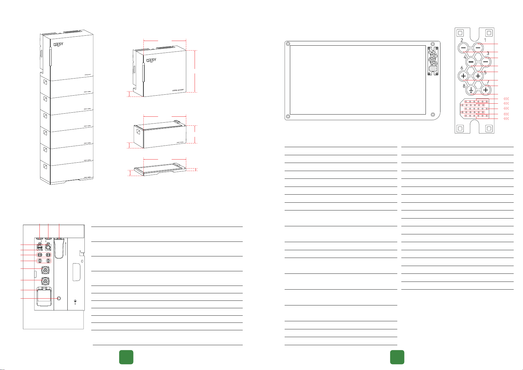
2.3.1 Outline Dimensions
2.3.2 Port Description
CT
USB
DRMS
01
02
03
04
05
06
07
08
09
11
10
Lateral marks on
the HM6 power supply chassis
Purpose of each lateral mark on
the HM6 power supply chassis
2.3 Appearance
01
02
03
04
05
06
07
08
09 14
15 20
21 26
27 32
33 38
Mark
NC
Signal cable for enabling
Signal cable for enabling
Mark
NC
NC
NC
NC
NC
NC
NC
Connection of external CT or
electricity meter signal
Upper computer connection to
control the product
Mark
product information
regulations
Exhaust of rapidly increasing gas
in chassis

Battery Connection Diagram of the HM6 Residential Energy Storage System
10 11
Pay attention to safety.
Pay attention to high suace temperature.
Be cautious of electric shock.
Prior to attempting any repair, electrical installation or accessing
any live pas, make sure that the power supply is cut o and wait
for 5 min until internal capacitors are discharged to a safe voltage.
Professional recycling is required.
Please read this manual before using the product.
Compliant with CE safety ceication standards.
2.3.2 Nameplate Identification
ESYSUNHOME: brand
HM6: model, indicating that the power supply specication is
6KW
ESYSUNHOME: brand
5KWH+: model, indicating that the batte specication is
5KWh
04
02
08
06
05
07
01
03
14 09
20 15
26 21
32 27
38 33
Mark
NC
NC
NC
NC
NC
Signal cable for enabling
Signal cable for enabling
Mark
NC
NC
NC
NC
NC
NC
NC
NC
NC
NC
NC
NC
NC
NC
NC
NC
NC
NC
NC

supply and any excess electricity is
sold to the power grid at maximum
output.
2.4 Working Modes
2.4.1 Normal Mode
2.4.2 Electricity Selling Mode
loads and household loads, followed
energy is then sold to the power grid.
in the battery are insufficient to meet
the load demands, power from the grid
will be used.
meet the load demands, the power
stored in the battery will be used as a
priority.
If energy is insufficient, batteries
will be charged from the power grid.
This is particularly suitable for charging
for an emergency.It is recommended
to use this mode when the electricity
price is low.
2.4.3 Emergency Mode
12 13
The system will intelligently select the
optimal mode depending on the user's
2.4.4 AI Mode
energy is insufficient, the
power stored in the battery will be
sold as asupplement to the power
grid.
energy is prioritized for charging
the batteries.
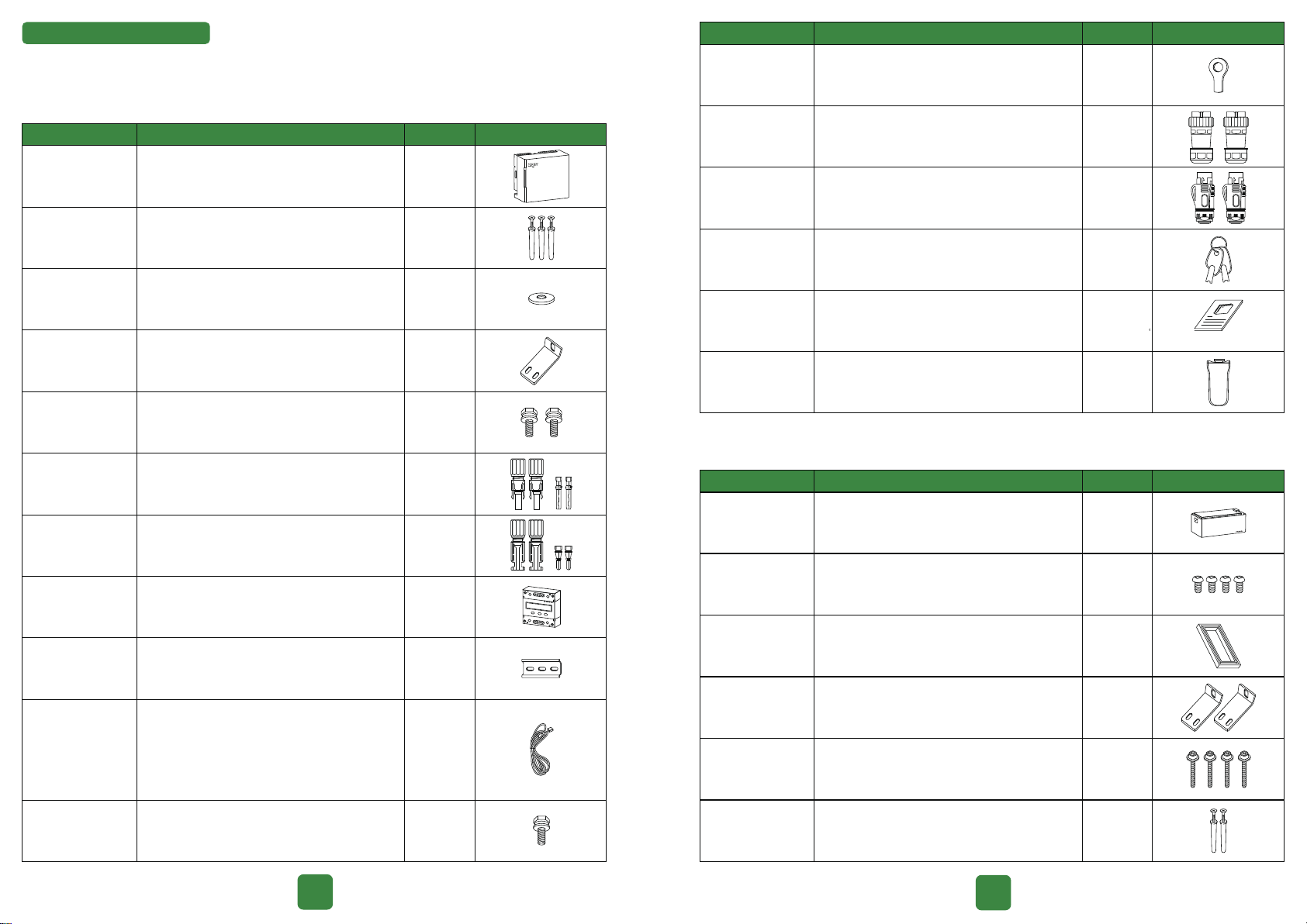
3.1.2 Packing List of 5KWH+ Residential Energy Storage Battery
14 15
3 System Installation
3.1 Packing List
Before installation, please carefully check the product and its accessories against the packing list.
Single bare copper wire, with one RJ45
crystal head and two pins (pin 4, pin 5) on
one end, and 40mm outer insulation and
5mm core insulation stripped, 3m long, for
connection between the HM6 residential
energy storage system and electricity meter.
Cross recessed outer hexagonal
double-gasket screw, M6*12mm
L60.5*32*25mm
1
3
1
1
2
2
2
1
1
1
1
Name Specifications Quantity Schematic Diagram
HM6 residential energy storage system
M6*40mm (guide rail *2, angle iron *1)
Inner diameter: 5mm;
outer diameter: 12mm;
SUS304 gasket
Cross recessed outer hexagonal
double-gasket screw, M4*12mm
VP-D4B-CHSM4 external terminal
casing, including metal terminal
VP-D4B-CHSF4 internal terminal casing,
including metal terminal
DDS3366D, English
RNB5.5-6,48A,
Φ=6.5mm,5.6×23mm
3-core waterproof male connector+crimped
10mm² cable LT28J3TP2
Waterproof protection plug of LAN port
communication cable (meter communication
cable *1, spare *1)
HM6, English
LSW-5A7153,5-12Vdc
Ring-shaped
crimp cable lug 1
2
2
1
1
1
Name Specifications Quantity Schematic Diagram
Residential
energy storage
system
Expansion tubes
with screws
Expansion
screw gasket
Angle iron
Angle iron
screws
PV+ connector
PV- connector
Smart electricity
Meter
Electricity meter
guide rail
Communication
cable
Ground wire
screw
AC output
terminal
LAN port
connector
Key
Manual
WiFi-IOT Pro
5KWH+ residential energy storage battery
PM4*8mm
Silicone, black, matte, 110*39.9* 9mm
L60.5*32*25mm
M4*30mm flange hex screws
6*40mm
Battery 1
4
1
2
4
2
Name Specifications Quantity Schematic Diagram
Fixing angle
iron screws
Waterproof
connector cover
Corner angle
irons
Handlebar
screws
Expansion tubes
with screws

Do not install it in a wet place or in water. Do not install it in areas prone to lightning strikes.
place.
For stability, the product should be installed on
perpendicular to the ground.
3.1.3 Base of 5KWH+ Residential Energy Storage Battery
3.2.1 Preparation of Installation Tools
3.2 Preparation before Installation
17
16
Installation
Type Tools and Descriptions
Electric drill
with M6 bit Spirit level Marker Ruler
Hammer
Screwdriver
Phillips
screwdriver
PH1
Allen
screwdriver
M2
Diagonal pliers
Utility knife Crimping pliers
Network cable
crimping pliers
Safety
Safety gloves Dust mask Goggles
Stripping pliers
Open-end wrench
S=7mm
3.2.2 Selection of the Installation Environment
It can be installed outdoors, but must not be
directly exposed to sunlight.
-25℃
≤90%
60℃
≤-25℃
≥90%
≥60℃
Inner diameter: 5mm; outer
diameter: 12mm; SUS304 gasket
Expansion
screw gaskets 2
Name Specifications Quantity Schematic Diagram
600mm*305mm*44.1mm
Silicone, black, matte,
110*39.9*9 mm (installed on the base)
PM4*8mm
Bracket
Waterproof
connector cover
Bracket
mounting
screws
1
1
4
Name Specifications Quantity Schematic Diagram

3.2.3 Selection of Installation Location
The clearances around the power supply must not be less than the following:
Top
800mm
Front
1000mm
Rear
40mm
Left
300mm
Right (door side)
600mm
Front
1000mm
Rear
40mm
Top
800mm
Left
300mm
Right (door side)
600mm
3.3 Installation
3.3.1 Location
1918
A
Measure the distance
Ensure the two holes are at the same height using the
A
B
holes.
A
B
C
Module Model
Number of batteries
Weight (Kg)
Size (width * height * thickness) mm
Module Model
Number of batteries
Weight (Kg)
Size (width * height * thickness) mm
5
6
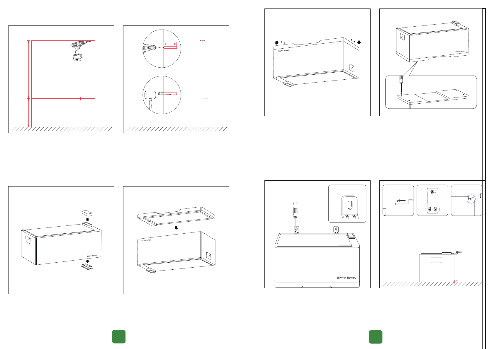
3.3.2 Drilling
Bit size
A
B
C
B
3.3.3 Bracket Installation
21
20
Once the installation location has been determined,
Bracket mounting screws
Handlebar screws
Hammer the expansion tubes into the holes.
Do not touch it.
3.3.4 One Battery Installation
secure them with the screws. Do not tighten the screws.
(including the bracket) with the mark. Install the expansion
screws through the gasket, and secure the angle irons
tighten them.
Expansion tubes
with screws,
expansion screw
gasket
Secure the screws only.
Do not tighten it.
Screws

(including the bracket) with the mark. Install the waterproof
secure the angle irons and expansion screws.
3.3.5 Stacking of Multiple Batteries
3.3.6 Power Supply Installation
on its right side, secure it with the screws.Do not tighten
the screws.
angleiron screws. Install the expansion screws through
the angle iron screws. Tighten the handlebar screws of
the and power supply using the .
power supply installation has been completed correctly.
tube with screw,
expansion screw gaskets
23
22
4.1 Instructions before Wiring
4.1.1 Cable Requirements
4.1.2 Precautions
as well as the ambient temperature, should be considered. The following table shows recommended
cables. Engineers should refer to local standards and the following table when selecting cables. The
table.
tools such as pliers. This can make system connections more secure and reliable.
Category
Grid/ AC Input (L﹐ N﹐ PE)
EPS/Load Output (L﹐ N﹐ PE)
PV1/PV2/PV Input (+﹐ -)
Cross-sectional Area of Conductor
4~6 mm²
4~6 mm²
4~6 mm²
Type of Circuit Breaker
400V.ac/40A
-
600V.dc/20A
Caution
Before installation and use, use a wire (4-6 mm²) with lug as the ground wire.
The capacity of the load output terminal of the power supply is as follows:
1. Inductive loads (e.g. air-conditioners, washing machines and motors): the individual
maximum power is 2.2 KVA, and the total maximum power is 6KVA.
2. Capacitive loads (e.g. computers and switching power supplies): the total maximum
power is 6KVA.
The above capacity is based on the system being connected to a power grid or batte
with sucient power. If the power is supplied solely by the PV module, the maximum
single o-grid load is usually half of the real-time power of the PV module.
Secure the screws only.
Do not tighten them.
screws
4 Electrical Connection
USB
DRMS
CT
open

25
24
ground wire
4.2 Schematic Diagram of System Connection
4.3 Ground Wire Connection
USB
DRMS
CT
Solar panels
Loads GND
Emergency loads
Grid
Smart electricity Meter
N
N
NATIONAL GRID
BIDIRECTIONAL
ENERGY METER
Measure the distance between the product and the power
distribution box using the tape, and select a ground wire
of appropriate length.
Be cautious
of
electric shock
pliers, install the ground wire terminal, and press it tightly
with crimping pliers.
4.4 Load Connection
Measure the distance between the product and the power
distribution box or load terminal using the tape, and select
a cable of the appropriate length.
Ensure the ground wire is properly connected to ensure
safety in installation and use.
wire screw
Fasten the ground wire terminal to the right radiator of the
ensure that the other end of the wire is properly grounded
USB
DRMS
CT
open
USB
DRMS
CT
Be cautious
of
electric shock
open

2726
Warning!
or touch the load’s output terminal and connecting cable.
Unscrew the output terminal. the white
waterproof seal and waterproof plug, and keep them
waterproof terminal using the
Install the wire cores through the waterproof plug and
cable terminal: N, and wires. Tighten the
screws of the waterproof terminal using the
Tighten the front end of the terminal
(with the waterproof seal in the correct position).
N
N
properly connected.
DRMS
USB
CT
open
4.5 Power Grid Connection
the distance to the power distribution box using the tape,
and select a cable of appropriate length. Secure the
Make sure that the power supply is properly grounded before operation. Do not connect
Install an circuit breaker between the power supply and the power grid before
connecting the power grid.
supply.
Caution
DRMS
USB
CT
open

2928
Measure the distance between the product and the
electricity meter using the tape, and select a network
cable of the appropriate length.
Strip the network cable using the stripping pliers and
install it through as shown in the
12345678
18
meter guide rail, slide rail screws, marker, hammer, electric drill, expansion screws, electricity meter
screws
4.6 Electricity Meter Connection
4.6.1 Electricity Meter Installation
Select the installation location of the electricity meter, and
make marks based on the screw holes of the electricity
meter guide rail.Drill holes using the electric drill, and install
expansion screws.
clamp the electricity meter on the guide rail.
Tighten the end of the terminal and ensure the cable is
connected securely.
terminal of the electricity meter (close the circuit breaker
of the power grid to power on the electricity meter and
are connected securely.
4
5
5
B C D
N
5
N
B C D
5
Connect the network cable with the waterproof terminal
DRMS
CT
CT
open

Low NO.6:LA 300002 Schematic Diagram
4.6.2 Electricity Meter Configuration
Steps
Ensure the parameters are set correctly.
” to change the digit. Set the
High NO.6 :HA 210510 Schematic Diagram
Baud Rate and Parity :09600
set
set
set
set
set
Schematic Diagram
Password 3366
Schematic Diagram
Schematic Diagram
3130
Caution
electricity meter and power supply is more than one month.
4.6.3 Use of Electricity Meter
set
set
Symbol Description
Total electricity, i.e. the sum of purchased electricity
and sold electricity
Ⅰ
Symbol Description
Ⅱ
“” and “
Schematic Diagram
Schematic Diagram
set
kWhⅠ
set
kWh
Ⅱ
Voltage ratio: PT 000001 Schematic Diagram
Baud Rate and Parity :09600
Schematic Diagram

33
32
4.7 PV Connection
Disconnect all circuit breakers of the power supply and
8mm to expose the copper wire. Install the copper wire
metal core of the connector and tighten it with crimping
pliers.
8mm
and metal terminal
and metal terminal
sound indicating a proper connection. Tighten the end
of the terminal. Ensure the cable and terminals are
connected securely.
input cable to the power supply. Ensure the cables are
connected properly.
DRMS
USB
CT
open
符号
set
Hz
Symbol Description
Energy SoldⅢ
c
Current
set
kWhⅢ
set
kW
set
V
set
A
set
Symbol Description
Symbol Description
Symbol Description
Symbol Description
Symbol Description
Schematic Diagram
Schematic Diagram
Schematic Diagram
Schematic Diagram
Schematic Diagram
Schematic Diagram
Hz Frequency
Other manuals for HM6
1
This manual suits for next models
3
Table of contents
Other ESY Sunhome Batteries Pack manuals

Popular Batteries Pack manuals by other brands

Impact Instrumentation
Impact Instrumentation 326M Series instruction manual

Nikon
Nikon MB-D16 user manual

Dragonfly Energy
Dragonfly Energy Battle born BB5024H User manual & installation guide

Panasonic
Panasonic CF-VZSU37U operating instructions

Mobee
Mobee Power Bar Quick install

LBS
LBS LBS-1275-SL Installation & user guide


