ET Hydrogen L/160 Troubleshooting guide

1

2
OPEN PACKAGE AND PLACE ALL ITEMS ON A WORKING BENCH TABLE.
The package contains: burner tips; user manual; quick start guide; DVD guide; USB tutorial guide; spare
fuse; plastic funnel; torch(es); fire proof plastic hose; power cord.
For a better understanding, Elettronica Todescato recommends to take vision of our DVD and/or USB Key
guide, and to simultaneously consult the present manual.
Step 1 Make sure that the switch is turn on “O” (OFF). Then, plug the power cord / cable into the
machine and into the electrical outlet make sure the voltage is make sure that the switch is
on the off position, “O”.
(3 POSITION SWITCH)
Step 2 PREPARE THE ELECTROLYTE SOLUTION
Carefully read Section 4.2 in the USER MANUAL and follow the instructions properly to
prepare the electrolyte solution. Make sure to understand the necessary pre-cautionary
procedures explained under the “DANGER“ symbol, in section 4.2 in the USER
MANUAL to avoid hazardous complications and mistakes.
NOTE: -2,6 liters of distilled or demineralized water needed to fill the tank.
-Mix with 1080 grams of KOH (Potassium Hydroxide).
-Let the chemical components cool down for 10 to 15 minutes or more.
-In appendix 1, there are Conversion Tables that can assist you in the amounts
needed for different units of measure.
ATTENTION!
Always use clean objects for
preparing the electrolyte solution.
If some of the tools used are not clean
wash it with tap water a few times
until it becomes clean and after
dry it with a rag.
DO NOT USE CLEANINGS
OR LIQUID SOAPS.
ATTENTION!
It is important to use protective
gloves and glasses
due to the corrosive
nature of the solution.

3
Step 3 UNSCREW THE SAFETY CAP ON TOP OF THE MACHINE.
( SAFETY CAP )
Step 4
Turn the switch into the down position ( “=” ) to refill, this will enable the operator to check
the level of demineralized water.
(3 POSITION SWITCH)
Notice:
a. Green light is “on”, indicating the machine is connected to the electricity (pic 1).
b. Yellow light is “on”, initially indicating the internal tank level is empty and needs to be
filled, or the water level is below normal during daily usage and there is need to add
more water. (see picture below).
c. Red light is, “off”, indicating that the internal tank needs to be filled.
4
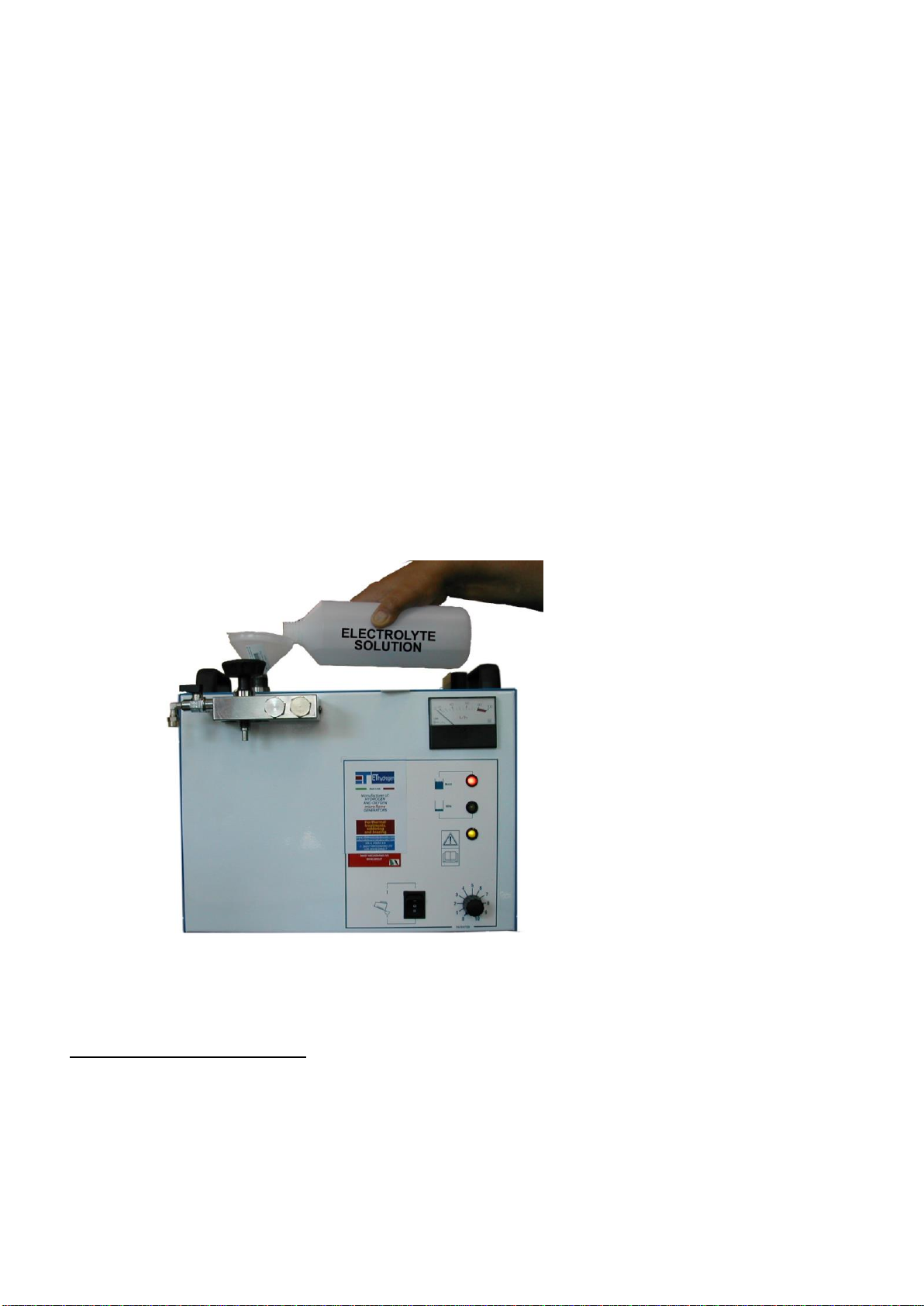
Step 5 POUR ELECTROLYTE SOLUTION
IMPORTANT NOTICE:
The electrolyte solution’s lifetime is of one year.
It must be poured when:
1- Using unit for the first time.
2- When solution has previously been poured through contaminated or dirty funnel.
3- When unnecessary or contaminated liquids have been poured inside the internal tank, such
as deoxidizer, etc.
After the electrolyte solution has cooled off, pour the solution into the internal tank (slowly) using a
funnel, until the Red-light indicator comes on, (pic. 2) indicating the internal tank is properly filled. At
the same time, the Yellow light will turn “off”, indicating that the tank is being filled and has reached
above the minimum level required. Stop pouring the solution, as soon as the red light comes on.
When the red light comes on, stop pouring the demineralized water, in order to avoid over filling the
tank.
(This is IMPORTANT: DO NOT OVERFILL). Then close the cap tightly safe.
Notice: The booster tank initially is disconnected.
Step 6 PREPARE THE DEOXIDIZER
FLUX (deoxidizer) Methyl Alcohol ( 1 liter ) + Boric Acid ( 15 –20 grams )
sec . 4.5 in the USER MANUAL),
contains the procedure and safety precautions to follow.

5
Step 7 BOOSTER TANK FILLING
Take the un-attached booster tank in hand, start pouring the deoxidizer in the booster tank by
placing your index on the hole in the center of the booster tank to avoid filing the interior chamber.
Fill to the maximum level indicated on the outside of the booster tank.
(DO NOT OVER-FILL)
EXAMPLE OF
HERMETIC SEAL

6
STEP 8.
BOOSTER TANK INSTALLATION
To mount the booster tank after having it filled with the flux (deoxidized), tighten the handle
knob making sure to not over screwing in order to preserve the gaskets and the internal
thread of the booster tank.
(BOOSTER TANK KNOB)
NOTE: For daily use and refill, refer to the section called “Attention “(page 14).
7
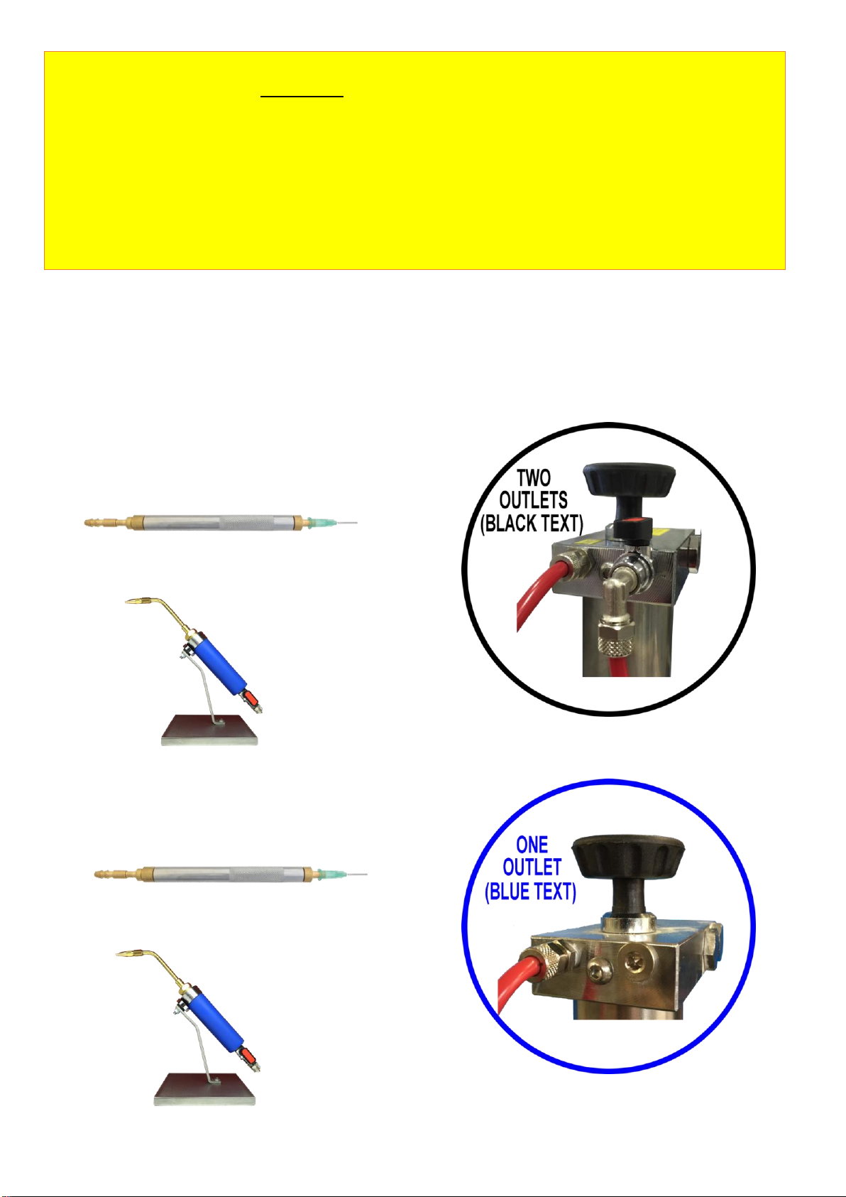
In the following steps, you must choose to operate with one or two outlets according to your
working needs.
Two outlets system is on the left side of the manual, starting from the next pages.
(highlighted in BLACK);
One outlet system is on the right side of the manual, starting from the next pages.
With the L/160 model, you can choose different working options:
SETTING THE MACHINE WITH TWO OUTLETS
YOU CAN WORK WITH:
•1, 2, 3 OR 4 STANDARD TORCHES.
•OR 1, 2, OR 3 SPECIAL TORCHES.
SETTING THE MACHINE WITH ONE OUTLET
YOU CAN WORK WITH:
•1 STARDARD TORCH (SUGGESTED).
•OR 1 SPECIAL TORCH (SUGGESTED).
! WARNING !
REMEMBER TO SHUT OFF ALL THE FLAMES BEFORE
DOING THE FOLLOWING OPERATIONS:
•OPENING THE TANK OR THE BOOSTER TANK FOR REFILLING OR POURING THE CHEMICALS.
•CHANGING OR ADDING MORE TORCHES, HOSES OR BURNER TIPS AND/OR NOZZLES.
•TURNING OFF THE MACHINE.
FAILURE TO FOLLOW THE UPPER ACTIONS WITHOUT SHUTTING OFF THE FLAME
MAY CAUSE THE BURNER TIP FUSING AND/OR BACKFLAME.

PROCEDURE FOR TWO
OUTLET SYSTEMS
Step 9.
With the model L/160 with two outlets, you
can use between one and four torches with
the following procedures:
NOTE: to connect the hoses properly, see
picture BELOW.
ONE TORCH:
Connect the hose to LINE 1 fitting (closest to
the machine), with the shut-off gas valve of
LINE 2 in the “off” position, then select the
green burner tip (refer to Table 2 –STEP 13)
and light the flame.
TWO TORCHES:
You must use the default LINE 1.
Connect the hose with the two split torches
to LINE 1 fitting (closest to the machine), with
the shut-off gas valve of LINE 2 in the “off”
position, then select the green burner tips
(refer to Table 2 –STEP 13) and light the
flames.
THREE TORCHES:
USE of LINE 1: Connect the hose with the
two split torches to LINE 1 fitting (closest to
the machine).
USE of LINE 2: Connect the hose with one
single hose and torch to LINE 2 by opening
the gas valve in the “on” position, then select
the green burner tips (refer to Table 2 –
STEP 13) and light the flames.
FOUR TORCHES:
USE of LINE 1: Connect the hose with the
two split torches to LINE 1 fitting (closest to
the machine).
USE of LINE 2: Connect the hose with the
two split torches to LINE 2 fitting by opening
the gas valve in the “on” position, then select
the green burner tips (refer to Table 2 –
STEP 13) and light the flames.
NOTE:
TO CONNECT THE HOSES TO THE
FITTINGS, UNSCREW THE FERRULE.
See Picture Below.
Then insert the plastic hose to the fitting,
tightening the ferrule to ensure a proper
and secure connection.
PROCEDURE FOR ONE
OUTLET SYSTEMS
Step 9 a.
NOTE: to connect the hoses properly, see picture
BELOW.
Prepare the special torch making sure the hose is
fitted (#16) to its fitting and the nozzle or burner tip
(refer to Table 2 or Table 2A) is selected and fitted
(#11).
SPECIAL TORCH
Step 9 b.
One Special Torch or Standard Torch (optional).
Connect the hose to the GAS OUTLET fitting, then
select the nozzle or burner tip (refer to Table2 or
Table 2A).
NOTE:
TO CONNECT HE HOSES TO THE FITTINGS, UNSCREW
THE FERRULE.
See Picture Below.
Then insert the plastic hose to the fitting, tightening
the ferrule to ensure a proper and secure connection.

TWO OUTLETS SYSTEM ONE OUTLET SYSTEM
9
STEP 10.
IMPORTANT: Before turning on the machine
set the power control knob to zero (see
picture below).
Step 11.
After mounting the booster tank, select the
green burner tip (0.8 mm).
Refer to TABLE 2, (Step 13).
WARNING: Failing to follow the values of
power regulation indicated in TABLE 2,
may cause the burner tip fuse and/or back
flame.
Step 12.
Turn “on” the machine by pushing the 3
position switch to the TOP position, where
the “-”is indicated. After a couple of minutes
this will start the gas emission.
(see picture below).
(3 POSITION SWITCH)
Step 10.
IMPORTANT: Before turning on the machine set the
power control knob to zero (see picture below).
Step 11.
After mounting the booster tank, select the burner tip
or nozzle (refer to table 2 or table 2A).
WARNING: When using burner tips, failing to follow
the values of power regulation indicated in TABLE 2 or
TABLE 2A, may cause the burner tip fuse and/or back
flame.
Step 12.
TURN ON THE MACHINE
Turn “on” the machine by pushing the 3 position switch
to the TOP position, where the “-”is indicated. After a
couple of minutes this will start the gas emission.
(see picture below).
(3 POSITION SWITCH)
TWO OUTLETS SYSTEM ONE OUTLET SYSTEM
10
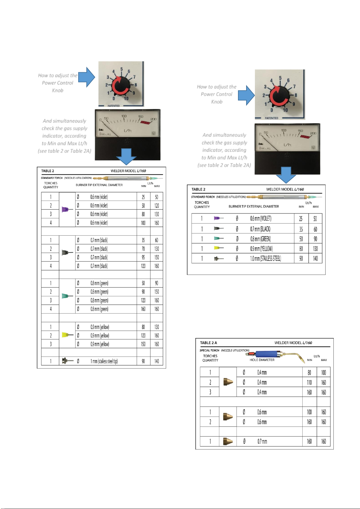
STEP 13.
HOW TO ADJUST THE POWER
ACCORDING TO BURNER TIP TIP SIZE.
STEP 13.
HOW TO ADJUST THE POWER
ACCORDING TO NEEDLE OR
NOZZLE TIP SIZE.
Adjust the power control knob using the gas supply
indicator according to the Min/Max values using
Table 2 or Table 2A.
NOTE:
Remember to not regulate the power under the
minimum value, indicated in Table 2. This may
cause the burner tip to fuse and burn excessively
or back flame.
How to adjust the
Power Control
Knob
And simultaneously
check the gas supply
indicator, according
to Min and Max Lt/h
(see table 2 or Table 2A)
How to adjust the
Power Control
Knob
And simultaneously
check the gas supply
indicator, according
to Min and Max Lt/h
(see table 2 or Table 2A)

TWO OUTLETS SYSTEM ONE OUTLET SYSTEM
11
Adjust the power control knob using the gas
supply indicator according to the Min/Max
values using Table 2 or Table 2A.
NOTE:
In order to insert the burner tip correctly, push
and rotate this item simultaneously at the
extremity of the torch, to make sure the burner
tip (picture A) is properly fitted. According to the
number of torches desired to use, and to the
diameter of the burner tip, remember not to
regulate the power under the minimum value,
indicated in Table 2. This may cause the burner
tip to fuse and burn excessively or back flame.
(picture A)
Adjust the power control knob using the gas
supply indicator according to the Min/Max
values using Table 2 or Table 2A.
NOTE:
In order to insert the burner tip correctly, push
and rotate this item simultaneously at the
extremity of the torch, so as to make sure the
burner tip (picture A) is properly fitted. According
to the number of the torches desired to use, and
with respect to the diameter of the burner tip,
remember not to regulate the power under the
minimum value, indicated in Table 2. This may
cause the burner tip to, fuse and burn
excessively.
(picture A)

TWO OUTLETS SYSTEM ONE OUTLET SYSTEM
12
Step 14.
Wait to the gas to exit from the burner tip
(approximately two/three minutes or more),
then light the flame with a lighter or
electronic igniter.
If the flame is too weak move on to the next
burner tip on table two (2).
(TORCH AND FLAME)
Step 15.
To turn off the machine switch the flame off
by pushing the base of the torch (as you do
with a pen), then ultimate the procedure by
turning the switch to “0”.
Always shut the flame OFF, before turning
machine off.
Do not turn the machine “off” while the flame
is lit.
Always, turn OFF the flame from the torch,
before shutting down the machine, always.
See picture below.
STEP 14.
NOTE 1 (REFERED FOR SPECIAL TORCH)
The operator will have to use the Gas Supply
Indicator –Power Control Knob/(Burner
Tip/Nozzle), with the min/max values, all
simultaneously in order to achieve the correct
flame desired, without burning the tips, before
lighting the flame. (See picture A,B,C).
NOTE 2 (REFERED FOR STANDARD TORCH)
After selecting the burner, screw the tip
(picture D) in place at the end of the torch, then
turn on the machine, while simultaneously using
the “Gas Supply Indicator” (picture C) for
gauging purposes. Then from Table 2/Table 2A
make sure the selected tip, does not go below
the Min/Max Lt/h value permitted, while also
using the Power Control Knob for adjusting
purposes. (Picture A).
Failure to follow the suggested Min/Max setting
will result in melted or fused burner tip/s.
(picture A)
(picture B)
(picture C)
(picture D)

TWO OUTLETS SYSTEM ONE OUTLET SYSTEM
13
Step 15.
Wait for the gas to be produced and exiting from
the torch, (approximately 2 or 3 minutes or
more) then light the flame with a lighter or
electronic igniter.
If the flame is unsatisfactory, move to the next
burner tip from Table 2/Table 2A.
(see picture below).
Step 16.
To turn the machine “OFF”, shut the flame off the torch
by pushing the torch hose fitting, if you use a standard
torch (picture 1), closing the shut off valve, if you use a
special torch (picture 2). Then push the (3-position
switch) to then central initial position, “O”.
Always shut the flame OFF, before turning machine off.
Do not turn the machine “off” while the flame is lit.
Always, turn “OFF” the flame from the torch, before
shutting down machine, always.
See picture below.
(PICTURE 1) (PICTURE 2)
HOW TO USE THE SPECIAL TORCH:
To turn on the flame, it is sufficient to open the
Valve at the base of the torch (“OPEN” position)
To turn OFF the flame, rotate the valve (quickly),
From “open” to “close” and then to “open” again.
(see step 16).
IMPORTANT NOTE:
IMPORTANT NOTICE:
The electrolyte solution’s lifetime is of one
year. It must be poured when:
1- Using unit for the first time.
2- When solution has previously
been poured through
contaminated or dirty funnel.
3- When unnecessary or
contaminated liquids have been
poured inside the internal tank,
such as deoxidizer, etc.
IMPORTANT NOTE:
For the first startup of our ET systems, or
for the yearly maintenance (once every
year), the machine must be filled or re-
filled with electrolyte solution.
For the daily re-fill it is mandatory to pour
only demineralized (or distilled) water
inside the electrolyte tank.
Pouring daily electrolyte solution will
cause a crystallization inside the tank and
consequent obstructions of machine’s
hoses, potentially causing a general
malfunction.

TWO OUTLETS SYSTEM ONE OUTLET SYSTEM
14
GOOD DAILY HABITS FOR
MAINTAINING THE MACHINE
AT OPTIMAL PERFORMANCE
A T T E N T I O N
1. Do not unscrew “booster tank” nor the
“safety cap”, while the flame is on.
2. Do not leave the machine on for more than
30 minutes, while the flame is “off”.
3. RE-Fill WATER IN THE INTERNAL TANK by
DEPRESSURIZING THE Booster Tank (first)
Whenever water or electrolyte solution needs
to be added to the (internal tank) it is
IMPORTANT to (Depressurize) the booster
tank (first) by simply unscrewing the handle-
knob (see photo in Step # 8). This will keep
the flux (deoxidizer) from contaminating the
electrolyte solution.
A) (unscrew safety cap) and add water or
electrolyte solution until the Red lamp comes
“on “, indicating its full.
B) afterwards re-tighten the safety cap and the
booster handle knob. Taking care not to over
tighten, or over-screw, or de-thread the
internal chamber. This will become a daily,
on-going standard operation, as water will
probably be constantly added to the (internal
tank), before starting the working day.
4. Do not turn the machine “off” while the flame
is lit. Always, turn off the flame from the
torch, before shutting down machine, always
do this as a pre-cautionary procedure.
5. Shut off the flame before refilling any liquid
flux (deoxidizer) or demineralized water) With
the tanks full, the machine will operate
approximately 6-8 hours.
6. If only the booster tank needs refilling, DO
NOT OPEN THE SAFETY CAP on top of the
machine. Just remove the booster tank and
fill accordingly to the max level position using
a finger in the center to avoid spilling fluid in
the improper location. Reattach the booster
tank when done filling.
GOOD DAILY HABITS FOR MAINTAINING
THE MACHINE
AT OPTIMAL PERFORMANCE
A T T E N T I O N
1. Do not unscrew “booster tank” nor the “safety
cap”, while the flame is on.
2. Do not leave the machine on for more than 30
minutes, while the flame is “off”.
3. RE-Fill WATER IN THE INTERNAL TANK by
DEPRESSURIZING THE Booster Tank (first)
Whenever water or electrolyte solution needs
to be added to the (internal tank)
it is IMPORTANT to (Depressurize) the booster
tank (first) by simply unscrewing
the handle-knob (see photo in Step # 8). This
will keep the flux (deoxidizer) from
contaminating the electrolyte solution. Then,
unscrew safety cap and add water or
electrolyte solution until the Red lamp comes
“on “, indicating its full. Then afterwards re-
tighten the safety cap and the booster handle
knob. Taking care not to over tighten, nor over-
screw, nor de-thread the internal chamber.
This will become a daily, on-going standard
operation, as water will probably be constantly
added to the
(internal tank), before starting the working
day.
4. Do not turn the machine “off” while the flame
is lit. Always, turn off the flame from the
torch, before shutting down machine, always
do this as a pre-cautionary procedure.
5. Shut off the flame before refilling any liquid
Flux (deoxidizer) or demineralized water
With the tanks full, the machine will operate
approximately 6-8 hours.
6. If only the booster tank needs refilling, DO NOT
OPEN THE SAFETY CAP on top of the machine.
Just remove the booster tank and fill
accordingly to the max level position using a
finger in the center to avoid spilling fluid in the
improper location. Reattach the booster tank
when done filling.

TWO OUTLETS SYSTEM ONE OUTLET SYSTEM
15
7. If both tanks need re-filling, first depressurize
the booster tank by removing it, then remove
the Safety Cap on top of the machine. Then
pour water in the Internal Tank until the Red
light comes on (indicting its filled). Re-insert
safety-cap back on top, then add the flux
(deoxidizer) to the booster tank and tighten.
8. Whenever the machine has been refilled, it
must be pressurized. Do not refill and let sit
over night without turning on to pressurize.
9. When pushing the (3-point switch) to the
down position, (fill-refill “= “), you will be able
to check the level of the demineralized water,
located in the internal tank.
a. If the Red light is off, then water is needed
in the internal tank, fill until the red light
comes, “on”.
b. If the yellow light indicator is “on”, then it’s
below the acceptable usage level and
water must be added.
c. If both the (Red & Yellow) lights are off,
then the water level is somewhere in
the middle of the tank.
10. If you use the machine once or twice a week,
every 15-20 days, turn –ON the welder
at least 3 minutes at max power without
lighting the flame, to avoid that the check
valve does not become blocked. After that,
turn, OFF the machine.
and DO NOT DEPRESSURIZE THE
INTERNAL TANK BY UNSCREWING THE
SAFETY CAP.
11. If two torches are selected, and during
operation, one of the two operators desires
to leave, shut off both torches; then
disconnect the hoses and then reconnect
one single torch. In this case the power
control knob must be readjusted for one
torch power.
If on the other hand, one of the two
operators chooses to stop using the torch
and turns the flame off, this can only be
done for 15-20 minutes since the gas will
be omitted into the environment. If the
period exceeds twenty minutes, just use
the default line nearest the machine with
one torch only.
7. If both tanks need re-filling first, depressurize the
booster tank by removing it, then remove the
Safety Cap on top of the machine.
Then pour water in the Internal Tank until the
Red light comes on (indicting its filled).
Re-insert safety-cap back on top, then add the
flux (deoxidizer) to the booster tank and tighten.
8. Whenever the machine has been refilled, it
must be pressurized. Do not refill and let sit
over night without turning on to pressurize.
9. When pushing the (3 point switch) to the down
position, (fill-refill “=”), you will be able to
check the level of the demineralized water,
located in the internal tank.
a. If the Red light is off, then water is needed in
the internal tank, fill until the
red light comes, “on”.
b. If the yellow light indicator is “on”, then it’s
below the acceptable usage level and water
must be added.
c. If both the (Red & Yellow) lights are off, then
the water level is somewhere in the middle
of the tank.
10. If you use the machine once or twice a week,
every 15-20 days, turn –ON the welder at least
3 minutes at max power without lighting the
flame, to avoid that the check valve does not
become blocked. After that, turn, OFF the
machine.
and DO NOT DEPRESSURIZE THE INTERNAL
TANK BY UNSCREWING THE SAFETY CAP.
11. If one (1) torch is selected for use, follow the
instructions at the beginning of the quick start
guide, (step 9). Essentially the L/160 will then
have one torch, and the operator will use the
machine accordingly.

TWO OUTLETS SYSTEM ONE OUTLET SYSTEM
16
12. Do not light the flame until the gas flows
out from the burner tip and at same time
the power control knob (MUST) be in the
correct position according to the Table 2
settings, before lighting the flame/s.
13. Clean the orifice (Fig. 1 # 11) with a thin
steal wire or other similar safe object, in
order to avoid causing personal harm or
damage to the burner tip. You can also
clean the burner tip in lukewarm water for
approximately twenty minutes.
12. If two torches are selected, and during
operation, one operator desires to shut off one
torch; then turn off the flame and then close
the valve. If, on the other hand, the operator
chooses to stop using the torch (nearest to the
machine) and turns the flame off, this can only
be done for 15-20 minutes since the gas will be
omitted into the environment.
14. Do not light the flame until the gas flows out
from the burner tip and at same time the
power control knob MUST be in the correct
position according to the settings in Table 2,
before lighting the flame/s.
15. Clean the orifice of the burner tip (fig.1 # 11)
with a thin steel wire daily before starting the
machine.

17
APPENDIX 1
INFORMATION ON CHEMICALS USED IN OUR HYDROGEN GENERATORS.
•ELECTROLYTE SOLUTION (LIQUID):
GO TO STEP 2 IN THE QUICK START GUIDE.
Electrolytic solution ready for use
COUNTRY
WELDER MODEL
QUANTITY OF ELECTROLYTE (LIQUID)
EU
L/160
EU LT 3
USA
L/160
US gal 0.792
UK
L/160
UK gal 0.659
•ELECTROLYTE SOLUTION IN DRY BAG:
GO TO STEP 2 IN THE QUICK START GUIDE.
How to prepare the electrolytic solution with dry bag.
COUNTRY
WELDER MODEL
QUANTITY OF
DEMINERALIZED
WATER
QUANTITY OF POTASSIUM
HYDROXIDE (KOH in FLAKES or
POWDER with 90% of PURITY)
EU
L/160
LT 2,6
grams 1080
USA
L/160
US gal 0.687
ounces 38.09
UK
L/160
UK gal 0.572
ounces 38.09
•FLUX (DEOXIDIZER) COMPOSITION:
GO TO SECTION 4.5 IN THE USER MANUAL.
The deoxidizer is a liquid with particular compounds(methyl alcohol + boric acid) in order to obtain
a clean flow solder. Useful for avoiding oxidation and porosity during the soldering / brazing
process.
The following table illustrate proportions and quantities to take in consideration in order to obtain
the correct deoxidizer and enable the machine function properly without obstructions.
FLUX (DEOXIDIZER) STANDARD COMPOSITION
(EU UNIT OF MEASURE)
1 Lt of Methyl Alcohol + (15 to 20) grams of Boric
Acid
FLUX (DEOXIDIZER) STANDARD COMPOSITION
(USA UNIT OF MEASURE)
US gal 0.264 of Methyl Alcohol + (0.529 to 0.705)
ounces of Boric Acid
FLUX (DEOXIDIZER) STANDARD COMPOSITION
(UK UNIT OF MEASURE)
UK gal 0.219 of Methyl Alcohol + (0.529 to 0.705)
ounces of Boric Acid
18
DANGER
! ATTENTION!
DO NOT TURN/UNSCREW THE
SAFETY CAP AND/OR THE HANDLE
WHILE THE FLAME/FLAMES ARE LIT
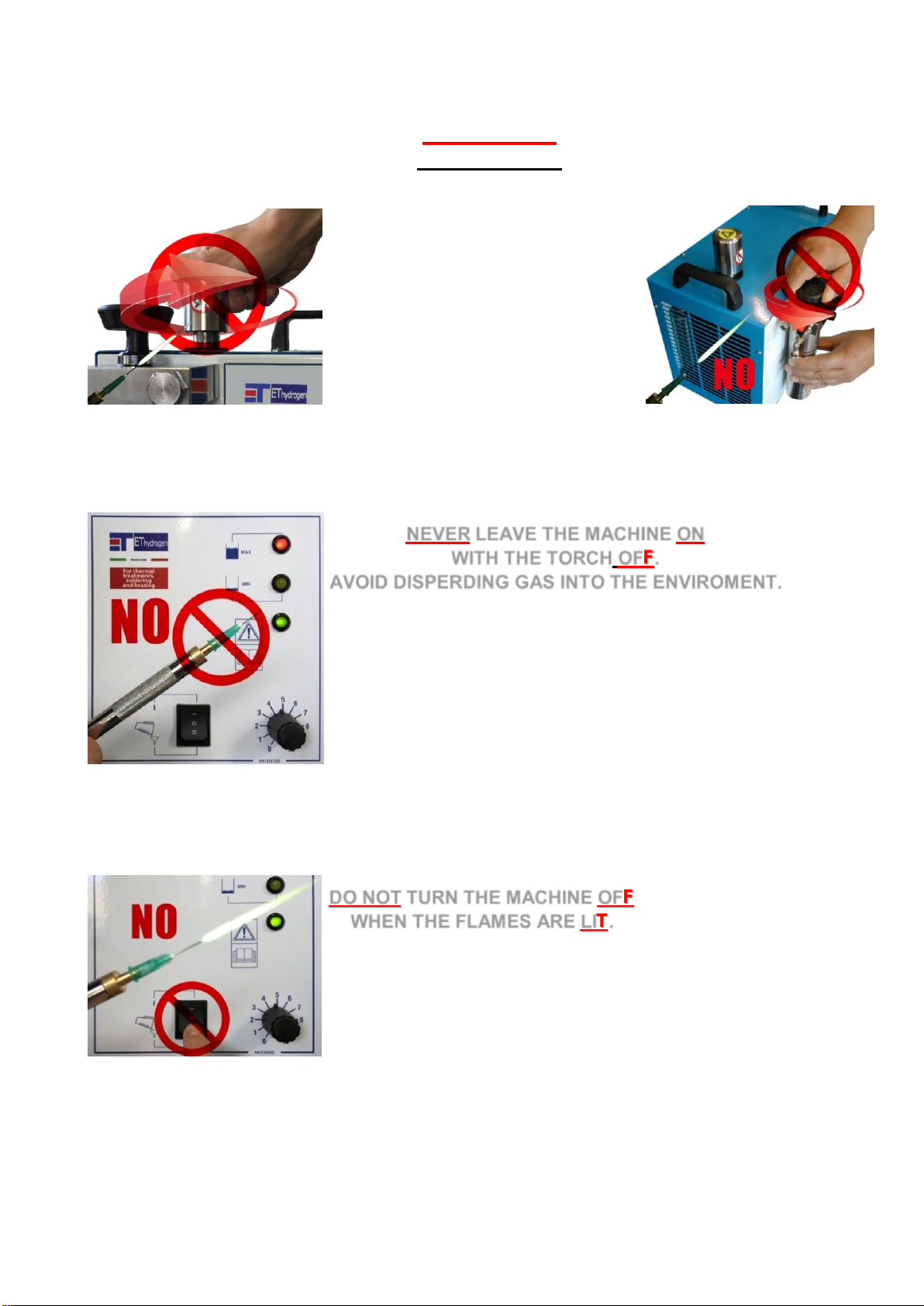
NEVER LEAVE THE MACHINE ON
WITH THE TORCH OFF.
AVOID DISPERDING GAS INTO THE ENVIROMENT.
DO NOT TURN THE MACHINE OFF
WHEN THE FLAMES ARE LIT.

19
DO NOT PLACE THE FLAME NEAR THE MACHINE,
IN PARTICULAR, ON THE BOOSTER TANK,
SAFETY CAP, THE FILLING NECK,
THE BOOSTER HANDLE KNOB
OR THE GAS HOSES.
DO NOT CUT THE GAS HOSES WHILE FLAMES ARE LIT.
NEVER LIGHT THE FLAME IF
BOOSTER TANK IS EMPTY.
NEVER LIGHT THE FLAME WHEN
THERE ARE NO BURNER TIPS OR
NOZZLES MOUNTED
ON THE TORCH.

20
ATTENTION: the flame reaches a very high temperature of (3200°C / 6100°F).
DO NOT COME IN CONTACT WITHIN THE VICINITY OF THE FLAME,
(WITH A MINIMUM OF 50 CM / 20 INCHES). THE FLAME IS VERY
DANGEROUS, AND MAY CAUSE, SEVERE ENJURIES IF THE OPERATOR
DOES NOT FOLLOW THESE RULES.
KEEP THE MACHINE AND ITS ATTACHED AND UNATTACHED
ACCESSORIES AWAY FROM CHILDREN.
Do not allow gas to enter the environment for more than 15-20
minutes.
Alternatively, it is best to turn off the machine completely.
ATTENTION!
ONCE A YEAR
For optimal performance of equipment, a yearly maintenance is
required, with instruction located in sec. 5.3 of the technical
user manual.
Table of contents
Other ET Hydrogen Welding System manuals


