ET Hydrogen L/350 Instructions for use

1
2

3
INDEX
1.1 Presentation
4
1.2 Warranty
5
1.2.1 Exclusions from warranty
5
1.3 Machine identification
5
1.4
Equipment 7
1.5 Machine description and use limitation
7
1.5.1 Description
7
1.5.2 Use limitation
7
1.6 Noise 7
1.7 Technical
features
8
SECTION
2:
Safety
and
prevention
2.1 Safety 8
2.1.1 General safety
regulations
9
2.2 Safety signs (Symbols)
10
2.3 Safe use and maintenance 11
SECTION
3:
Transport
and
installation
3.1 Packaging
12
3.2 Shipping 12
3.3 Unpackaging
12
3.4 Positioning
1
2
3.5 Storing 12
SECTION
4: Use
4.1 Connection to the electric
circuit
13
4.2 Preparing the
electrolyte
13
4.3 Tank
filling
14
4.4 Booster
filling
14
4.5 Preparing deoxidizer liquid
14
4.6 Hazardous operations
14
4.
7
Starting the machine
15
4.8 Stopping the machine
15
4.9 Backfire
16
4.1O
Safety devices
17
4.11 Refilling deoxidizer liquid
18
4.12 Refilling distilled or demineralized water
18
SECTION 5: Maintenance
5.1 Generalities
17
5.2 Every six months
17
5.3 Once year
18
5.4 Every four year
18
5.5 Putting the machine out of service
18
5.6 Scrapping
18
5.7 Disposing of the
electrolyte
18
5.8 Disposing of the liquid
deoxidizer 18
5.9 Trouble shooting
19
5.1
O
Interventions
21
5.10.1 What to do in order to see if the tank
is
short-circuited
21
5.10.2 Controlling pressure, adjustment valve
21
5.10.3 Checking valve tightness 22
5.10.4 Replacing the valve
22
5.10.5 Replacing the
electrolyte
23
SECTION
6:
Spare
parts
6.1 Spare parts
23
FIGURELIST
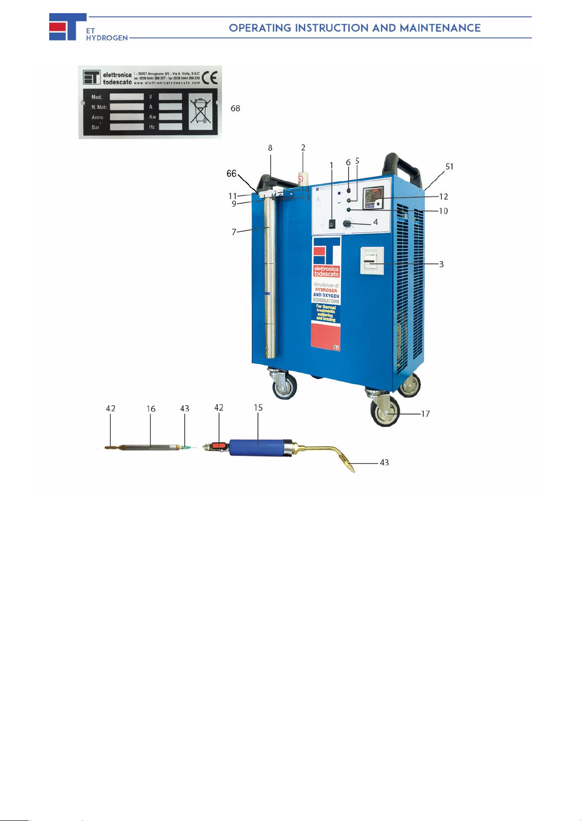
Fig.1 Welding and components
6
Fig.2
Machine Layout
8
Fig.3 Safety signs
10
Fig.4 Valve replacement
22
Fig.5 Spare parts
24
Fig.6 Wiring diagram 27
Tab.6 Special torch 30
4
SECTION 1
Description and main features of the welder
1.1 PRESENTATION
This manual gives information regarded as necessary to know, use correctly and carry out normal
maintenance operations on this welder « L/45 » (hereinafter referred to as machine) fabricated by
«Elettronica Todescato S.r.l.» di Arcugnano (Vicenza) Italy (hereinafter referred to as Manufacturer).
The material in this manual is not intended to be a complete description of the parts nor a detailed
explanation of their option. The user, however, will find the kind of information normally required to
operate the machine correctly and safely and also to keep in good working condition.
Compliance with and observance of what is described in the manual is an essential condition for the
trouble-free operation, long life and cost effective performance of the machine.
ATTENTION
Failure to observe the instructions in this manual, negligence, incorrect or improper use of the
machine can be cause of machine warranty coverage cancellation by manufacturer.
Manufacturer therefore declines any and all liability for injury to people or damage to property
caused by failure to follow the instructions given in this manual.
Service work or overhauls involving complex operations must be entrusted to an authorized Technical
Service Center which has the necessary specialized personnel, or directly to the Manufacturer who is at
your complete disposal to ensure fast and complete technical assistance and anything else that can
promote improved operation and optimal performance by the machine.
DANGER
This manual must be kept in a safe place at the disposal of the operator and service engineer,
for consultation at any time during the machine’s entire working life. It should be delivered with
the machine if the latter is sold.
The manual must be kept in a safe place that is familiar to the assigned personnel. It is the
responsibility of the personnel to keep the manual complete to allow for a consultation for the
entire life of the machine. If the manual is damaged or lost, a copy must be immediately
requested to the Manufacturer.

5
1.2WARRANTY
Elettronica Todescato Srl ensures that the machine referred to in this manual has been tested in its own
premises. The machine is guaranteed for 1 year (12 months) from the date of purchase. Should the machine
be tampered with or improperly used, particularly concerning the safety devices, the warranty will be voided
and the manufacturer will be discharged from any liability whatsoever. Upon delivery, make sure that the
machine has not suffered damage during transportation and that it is complete with all standard accessories
and any optional equipment specifically ordered. Complaints must be written and submitted to your reseller
within and not later than 8 (eight) days.
1.2.1 EXCLUSIONS FROM WARRANTY
This warranty shall be null and void (apart from the causes given in the Purchase Contract):
- If the machine is used with incorrect voltage.
- If the damage is due to insufficient maintenance or lack of proper service.
- If, following repairs carried out by the owner without manufacturers consent due to installation of non-
original spare parts, the machine has been changed and the damage was caused by these changes.
- If the instructions given in this manual were not followed correctly.
- Exceptional events.
Damage caused by negligence, lack of care, improper and bad use of the machine or incorrect maneuvering
by the operator shall also cause this warranty coverage to be null and void.
ATTENTION
Removal of safety devices installed on the machine will automatically make this warranty null and
void of the Manufacturer.
1.3 MACHINE IDENTIFICATION
Each machine is equipped of identification plate (fig.1 # 21), giving the following information:
- Name and address of Manufacturer;
- «CE» mark;
- A) Machine type;
- B) Year of fabrication;
- C) Serial number;
- D) Voltage;
- E) Ampere;
- F) Watt;
- G) Frequency;
- H) Pressure.
The data given on the identification plate should be written in the spaces provided on the back cover
of this manual and should always be specified when ordering spare parts or requesting Technical
Assistance.
6
...
-
.
FIG.
1 -
WELDING AND
COMPONENTS
LEGEND
Fig.1
1.
Three-position
switch
2. Safety cap
3.
Circuit
breaker
4.
Power control
knob
5.
Minimum
level indicator light
(yellow)
6.
Maximum level indicator light
(red)
7. Booster
8. Handle knob
9. holder
10. On
indicator l
ight
11.
Shut-off
valve-
12.
Gas supply indicator
1/hour
13. Flame arrester cap
14.
Check valve
cap
15.
Specialtorch
(brass nozzle
type)
16.
Standard torch
(needle
type)
17. Wheel
42. Torchhose fitting
&
shut-offvalve
43. Burner
tip
51. Power
cord
230
V.50
Hz.
56. Torch hose
66. Torch hose fitting
68. Identification plate & her position

7
1.4 EQUIPMENT
Standard Eq
uipment:
−
Burnertip
−Sparefuse.
−power cord
−fire proof rubber hose
−plastic funnel
−
User Manual
Optionals:
−Can containing liquid deoxidizer.
−Can containing
−
Torch
holder
−
2.5 Bar pressure gauge.
−One Year Maintenance Kit
−MACHINE DESCRIPTION AND USE LIMITATION
The
«ET- hydroge
n L/350 Welder
is a
machine marked
with « CE» symbol in compliance
with European
Union
regulation
s
pursuant to
EEC Directive
2014/35/UE and 2014/30/CE
as
detailed in the UE
Declaration
of
Conformity annexed to
each
machine.
DESCRIPTION
The «ET Hydrogen Welder L/350» can be used in craftwork or industrial workshop with a
minimum volume of 30 m³ and provided with natural ventilation by means of suitable openings to
the outside in compliance with the regulations in force in the user’s country. This machine is mainly
used for soft and hard brazing applications in the fields of jewellery, goldsmith, costume jewellery,
dental mechanics, micromechanics, and for welding materials such as platinum, beryl, nickel,
thermocouples, enamel copper, glass, quartz and for welding metal to metal and applicable for
welding in industry, within the limitations of the machine.
USE LIMITATIONS
The hydrogen and oxygen mixture produced by this welder must be solely used to produce one
flame for braze welding or thermal treatments of metal parts in general, or for working quartz glass.
DANGER
Any use different from those quoted here within and not included or not directly inferred
from this instructions’ manual, will be regarded as «NOT ALLOWED».

8
It is not permitted to operate the machine when the flame is out. This would result in an
accumulation of explosive mixture in the surrounding environment and pollution caused by
the methyl alcohol.
The machine has been designed for professional use. The operator must be of proven
ability and capable of reading and understanding the instructions given in this manual.
The operator must also use the machine in accordance with the ruling accident prevention
standards, operating conditions and characteristics of the machine.
DANGER
THE USE OF THE MACHINE FOR ANY OTHER PURPOSE THAN THAT DESCRIBED IN THIS
MANUAL RELIEVES THE MANUFACTURER OF ANY RESPOSIBILITY FOR DAMAGES TO
PERSONS, ANIMALS OR THINGS RESULTING FROM INAPPROPRIATE USE.
1.6 NOISE
The noise level (acoustic pressure) was determined with the machine running under no load
conditions with the readings of the 70 dB(A) inferior.
1.7 TECHNICAL FEATURES
/
9
FIG. -MACHINELAYOUT
H2/O2Gas production
It/h
350
Water consumption
gr/h
175
Alcohol consumption
gr/h
57
Booster tank capacity
Lt
0,68
Maximum power
Watt
1500
Electrolyte
Lt
6,6
Weight
Kg
95
TABLE 1
SECTION 2
Safety and Prevention
2.1 SAFETY
The owner of the machine must instruct personnel about the risk of industrial accident, the safety
device installed for operator safety and on general industrial accident prevention regulations applied
by law in the country where the machine is to be operated.
Operator safety is a matter of considerable importance for machine design and fabrication. When
designing a new machine, every effort is made to foresee every possible dangerous situation and,
naturally, adopt suitable safety devices to counter them. Therefore, a careful reading of this manual
and special care and attention whenever any intrinsically operations have to be carried out are
obligatory.
DANGER
Manufacturer declines any and all liability for injury to people or damage to things caused by failure
to follow this safety regulation and accident prevention recommendations detailed here.
Pay further attention when you see this symbol in the manual.
2.1.1 GENERAL SAFETY REGULATIONS
10
ATTENTION
Failing to comply with the information described in «Section 2 –Safety and Prevention» and
the mishandling of the safety devices relieves the Manufacturer from any responsibility in
the event of accidents, damage or machine malfunctions.
General rules:
- The user undertakes to entrust the machine to qualified and trained personnel only.
- The user is bound to take all the necessary measures for preventing unauthorized
personnel from accessing the machine.
- The user undertakes to provide its personnel with adequate information regarding the
application and observance of the safety regulations. To this end, the user undertakes to
ensure that all the personnel understand the machine operating instructions and the safety
regulations relative to their particular responsibility.
- The user must inform the Manufacturer of any defects or malfunctions in the accident
prevention system and any situations of potential danger.
- The personnel must use the personal protection items provided for by law and respect
instructions given in this manual.
- The personnel must respect the danger and caution symbols on the machine.
- The personnel must not perform operations or interventions under their own initiative that lie
outside their competence.
- The personnel is obliged to notify superiors of any problem or dangerous situation that may
arise.
- The machine has been commissioned and tested with all the parts included within the
standard equipment. The installation of parts or other makes or modifications to the machine
may vary its characteristics and compromise its operating safety.
- The machine must only be used for the purpose for which it was constructed.
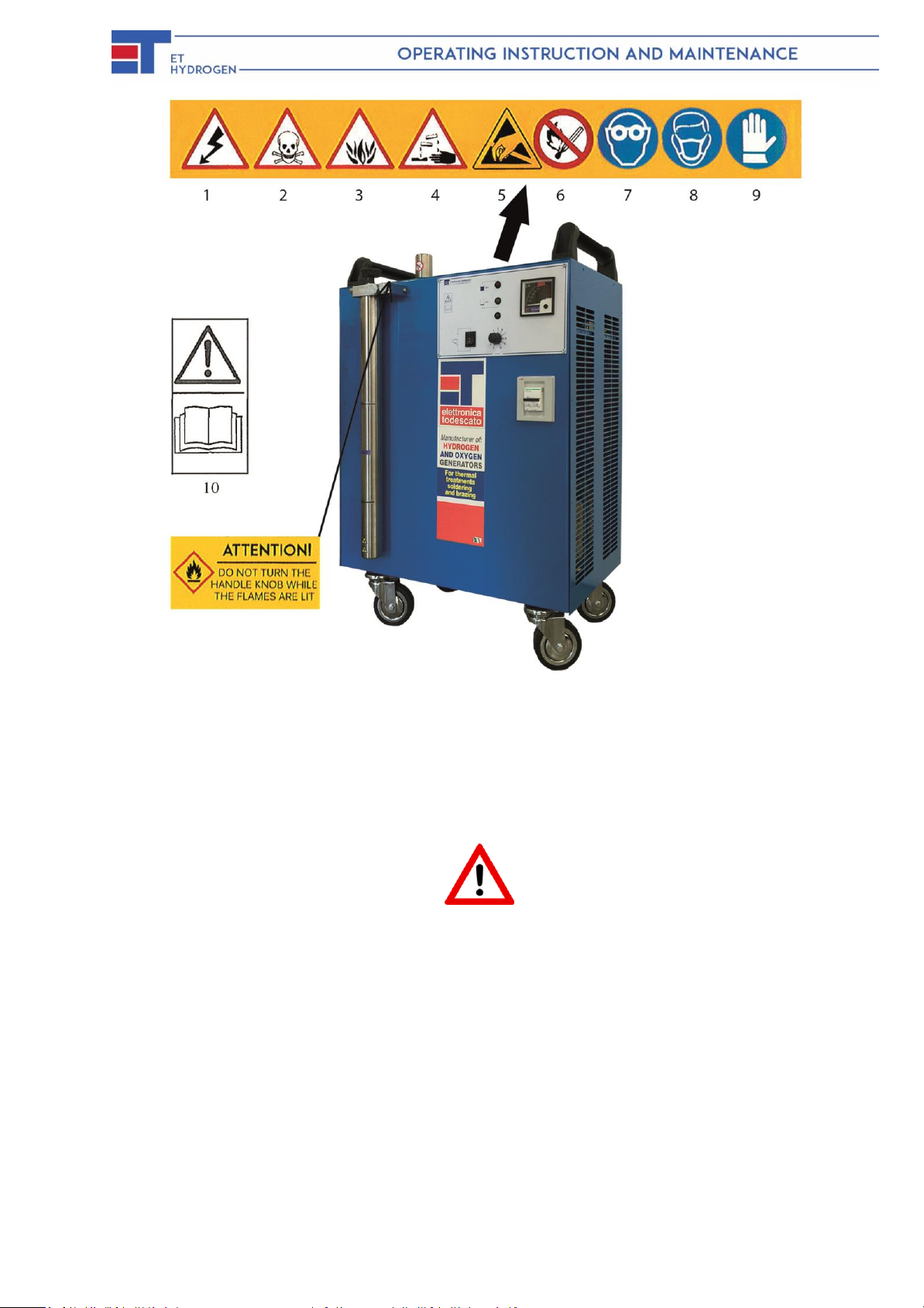
2.2 SAFETY SIGNS (Symbols)
During the construction of machine, all the possible solutions for the safety the operator have been
adopted. The machine may nevertheless present ulterior risks which have not been possible to
eliminate completely under certain operating conditions. These risks have been highlighted on the
machine with adhesive warning symbols that indicate the various situations of reduced safety or
danger.
ATTENTION
Keep the safety stickers clean and replace them immediately if they are peeling away or are
damaged.

11
The following warnings refer to Figure 3. Read them carefully and learn their meaning.
1) Excessive voltage. Before interventions, disconnect power.
2) Toxic substance, if swallowed. Do not inhale the vapors.
3) Easily flammable.
4) Corrosive liquid when in touch with body members.
5) Attention, electrostatic discharge sensitive device.
6) Flammable. Do not approach free flames.
7) Use protection glass.
8) Use protection mask for respiratory tract.
9) Use protection gloves.
10) Before using the machine, read the operating instructions carefully.
11) Attention, do not turn the handle knob while the flames are lit.
12
FIG. 3
·
S
·
AFETY SIGNS
2.3 SAFE USE AND MAINTENACE
ATTENTION
- The use of the machine is prohibited to:
oOperators who have not read and understood the instructions given in this manual;
oInexperienced persons;
oOperators not in good physical/mental health.
- Periodically check that the machine and its protection devices are in perfect working order.
- Before maintenance operations or repairs on the machine, disconnect power.
- Maintenance operations and repairs must only be carried out by personnel trained to
perform these special functions.
- At the end of the maintenance operations and repairs, before restarting the machine, the
technical foreman must check that the work has been finished, the safety device
reactivated and the protections reassembled.
- The spare parts must correspond with those stipulated by the Manufacturer. Only use
original spare parts.

13
- During maintenance operations and repairs, protective clothing must be worn, i.e.
protective eyewear, gloves for preventing cuts and mask for respiratory tract protection.
- Do not use water jets to clean the machine.
SECTION 3
Transport and Installation
3.1 PACKAGING
The welder is wrapped up in a polythene film and subsequently packed in a three-layer waterproof
cardboard box sealed with adhesive tape and secured by a double strap.
3.2 SHIPPING
Whatever transportation method is used, (either by plane, sea or land) continental or
intercontinental, the machine tanks will be empty.
If REQUESTED or where PERMITTED:
The packaged electrolyte salts and/or bottled demineralized water, will be shipped according to
the rules, law and regulations of the machine’s destination (country).
3.3 UNPACKAGING
Make sure that:
- The welder has not suffered damage during transportation and, if necessary, report to the
manufacturer or authorized reseller.
3.4 POSITIONING
Set the welder on a solid and stable surface, away from heat sources. Allow at least 50 cm of free
space for the cooling louvres on the machine sides, for proper air circulation.
3.5 STORING
When the welder is in storage, the tank must be filled with electrolyte (Fig.5 # 46) and the machine
must be started for a few minutes at least once a month.
Avoid storing in humid places.

14
SECTION 4
Use
4.1 CONNECTION TO THE ELECTRIC CIRCUIT
Check that the main voltage corresponds to the voltage indicated on the plate at the rear of the
welder (Fig. 1 # 21). Test the electrical circuit grounding to make sure that is it efficient.
- Slide the switch (Fig.1 # 1) to the “O” position.
- Insert power cable plug (Fig.5 # 31) into the current outlet.
4.2 PREPARING THE ELECTROLYTE
Pour 180 grams of KOH (Potassium Hydroxide) into a clean stainless-steel vessel and/or hard
plastic container that has been previously filled with 0,445 liters (0.118 US gal) of distilled or
demineralized water. If the vessel needs to be cleaned, wash it with tap water a few times, until it
becomes clean and after that, dry it with a rag. Stir immediately but gently, using a clean stainless-
steel implement, until the product is fully dissolved, producing a reaction that generates heat. Wait
until the solution has cooled down. DO NOT USE DETERGENTS OR LIQUID SOAPS.
DO NOT PREPARE the electrolyte solution inside the machine tank. It must be prepared into an
external vessel BEFORE being introduced inside the machine tank.
DANGER
AVOID SPILLS. ALLOW COOLING TIME.
THE ELECTROLYTE IS HIGHLY CAUSTIC AND CAN CAUSE SERIOUS SCALDS TO THE
SKIN AND HUMAN BODY. WHEN HANDLING THIS PRODUCT, ALWAYS MAKE SURE THAT
A CONTAINER FULL OF WATER AND VINEGAR IS WHITHIN REACH, IN ORDER TO BE
ABLE TO WASH IMMEDIATELY ANY PART THAT COMES INTO CONTACT WITH THE
PRODUCT AND SUBSEQUENTLY RINSE CAREFULLY WITH RUNNING WATER.
THE USE OF PROTECTIVE CLOTHES, GLOVES, GLASSES, MASK FOR RESPIRATORY
TRACT, IS OBLIGATORY.
IF THE PRODUCT COMES INTO CONTACT WITH THE EYES, WASH AND RINSE THEM
REPEATEDLY AND IMMEDIATELY, THEN TAKE THE AFFECTED PERSON TO A FIRST AID
STATION.
4.3 TANK FILLING
1) Slide the switch (Fig.1 # 1) to the “=” position; the green indicator light (Fig.1 # 12) and the
“MIN” yellow indicator light (Fig.1 # 5) on the control panel will be illuminated.

15
2) BEFORE ANY RE-FILL OPERATION, REMOVE THE BOOSTER TANK (FLUX)
ALWAYS FIRST, (Fig 1 # 7).
3) Remove the safety cap (Fig.1 # 2).
4) Through the use of a funnel, slowly pour the electrolyte previously prepared thought the
filling neck (Fig.1 # 3) and into the tank (Fig.5 # 46). The “MAX” yellow light (Fig.1 # 5) will
go out. If the “MAX” red light (Fig.1 # 6) does not shine after all the electrolyte has been
poured into the tank, add distilled or demineralized water until the light is illuminated.
DANGER
IT IS RECOMMENDED THAT NO WATER IS POURED WHEN THE RED LIGHT IS ON.
5) Put the safety cap back into place (Fig.1 # 2) and tighten it. Do not over tighten.
6) Slide the switch (Fig.1 # 1) to the “O” off position.
IMPORTANT NOTE:
For the first startup of our ET systems, or for the yearly maintenance (once every year), the
machine must be filled or refilled with electrolyte solution.
For the daily refill it is mandatory to pour only demineralized (or distilled) water inside the
electrolyte tank
Pouring electrolyte solution daily will cause a crystallization inside the tank and
consequent obstructions of machines’hoses, potentially causing a general malfunction.
4.4 BOOSTER TANK FILLING
1) Loosen the handle knob (Fig.1 # 8) and remove the Booster Tank (Fig.1 # 7).
2) Pour the deoxidizer liquid (see sec. 4.5) into the Booster Tank until it reaches the “MAX”
marked on the outside. Do not pour liquid beyond this level.
3) The eventual electrostatic charge of your body may cause a spark and flame up the
liquid deoxidizer, this is to be avoided. Therefore take a moment to discharge your
electrostatic charge on another metal object before approaching the Booster Tank.
before approaching the Booster Tank while on its seat, you touch, for a moment with the
other hand, the Booster holder (Fig.1 # 9). Repeat this operation each time you perform the
Booster filling deoxidizer.
4) Place the Booster Tank back into place (Fig.1 # 7) and tighten the handle knob (Fig.1 # 8),
just enough. Do not overtighten in order to preserve the gaskets’ integrity.
4.5 PREPARING FLUX (DEOXIDIZER) LIQUID.
16
DANGER
METHYL ALCOHOL IS BOTH FLAMMABLE AND TOXIC. HANDLING MUST TAKE PLACE
AWAY FROM FLAMES, SPARKES AND HEAT SOURCES. IN GENERAL AVOID CONTACT
WITH THE MOUTH AND AVOID INHALING ITS VAPORS.
By dissolving boric acid with methyl alcohol (as explained hereunder) you will obtain a green flame
with high deoxidizing power, that is indispensable for braze welding operations, since it ensures
optimal flow and penetration of the solder. In the thermic treatments, methyl alcohol is normally
used in its pure state.
1) Pour the desired quantity of methyl alcohol into a plastic container provided with hermetic
seal cap.
2) Add the boric acid in the form of flakes in a proportion of 15- 20 grams. (as a maximum)
per each liter of methyl alcohol.
3) Close the container, shake it up and wait until the product is fully dissolved, before using.
4.6 HAZARDOUS OPERATIONS
DANGER
When the flames are burning:
- Do not unscrew the handle knob screw (Fig.1 # 8).
- Do not unscrew the Safety Cap (Fig.1 # 2).
- Do not bring flames or sparkles near the filling neck, the safety car and booster
tank/booster holder (Fig.1 # 2, 3, 7, 9).
- Do not introduce metal objects inside the tank (Fig.5 # 46).
4.7 STARTING THE MACHINE
1) Connect the welder to a current outlet.
2) Mount the burner tip onto the torch cone by screwing it and pushing it into place, until it is
tight enough (Fig.1 # 11).
3) Set the power control knob (Fig.1 # 4) according to the indications shown in Table 2.
4) Slide the switch (Fig.1 # 1) to the “-“position. The green indicator (Fig.1 # 12) and red
indicator (Fig.1 # 6) will be illuminated.
17
5) Wait for approximately two minutes, until you hear/feel the emission of gas from the burner
tip (Fig.1 # 11).
6) Light the torch with a standard lighter or an electronic igniter.
Clean the orifice (Fig. 1 # 11) with a thin steal wire or other similar safe object, in order to not
cause personal harm or damage the burner tip. You may also put the burner tip in luke warm
water for the cleaning of the orifice.
DANGER
Yo
ucan adjust theflames
by manually operating
on the power
control
knob
(Fig. 1 # 4)
provided
that you
keep
within
the
liter/hour limit
values in the
indicator
, (T
abl
e
2*A / 2*B )
.
Setting
the
power
level below
the
minimum
valueallowed, will cause
a
pressure
drop
that
would
melt the
burner tip,
resultingin backfire
in
the
booster.
WARNING : With a full tank the welder will operate 6-8 Hours.
4.8
STOPPING
THE
MACHINE
To turn off the welder, you must perform the following operations:
1) Putout theflameby turningrapidlythe shut-off valve
(Fig. 1 # 42) and turn power knob to the zero position.
DANGER
If
this
operation
is
performed
slowly,
it
can
result
in
backfire.
2) Slide the switch (Fig.1 # 1) to the
"O" p
osition.
ATTENTION
After
turning
off the
machine
and
throughout the necessary cooling
time
(approx.
5
hours)
do
not
unscrew the safety
cap this
should
happen, tighten
it
back and start the
machine
for 30
seconds, with
the
power control
knob (
Fig.
1 # 4) set
on the
maximum value.
ATTENTION
Clean the
orifi
ce
of the
burner
tips
(
Fig.1 # 43)with
a
thin steel wire daily, before
starting
the
welder.
4.9 BACKFIRE
Backfire can occur for the following reasons:
-when putting the flame out and the movement has
been
performed too
slowly;
(on the contrary, this operation
shouldbe done
rapidly,
as described above).
- The burner tip diameter is greater than the diameter
recommended in Table 2*A or 2*B.
-The gas delivery is insufficient, due to wrong power setting.
-
- Failure in the welder electric circuit.
- Lack of voltage in the supply channels.
- Obstruction or gas leakages.
- Lack of deoxidizer.

18
- Backfiring causes a detonation in the booster and if there is no deoxidizer the flame
will
reach the flame
arrester.
In
about
20
seconds th
e
power supply indicator
will
be
cut off
and the gas
supply indicator
( Fig. 1 # 12)
will
move
backto
zero . To
restart
the
welder,
you
must
perform
the
following
operations:
1)
Turn
off th
e
welder.
2)
Unscrew
the
safetycap
(
Fig. 1 #2
)
.
3)
Remove
the
flame arrester
cap (
Fig.
4 #18)
and
re
place
theflame
arrester (Fig.
4 # 51)
and gaskets
(
Fig.
4 # 52
and
54
).
4)
Pour
liquid
deoxidizer into
th
e
Booster
until
it
reaches
the
required
level;
reassemble
and
start the
welder.
4.1O
SAFETY DEVICES
- Safetycap
releases overpressure
in
excess
of
Bar
.
- Pressure switch:
cuts
off
gas
production when
pres
sure
exceeds
1.7bar.
- Flamearrester:
stops
the
flame propagation
in the
tank and cuts off the gas
supply.
4.11
REFILLING DE-OXIDIZER LIQUID
This
operation
must be
performed
after 6-8 working
hours,
or
when
you
see
that
the
flame
is
fadin
g
and
getting
shorter,refill the with additional flux.
1)
Put out the
flame.
2)
Tur
n
off the welder.
3)
Unscrew th
e
handleknob ( Fig.
1 # 8)
.
4)
Pour
liquid
deoxidizer
int
o
the
Booster
until it
reaches
the maximum
level
by using the marked plastic
sticker. (
Fig.1 # 7)
5)
Reassemble
the Booster cap and
tighten.
Do not over tighten.
4.12 REFILLING DISTILLED
OR
DEMINERALIZED WATER
ATTENTION
Thewaterused up bythemachinemust berefilled.
Theoperation must beperformedwhentheyellow indication light is on (Fig.1 # 5).
1)
Slide
the
switch
(
Fig.
1 # 1)
to
the "="
position.
2) With a clean funnel, pour slowly distilled or
demineralized
water through
the
filling
neck
(
Fig. 5# 28
)
until
the
"MAX"
red
l
ight indicator (Fig.1 # 6) is
illuminated. (Do not add more water than necessary). The
generator
autonomy
of
operation
is6-
8
hours.
3)
Tighten
the
safety
cap
(Fig:1 # 2)
Start
the·
welder
tor at l
east
2-3
minutes
or
for all the time necessary.

19
SECTION 5
MAINTENANCE
5.1 GENERALITIES
ATTENTION
Any maintenance operation inside the welder must be performed solely by adequate
technicians who have been officially trained.
DANGER
INSIDE THE MACHINE, THERE ARE LIVE COMPONENTS (230 OR 115 VOLT AC),
CONTACT WITH THESE PARTS CAN CAUSE ELECTRIC SHOCK.
5.2 EVERY SIX MONTHS
Disconnect the plug from the intake.
Remove the Booster Tank, the handle knob and the gaskets. Remove encrustations from the
hole and the round groove underneath the Booster Holder.
We recommend to replace the booster gasket and the handle knob O. ring every six
months. (Fig. 5 # 22, 24).
To clean eventual encrustations on the bottom of the Booster Tank and inside the torch proceed
as follows:
1) Remove the liquid deoxidizer from the Booster Tank, soak it horizontally together with the
torch in a container filled with about 6 cm of water.
2) Provide boiling for at least 30 minutes time necessary to complete dissolution of
encrustations.
5.3 ONCE A YEAR
For optimal performance and safety measures it is necessary to replace the following parts:
- Check valve
- Electrolyte solution
- Torch fireproof rubber hose
- Gasket set

20
5.4 EVERY FOUR YEARS
Every four years the machine must undergo a complete technical and operational review. Such
operation must be performed by the manufacturing firm or by skilled technical personnel.
ATTENTION
The manufacturing firm is not liable for any damage caused by the machine due to lack of
review.
NOTE: The tank O.ring MUST be replaced every five (5) years according to the
manufacture’s specifications.
5.5 PUTTING THE MACHINE OUT OF SERVICE
1) Empty the electrolyte and rinse the tank.
2) Empty the liquid deoxidizer from the Booster Tank.
3) Disassemble the machine components and store them separately, according to the
material they are made of.
5.6 SCRAPPING
Hand the materials that can be salvaged to companies specialized in recycling raw materials.
5.7 DISPOSING OF THE ELECTROLYTE
Neutralize it to PH7 by adding hydrochloric acid (and small part of albite in powder) and give
disposition to an authorized company that handles toxic waste material.
5.8 DISPOSING DEOXIDIZER LIQUID
It can be regenerated by distillation. Alternatively, it must be handed over to a company
specialized in the disposal of toxic products.
5.9 TROUBLE SHOOTING
We list hereunder the most frequent, operational complications, failures, relevant causes, and
provide a brief description on how to repair or adjust the equipment in order to guarantee an
adequate condition of the equipment in use that respects the manufacturer’s parameters.
Ensuring proper safety standards are abided by, maintaining functional performance, while
keeping the integrity of the warranty guarantee established by the manufacturer.
Table of contents
Other ET Hydrogen Welding System manuals

Popular Welding System manuals by other brands


Soham Impex
Soham Impex SI-TIG-300 operating manual

Red-D-Arc
Red-D-Arc ZR-8 Operator's manual

Lincoln Electric
Lincoln Electric CV 510 Operator's manual

ESAB
ESAB CaddyTig HF Service manual

Duro Dyne
Duro Dyne RH Mach III owner's manual

Lincoln Electric
Lincoln Electric INVERTEC V310-T AC/DC Operator's manual


