manuals.online logo
Brands
  1. Home
  2. •
  3. Brands
  4. •
  5. ETA Systems
  6. •
  7. Power Distribution Unit
  8. •
  9. ETA Systems PD620 User manual

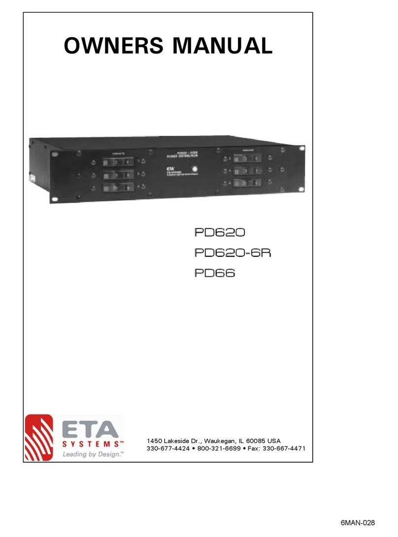
ETA Systems PD620 User manual

OWNER’S MANUAL
A Creative Light & Sound Company
1532 Enterprise Parkway, Twinsburg, OH 44087 USA
330-425-3388 • 800-321-6699 • Fax: 330-425-9700
http://www.etasys.com E-mail [email protected]
SYSTEMS
©
PD620
PD620-6R
PD66
TM
WARNING: Do not remove cover.No user serviceable parts inside.
Refer servicing and hook-up to qualified individuals only.
DANGER: Due to life threatening shock hazard, hook-up of this power
distribution pack must be made by qualified electricians only.
DANGER: Shock hazard, disconnect power before removing lid, or for
servicing.
ETA’s High Amperage Power Distribution is the professional system de-
signed for power hook-up of sound and lighting equipment.
HIGH AMP POWER DISTRIBUTION
PD620 / PD66
PD620 BACK
PD66 BACK
1
The PD66 and PD620 are designed for use on Three Phase (3Ø) WYE 120/
208V 4-pole 5-wire electrical service.With the ability to operate on Single
Phase (1Ø) 120/240V 3-pole 4-wire electrical service, (easily configured
internally).
DO NOT connect high voltage leg of DELTA type systems (the higher voltage
will damage sensitive equipment connected this way)—see NOTE below.
The PD66 can provide up to 140 amps total, 40 amps on one leg, 50 amps
each on remaining two legs (3Ø WYE 120/208V hook-up), OR *70 amps per
leg (two legs) (1Ø 120/240V hook-up <internal configuration>).
The PD620 can provide up to 120 amps total, 40 amps per leg (three legs)
(3Ø WYE 120/208V hook-up), OR *60 amps per leg (two legs) (1Ø 120/240V
hook-up <internal configuration>).
* When using Single Phase, incoming supply lines MUST be sized to accomodate 20
amps more per leg than highest per leg rating (PD66-70 amps, PD620-60 amps).
Minimum recommended AWG (AmericanWire Gauge) for electrical hook-up
(90°C Copper Wire).
3Ø 1Ø Position Color
#8 AWG #6 AWG Ground Green
#8 AWG #6 AWG Neutral White
#8 AWG #6 AWG Line 1 Black
#8 AWG #6 AWG Line 2 Red
#8 AWG N/C Line 3 Blue
Follow National Electrical Code, or Local Electrical Code when sizing input electrical supply
lines.
NOTE: Delta systems have one (1) leg at a higher potential (208 Volts) in reference to neutral,
sometimes termed “Crazy Leg”, or “High Leg” typically the orange color is reserved for
designation of this line. Do not conect this leg into the PD66 or PD 620.
2
SERVICE (SUPPLY) CONFIGURATIONS
3ØWYE 3Ø DELTA
120/208V 120/240V
L1-L2 = 208V L1-L2 = 240V
L2-L3 = 208V L2-L3 = 240V
L3-L1 = 208V L3-L1 = 240V
L1-N = 120V L1-N = 120V L1-N-L2 = 1Ø
L2-N = 120V L2-N = 120V
L3-N = 120V *L3-N = 208V
Ø = PHASE symbol * DO NOT connect this leg to the
PD66 or the
PD620
}
3
INPUT POWER CONNECTION FOR 120/240V SINGLE PHASE WIRING
(2 LEGS OF 120/240V 3Ø DELTA SYSTEM)
120/240 1Ø WIRING
• Move unit red wire from terminal block L3 terminal to L1 terminal
(L1 will now contain three red wires)
• Move unit black wire from terminal block L3 terminal to L2 terminal
(L2 will now contain three black wires)
• Increase supply lines gauge size to accomodate the
ADDITIONAL 20 amps (2400 VA) on each leg 4
INPUT POWER CONNECTION FOR 120/208V 3-PHASEWIRING
(120/208V 3Ø WYE SYSTEM)
INPUT
TERMINAL
BLOCK
INPUT
TERMINAL
BLOCK
PD66 (140 AmpTotal) PD620 (120 AmpTotal)
Breaker Outlet Breaker Outlet
No. 1 20 amp No. 1 (2) NEMA 5-20R No. 1 20 amp No. 1 (1) NEMA 5-20R
(Duplex Receptacle) (Duplex Receptacle)
No. 2 20 amp No. 2 (2) NEMA 5-20R No. 2 20 amp No. 2 (1) NEMA 5-20R
(Duplex Receptacles) (Duplex Receptacle)
No. 3 20 amp No. 3 (1) NEMA 5-20R No. 3 20 amp No. 3 (1) NEMA 5-20R
(Duplex Receptacle) (Duplex Receptacle)
No. 4 20 amp No. 4 (1) NEMA 5-20R No. 4 20 amp No. 4 (1) NEMA 5-20R
(Duplex Receptacle) (Duplex Receptacle)
No. 5 30 amp No. 5 (Internal Terminal Block) No. 5 20 amp No. 5 (1) NEMA 5-20R
(Accepts 3/4” strain relief) (Duplex Receptacle)
No. 6 30 amp No. 6 (Internal Terminal Block) No. 6 20 amp No. 6 (1) NEMA 5-20R
(Accepts 3/4” strain relief) (Duplex Receptacle)
PD66: Outlets No.5 and No. 6 (internal terminal blocks) access openings will
accpet 3/4” strain relief(s).
5
All designs and specifications are subject to change without notice.
Copyright © 1999 ETA Systems. 12/99 6MAN-028
A Creative Light & Sound Company
1532 Enterprise Parkway, Twinsburg, OH 44087 USA
330-425-3388 • 800-321-6699 • Fax: 330-425-9700
http://www.etasys.com E-mail [email protected]
SYSTEMS TM
©

This manual suits for next models

2

Other ETA Systems Power Distribution Unit manuals

ETA Systems PD11LV User manual

ETA Systems

ETA Systems PD11LV User manual

ETA Systems PD9L Owner's manual User manual

ETA Systems

ETA Systems PD9L Owner's manual User manual

ETA Systems PS220 User manual

ETA Systems

ETA Systems PS220 User manual

ETA Systems ETA-ECM2063 User manual

ETA Systems

ETA Systems ETA-ECM2063 User manual

ETA Systems PD9 User manual

ETA Systems

ETA Systems PD9 User manual

ETA Systems PD620 User manual

ETA Systems

ETA Systems PD620 User manual

ETA Systems ETA-PD8 User manual

ETA Systems

ETA Systems ETA-PD8 User manual

ETA Systems ETA-S20 User manual

ETA Systems

ETA Systems ETA-S20 User manual

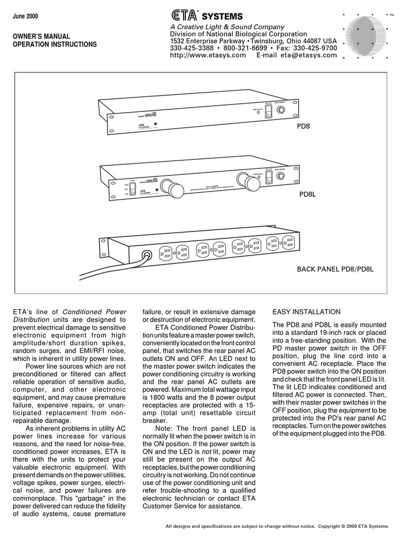
ETA Systems PD8 User manual

ETA Systems

ETA Systems PD8 User manual

ETA Systems PD11SP User manual

ETA Systems

ETA Systems PD11SP User manual

ETA Systems PD11LV User manual

ETA Systems

ETA Systems PD11LV User manual

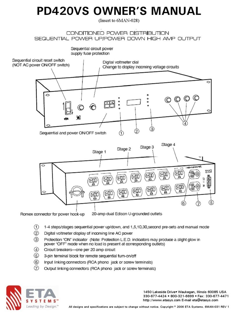
ETA Systems PD420VS User manual

ETA Systems

ETA Systems PD420VS User manual

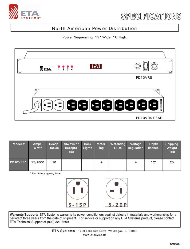
ETA Systems PD10VRS User manual

ETA Systems

ETA Systems PD10VRS User manual

ETA Systems PD8L User manual

ETA Systems

ETA Systems PD8L User manual

ETA Systems PD11LP User manual

ETA Systems

ETA Systems PD11LP User manual

ETA Systems PD11SS User manual

ETA Systems

ETA Systems PD11SS User manual

Popular Power Distribution Unit manuals by other brands

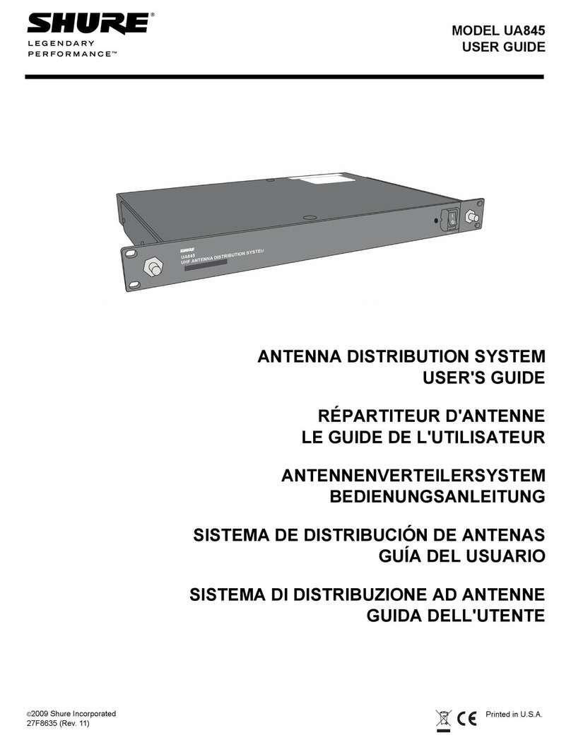
Shure UA845 user guide

Shure

Shure UA845 user guide

Denali POWERHUB2 installation instructions

Denali

Denali POWERHUB2 installation instructions

Clearfield FieldSmart installation manual

Clearfield

Clearfield FieldSmart installation manual

Atlas AP-S20 owner's manual

Atlas

Atlas AP-S20 owner's manual

GMG Power X-BLOCKER user manual

GMG Power

GMG Power X-BLOCKER user manual

LEGRAND HX3 125 A quick start guide

LEGRAND

LEGRAND HX3 125 A quick start guide

PANCONNECT SPOOK installation manual

PANCONNECT

PANCONNECT SPOOK installation manual

Minuteman RPM30241EV6 user manual

Minuteman

Minuteman RPM30241EV6 user manual

CYP RAX-PSU-12V Operation manual

CYP

CYP RAX-PSU-12V Operation manual

ABB Relion REB500 Product guide

ABB

ABB Relion REB500 Product guide

DONGAH ELECOMM CPRS-1400 installation manual

DONGAH ELECOMM

DONGAH ELECOMM CPRS-1400 installation manual

Tripp Lite SmartOnline SUPDMB20KHW quick guide

Tripp Lite

Tripp Lite SmartOnline SUPDMB20KHW quick guide

Black Box PDUMV24-S15-120V user manual

Black Box

Black Box PDUMV24-S15-120V user manual

Tripp Lite PDUBHV20 quick guide

Tripp Lite

Tripp Lite PDUBHV20 quick guide

Tripp Lite PDUMV30-ISO owner's manual

Tripp Lite

Tripp Lite PDUMV30-ISO owner's manual

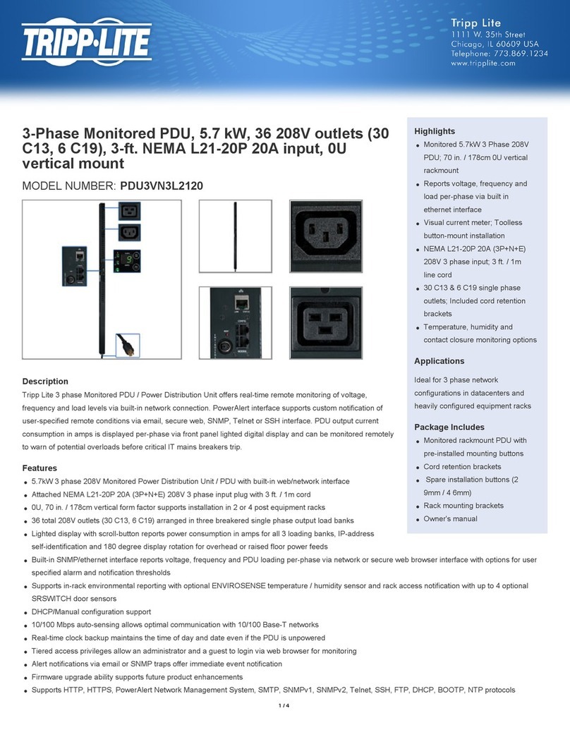
Tripp Lite PDU3VN3L2120 quick guide

Tripp Lite

Tripp Lite PDU3VN3L2120 quick guide

Atlas IED AP-S15HRIP owner's manual

Atlas IED

Atlas IED AP-S15HRIP owner's manual

JuiceGoose JG 11.0-20A owner's manual

JuiceGoose

JuiceGoose JG 11.0-20A owner's manual

manuals.online logo
manuals.online logoBrands
  • About & Mission
  • Contact us
  • Privacy Policy
  • Terms and Conditions

Copyright 2025 Manuals.Online. All Rights Reserved.