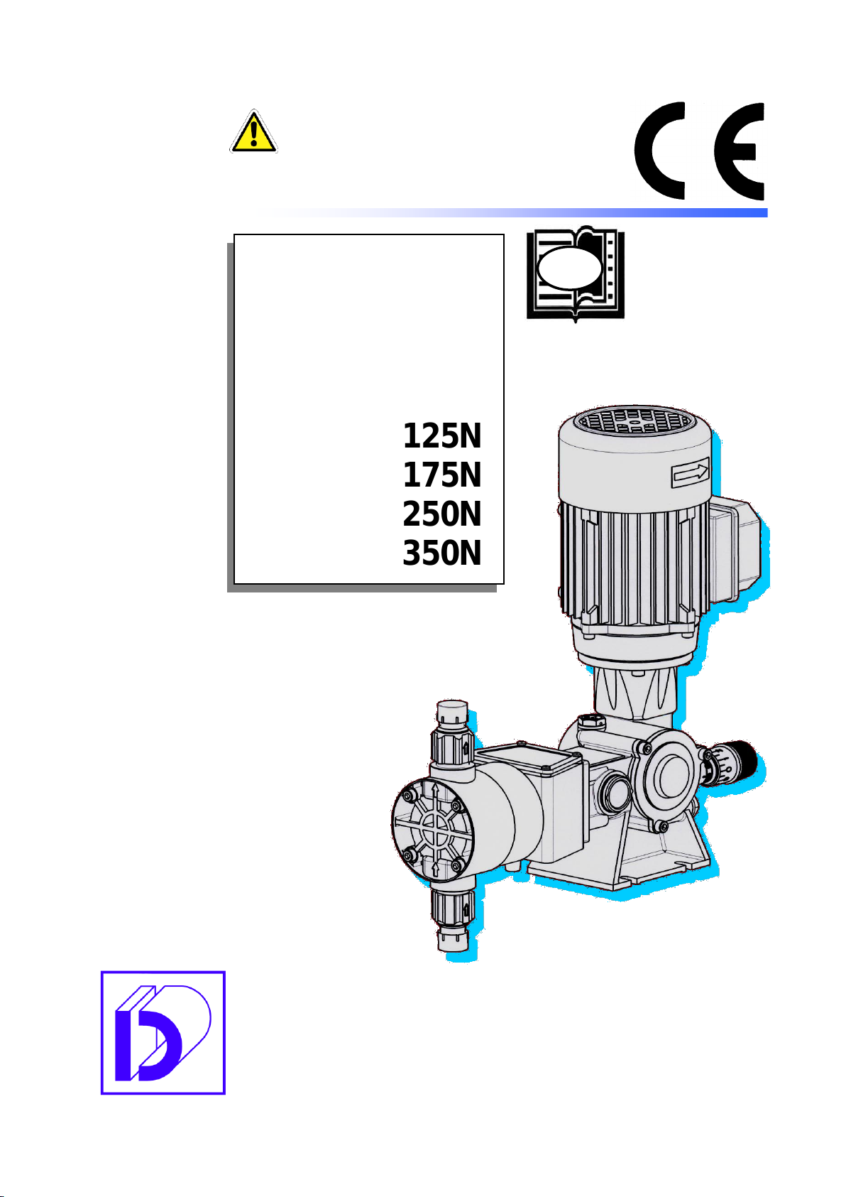
eta SR Series User manual

2014 EDITION
Reciprocating metering pump
with plunger
USE AND MAINTENANCE MANUAL
PUMPING HEADS
SPRING RETURN WITH
METERING PUMPS
SR Series
mod. A PLUNGER
A 125A
A 175A
A 125N
A 175N
A 250N
A 350N
EN
ATTENTION:
Industrial machinery for professional use.
These instructions are for qualified personnel
Translation of the
original instructions

DOSEURO®
XMPE0TMA125SST014 2014 EDITION
2
TABLE OF CONTENTS
Ref. Title Page
1 PREFACE 3
1.1 General prescriptions 3
2 TECHNICAL DATA 4
2.1 Technical data of pump 4
2.2 Sound vibration emitted by the pump 6
2.3 Material pertinence execution 6
3 OPERATIONS TO BE PERFORMED ON THE HEAD 7
3.1 Periodic check of head 7
3.2 Troubleshooting 8
3.3 Residual risks 9
4 HEAD DISASSEMBLY PLUNGER AND SEAL GASKET REPLACEMENT 10
4.1 Plunger disassembly and re-assembly 10
4.2 "PTFE” Gasket replacement and adjustment 11
4.3 Head with washing 11
4.4 Routine maintenance 12

DOSEURO®
XMPE0TMA125SST014 2014 EDITION
3
PREFACE
General prescriptions
This manual refers to the use and maintenance of the heads (hydraulic part) of the plunger spring
return metering pumps model A 125A/ A 175° / A 125N/ A 175N/ A 250N/ A 350N.
This manual is supplied together with the SR series pumps, model A/ B/ BR / SD / D use and
maintenance manual, to be consulted for any further information and which contains the CE
declaration of conformity.
1
1.1

DOSEURO®
XMPE0TMA125SST014 2014 EDITION
4
TECHNICAL DATA
Below are the tables with the technical data characteristic of each individual pump model.
Technical data of pump
The pressures indicated in the tables must never be exceeded in order to avoid any kind of
inconvenience. Should it be necessary to run the pump at a higher pressure, contact our technical
department.
The indicated flow rate value is subject to variations in view of the working pressure of the pumped liquid,
the viscosity and the conditions of installation.
The number of strokes per minute is calculated with 4-pole motors (~1400 rpm)
Characteristic data Model A 125A
FREQUENCY Hz
50
60
50
60
50
60
50
60
Head
Valve
Weig
ht
REDUCTION
RATIO
I(1/40)
F(1/24)
C(1/14,5)
B(1/12)
Max press.
bar
(Kg/cm2)
Typ
e
Ø
G.m.
Kg
STROKES min/1'
35
42
58
70
96
116
116
/
Flow rate l/h
A 125A - 11
2.4
2.8
4
4.8
6
8
8
/
10
AC 3
1/2"
7.5
A 125A - 18
6
7.2
10
12
16
20
20
/
10
AC 4
1/2"
7.5
A 125A - 25
13.2
15.8
22
26.4
36
44
44
/
10
AC 5
1/2"
7.5
A 125A - 31
18.7
22.4
31
37.2
51
62
62
/
10
AC 8
1/2"
7.5
A 125A - 38
30
36
50
60
82
100
100
/
9
AC 8
1/2"
8
A 125A - 47
47
56
78
93.6
129
156
156
/
5.5
AC 8
1/2"
8
Characteristic data Model A 175A
FREQUENCY Hz
50
60
50
60
50
60
Head
Valve
Weig
ht
REDUCTION RATIO
F(1/20)
C(1/14,5)
B(1/11)
Max press.
bar (Kg/cm2)
Type
Ø
G.m.
Kg
STROKES min/1'
70
84
96
116
120
/
Flow
rate l/h
A 175A - 38
83
99.6
115
138
144
/
10
AC 8
1/2"
10.5
A 175A - 47
130
156
180
216
226
/
8.5
AC 11
3/4"
10.5
Characteristic data Model A 125N
FREQUENCY Hz
50
60
50
60
50
60
50
60
HEAD
VALVE
REDUCTION RATIO
I (1/40)
F(1/24)
C(1/14,5)
B(1/12)
Max press.
bar (Kg/cm2)
AISI
PVC
Att. Ø
STROKES min/1'
35
42
58
70
96
116
116
/
AISI
PVC
Type
Type
G.m.
FLOW RATE l/h
A 125N - 6
/
/
0.8
1
1.3
1.6
1.6
/
20
10
AB 3
AC 3
1/2"
A 125N - 11
2.4
2.8
4
4.8
6
8
8
/
20
10
AB 3
AC 3
1/2"
A 125N - 18
6
7.2
10
12
16
20
20
/
20
10
AB 5
AC 4
1/2"
A 125N - 25
13.2
15.8
22
26.4
36
44
44
/
20
10
AB 5
AC 5
1/2"
A 125N - 30
18.7
22.4
31
37.2
51
62
62
/
14
10
AB 6
AC 8
1/2"
A 125N - 38
30
36
50
60
82
100
100
/
9
9
AB 8
AC 8
1/2"
A 125N - 47
47
56
78
93.6
129
156
156
/
5.5
5.5
AB 8
AC 8
1/2"
A 125N –47M
47
56
78
93.6
129
156
156
/
5.5
5.5
AB 11
AC 11
3/4"
2
ATTENTION!
2.1

DOSEURO®
XMPE0TMA125SST014 2014 EDITION
5
Characteristic data Model A 175N
FREQUENCY Hz
50
60
50
60
50
60
HEAD
VALVE
REDUCTION
RATIO
F(1/20)
C(1/14,5)
B
(1/11)
Max press.
bar (kg/cm2)
AISI
PVC
Att. Ø
STROKES
min/1'
70
84
96
116
120
/
AISI
PVC
Type
Type
G.m.
0.25
kW
0.37
kW
0.25
kW
0.37
kW
FLOW RATE l/h
A 175N - 6
1.3
1.56
1.7
2.11
2.2
/
20
20
/
/
AB 3
AC 3
1/2"
A 175N - 11
6
7.2
8
9.6
10
/
10
10
AB 3
AC 3
1/2"
A 175N - 18
17
20.4
24
28
30
/
AB 5
AC 4
1/2"
A 175N - 25
37
44.4
51
61.4
64
/
AB 6
AC 5
1/2"
A 175N - 30
52
62.4
72
86
90
/
AB 6
AC 8
1/2"
A 175N - 38
83
99.6
115
138
144
/
13
AB 8
AC 8
1/2"
A 175N - 47
130
156
180
216
226
/
8.5
13
8.5
AB 8
AC 8
1/2"
A175N-47M
130
156
180
216
226
/
8.5
13
8.5
AB 11
AC 11
3/4"
A 175N - 54
168
201.6
232
278
290
/
6.5
10
6.5
AB 13
AC 13
3/4"
A 175N - 64
236
283.2
326
391
408
/
4.5
7
4.5
7
AB 13
AC 13
3/4"
Characteristic data Model A 250N
FREQUENCY Hz
50
60
50
60
50
60
Head
Valve
REDUCTION RATIO
F(1/25)
C(1/14,5)
B(1/12.5)
Max press.
bar (kg/cm2)
AISI
PVC
Att. Ø
STROKES
min/1'
56
67
96
116
112
/
AISI
PVC
TYPE
TYPE
G.m.
0.55
kW
0.75
kW
0.55
kW
0.75
kW
FLOW RATE l/h
A 250N - 25
43
51.6
73
88
86
/
20
/
/
/
AB 6
AC 6
1/2"
A 250N - 38
96
115.2
164
197.5
192
/
20
/
/
AB 8
AC 8
1/2"
A 250N - 47
150
180
257
308
300
/
17
10
10
AB 13
AC 13
3/4"
A 250N - 54
192
230.4
329
395
384
/
13
17
AB 13
AC 13
3/4"
A 250N - 64
266
319.2
456
547.2
532
/
9.5
12
9.5
AB 17
AC 17
1"
A 250N - 76
383
459.6
656
787.8
766
/
6.5
8.6
6.5
8.6
AB 22
AC 22
1"
A 250N - 89
521
625.2
893
1071.7
1042
/
4.8
6.3
4.8
6.3
AB 22
AC 22
1"
Characteristic data Model A 350N
FREQUENCY Hz
50
60
50
60
50
60
Head
Valve
REDUCTION RATIO
F (1/25)
C(1/14,5)
B(1/12.5)
Max press.
bar (kg/cm2)
AISI
PVC
Att. Ø
STROKES min/1'
56
67
96
116
112
/
AISI
PVC
Type
Type
G.m.
FLOW
RATE
l/h
A 350N - 54
268
322
460
553
537
/
13
10
AB 13
AC 13
3/4"
A 350N - 64
372
446
638
766
744
/
9.5
9.5
AB 17
AC 17
1"
A 350N - 76
536
769
918
1103
1072
/
6.5
6.5
AB 22
AC 22
1"
A 350N - 89
729
874
1249
1498
1458
/
4
4
AB 27
AC 27
11/2"
Characteristic data Model AP-A 125N
FREQUENCY Hz
50
60
50
60
50
60
50
60
HEAD
VALVE
REDUCTION RATIO
I (1/40)
F(1/24)
C(1/14,5)
B(1/12)
Max press.
bar (Kg/cm2)
AISI
Att. Ø
STROKES min/1'
35
42
58
70
96
116
116
/
AISI
Type
G.m.
0.18 kW
0.25 kW
FLOW
RATE l/h
AP-A 125N - 8
1.1
1.3
1.9
2.2
3.1
3.7
3.7
/
95
230
AB 3
1/2"
AP-A 125N - 12
2.6
3.1
4.4
5.2
7.2
8.6
8.6
/
88
170
AB 3
1/2"
AP-A 125N - 14
3.6
4.2
6
7
9.9
11.8
11.8
/
65
125
AB 5
1/2"
AP-A 125N - 16
4.7
5.6
7.8
9.4
13
15.6
15.6
/
50
96
AB 5
1/2"

DOSEURO®
XMPE0TMA125SST014 2014 EDITION
6
Characteristic data Model AP-A 175N
FREQUENCY Hz
50
60
50
60
50
60
HEAD
VALVE
REDUCTION RATIO
F(1/20)
C(1/14,5)
B(1/11)
Max. pressure bar (kg/cm2)
AISI
Att. Ø
STROKES min/1'
70
84
96
116
120
/
AISI
Type
G.m.
0.25 kW
0.37 kW
FLOW
RATE l/h
AP-A 175N - 8
3.3
3.9
4.5
5.4
5.6
/
95
230
AB 3
1/2"
AP-A 175N - 12
7.4
8.8
10.1
12.1
12.6
/
AB 3
1/2"
AP-A 175N - 14
11.3
13.5
15.4
18.4
19.3
/
171
AB 5
1/2"
AP-A 175N - 16
14.7
17.6
20.1
24.1
25.2
/
75
131
AB 5
1/2"
AP-A 175N - 18
16.8
20.1
23
27.6
28.6
/
59
102
AB 5
1/2"
Characteristic data Model AP-A 250N
FREQUENCY Hz
50
60
50
60
50
60
Head
Valve
REDUCTION RATIO
F(1/25)
C(1/14,5)
B(1/12.5)
Max. pressure bar (kg/cm2)
AISI
Att. Ø
STROKES min/1'
56
67
96
116
112
/
AISI
TYPE
G.m.
0.55 kW
0.75 kW
FLOW RATE l/h
AP-A 250N - 12
8.5
10.2
14.5
17.4
16.9
/
95
230
AB 3
1/2"
AP-A 250N - 14
11.6
13.9
19.8
23.8
23.1
/
AB 5
1/2"
AP-A 250N - 16
15.1
18.2
25.8
31
30
/
196
AB 5
1/2"
AP-A 250N - 18
19.2
23
32.9
39.4
38.3
/
155
AB 5
1/2"
AP-A 250N - 20
23.7
28.4
40.6
48.7
47.3
/
126
AB 5
1/2"
AP-A 250N - 22
28.7
34.4
49.2
59
57.4
/
79
104
AB 6
1/2"
AP-A 250N - 25
37
44.4
63.5
76.2
74.1
/
61
80
AB 6
1/2"
SOUND VIBRATION EMITTED BY THE PUMP
Below are the results of the phonometric measurements carried out on the series pumps.
These tests were carried out by an external laboratory in compliance with Directives and Standards UNI
EN ISO 3744:2009 and Directive ISO 2002/44/EC.
Investigation table of phonometric pressure
Model A 125A / A 125 N
Condition of pressurised pump
Maximum sound emission
on the surface
Average level of
pressure on the surface.
Level of
sound power
dB(A) 71.7
dB(A) 67.9
dB(A) 71.4
Model A 175A / A 175N
Condition of pressurised pump
Maximum sound emission
on the surface
Average level of
pressure on the surface.
Level of
sound power
dB(A) 76.7
dB(A) 73.2
dB(A) 76.7
Model A 250N/ A 350N
Condition of pressurised pump
Maximum sound emission
on the surface
Average level of
pressure on the surface.
Level of
sound power
dB(A) 79.3
dB(A) 75.6
dB(A) 79.1
2.3

DOSEURO®
XMPE0TMA125SST014 2014 EDITION
7
OPERATIONS TO BE PERFORMED ON THE HEAD
Periodic check of the head
Failures or malfunctions may occur due to negligence leading to extraordinary maintenance: proceeding
with a periodic visual check, as described in the SR REDUCER manual, preventive maintenance
chapter. It is, at times, possible to avoid the arising of situations that require extraordinary maintenance.
In the presence of these anomalies we recommend readily
intervening in order to avoid safety problems, a reduced flow
rate and reduced efficiency of the pump.
Summarising, the checks to be carried out are:
Periodic checks of the pumping head must be carried out to
ensure that the pump is safe and operating correctly.
Particular attention must be taken if the head installed is
made of plastic as it is more sensitive to temperature
variations and settling phenomena.
Check for dosed liquid leaks from the valves or from the
plunger gaskets.
Troubleshooting
This chapter describes some inconveniences that may arise during machine use.
We propose some possible interventions: it is good practice to initially attempt to resolve a
problem applying the most simple of solutions. Never attempt repairs if unsure of what you are
about to do: greater damage may be caused.
The indications described in the following table help in the event of troubleshooting.
TROUBLESHOOTING
Inconveniences
Causes
Solutions
Low delivery pressure
Low flow rate
1 - Clogged suction system:
Clean suction filter. Check the
suction piping and the feed tank
for obstructions or partially closed
valves
2 - Worn safety relief/vent valve
seat:
Check the safety relief/vent valve,
if the liquid leaks - switch-off the
pump and check
Low delivery pressure
Low flow rate
3 - pump not completely primed
(air bubble in the suction pipe):
Excessive suction height, respect
NPSHr value, install a suction
dampener
ATTENTION!
3
3.1
3.2
ATTENTION!

DOSEURO®
XMPE0TMA125SST014 2014 EDITION
8
TROUBLESHOOTING
Inconveniences
Causes
Solutions
Low delivery pressure
Low flow rate
4 –incorrectly connected
motor:
Check the motor plate again for
the correct wiring sequence.
Check the phases.
5 - dirty pump valves:
Inspect valve units. Clean or
replace the components if
necessary.
6 - Damaged plunger seal
gasket.
Air inlet through plunger seals.
Scratched plunger
Replace the seal gaskets or the
plunger
7 - air entering the head
Verify the presence of inlet air in
the suction pipe. Check junctions
between pipes, seals around the
valve stems, and the connections
of the instruments.
Check the diameter and piping
route.
8 - insufficient suction pressure
Increase the suction pressure.
Reduce the suction height or
increase the liquid level in the
feed tank.
9 - Circuitous piping route with
the presence of chokes; pipe
inner diameter smaller than the
valve passage area;
Check diameter and piping route
Dosed liquid leaking from hole
underneath the lantern.
Damaged plunger seal gasket.
Scratched plunger
Replace the seal gaskets or the
plunger.
Excessive noise
1 - air entering the head
Verify the presence of inlet air in
the suction pipe. Check junctions
between pipes, seals around the
valve stems, and the connections
of the instruments.
If the air is entering through the
stuffing box, adjust or replace it.
2 - foreign material inside valve
Inspect valve units. Clean or
replace the components if
necessary.
3 - excessive lifting of valves
Replace the worn parts
4 - safety relief valve or other
accessories in delivery piping
cause noise
A quick closing of the valve,
solenoid valve or faucet will
produce a water hammer. This
pressure wave is transmitted to
the pump resulting in noise.
A pulsation dampener before the
back pressure valve may be
requested. A different type of
valve may be requested.

DOSEURO®
XMPE0TMA125SST014 2014 EDITION
9
ROTATION
OF PLUNGER
LOOSENING OF
PLUNGER
BLOCKING DOWELS
Residual risks
Any leaks of the pumped liquid from the plunger gaskets, due to wear, must be channelled and
collected for disposal.
HEAD DISASSEMBLY PLUNGER AND SEAL GASKET REPLACEMENT
Before intervening on the metering pump or on the piping, the necessary precautions must be taken so
that the pumped product, especially if harmful, does not endanger personnel or the surrounding elements.
BEFORE INTERVENING PERSONNEL MUST ENSURE THAT:
The pump has stopped and has been disconnected from the mains power supply.
The pump head and the plant are de-pressurised and drained of any liquid.
The pump has reached such a temperature to be able to safely move it.
Proceed as follows, using the sections of the pumping heads to identify the components and their
order of assembly:
Plunger disassembly and re-assembly
The plunger is blocked on the slide by means of two dowels,
one visible in the upper part and the other hidden in the lower
part.
Proceed as follows to disassemble the plunger:
Remove the covering protections from the lantern.
Loosen the screws fixing the head to the lantern and
remove it.
Where present, remove the gasket ring from the head.
Check the gaskets for wear or damage and replace
them.
Loosen the screws inside the lantern blocking it to the
pump body.
Remove the lantern.
Loosen the visible dowel.
Hold the plunger and turn it until the second dowel is
visible, then loosen it.
Once the operations are complete, carry out the disassembly operations in reverse order to
reassemble the components.
The plunger must be reassembled taking care to tighten the two dowels with the same force so
that the plunger assembly is coaxial with the slide.
3.3
4
ATTENTION!
4.1
ATTENTION!

DOSEURO®
XMPE0TMA125SST014 2014 EDITION
10
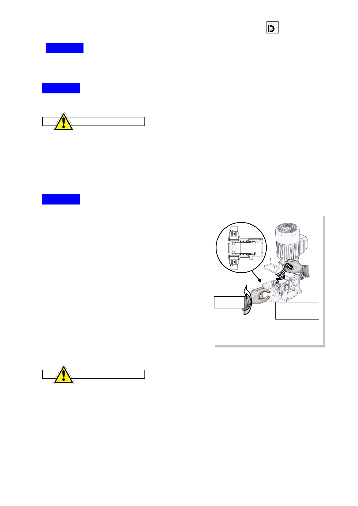
"PTFE" GASKET REPLACEMENT AND ADJUSTMENT
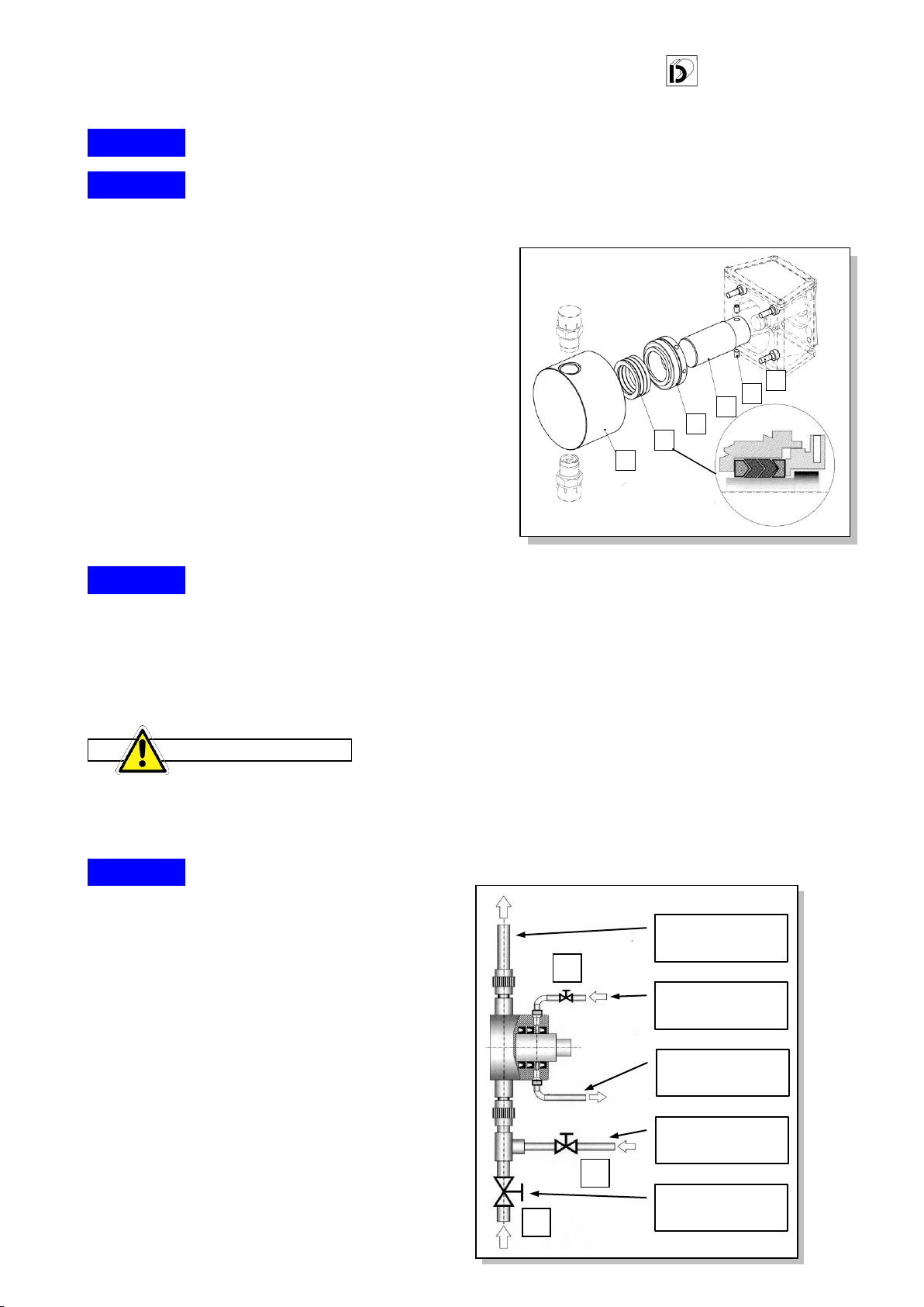
Replacement of gasket pack (execution head 21)
After maintenance, proceed as follows:
Disconnect the pumping head 1from the system and
from the lantern on the metering pump.
Wash the pumping head so that the operator can safely
handle the component.
Loosen the locking ring 11 until completely removed.
Check the plunger for wear 2, and replace it if
scratched or worn. Do this by loosening the dowels 15.
Extract the ruined gasket pack 3, insert the new one
inside the pumping head paying attention to the
orientation direction of the gaskets.
Tighten the locking ring 11 until the gaskets touch,
without tightening further.
Insert the pumping head 1on the plunger, push it up to
the lantern and fix it with the screws 4.
Adjustment and compression of the "PTFE" gaskets
Work as follows to make any adjustments:
Connect the metering pump to the system piping and bring the pressure up to speed.
Acting on locking ring 11, gradually fasten to compress the gaskets making sure there is no
liquid leaking.
The gasket pack control and adjustment operations must be performed periodically. In
executing the adjustment operation, the operator must not excessively fasten the locking ring
in order to preserve the integrity of the gaskets.
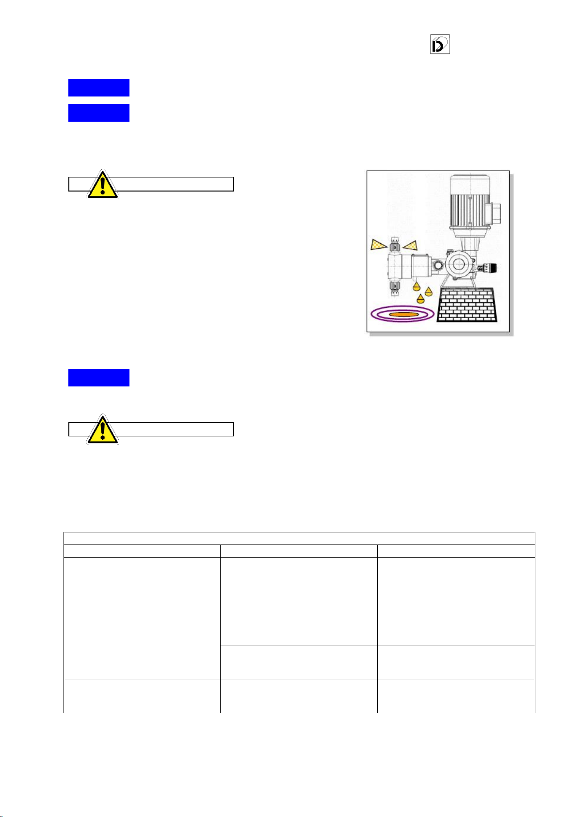
HEAD WITH WASHING
This type of head, that provides for the washing of the
internal parts, is used when the liquid to be dosed can
create abrasion or solidification.
Typical representation of the system to execute
washing.
Washing the seal gaskets
Let the water continuously flow through the area
containing the seal gaskets, with a flow rate of 40/50
l/h, at a pressure of 0.5/1 bar.
It is essential to continuously wash the gaskets as it
helps remove any fouling and stops the product from
solidifying and damaging the seal profiles.
4.2
4.2.1
ATTENTION!
4.2.2
4.3
1
3
11
4
2
15
A
B
C
SUCTION SHUT-OFF
VALVE
FROM THE WATER
MAINS FOR HEAD
WASHING
FROM THE WATER
MAINS FOR GASKET
WASHING
PIPING FOR
DRAINING
WASHING
DELIVERY PIPING TO
SYSTEM

DOSEURO®
XMPE0TMA125SST014 2014 EDITION
11
Pumping head washing
Connect the piping as per the diagram to wash the gaskets and head.
The needle valve "C" must remain open throughout pump operation.
After dosing, before stopping the pump, close valve "A", at the same time, open valve "B" and valve
"C" (always open) of the gasket area, let the washing water circulate for about 3/4 minutes.
After this time, stop the pump and let the washing water run until it is clear.
After washing, close valves "B" and "C" and open valve "A" to allow pumping the product.
Open valve "C" before restarting the pump.
Carry out this procedure especially when the pump is to be stopped for a long time after
completing the working process.
ROUTINE MAINTENANCE (ref. UNI 11063)
The table shows the parts subject to greater wear which therefore require routine maintenance. We
recommend verification and replacement, if necessary.
Maintenance
period
Head
Valve unit
Gaskets
Plunger
Plastic
Metal
Hours
Half-yearly
X
X
X
X
In case the pump is used continuously and in particularly harsh conditions, we recommend reducing the
verification times.
4.4
ATTENTION!

DOSEURO®
XMPE0TMA125SST014 2014 EDITION
12
For a better use of your metering pump, choose:
DOSEURO®S.r.l ACCESSORIES.
Request them to our Sales Department
Doseuro®S.r.l.
The Right Dosing Choice
Via G. Carducci, 141 - 20093 Cologno Monzese (Mi) - Italy
Tel. +39 0227301324 - Fax. +39 0226700883
http://www.doseuro.com
Cert. No. 5942
ETA Ekipman Teknoloji Ar. Sis. San. Tic. Ltd. Şti.
www.etaekipman.com blog.etaekipman.com
Tel:0 216 540 99 64 Fax:0 216 540 99 68
This manual suits for next models
6
Table of contents
Other eta Water Pump manuals
Popular Water Pump manuals by other brands

Ismatec
Ismatec FIXO operating manual

BWT
BWT PEARL HPT 09 instruction manual

Einhell Royal
Einhell Royal HWA 810 operating instructions

Wilo
Wilo Sub TWI 4 Installation and operating instructions

Garland
Garland AMAZON 300 E instruction manual

Standart
Standart ECO SNM Series Instruction for operation and maintenance