ETAS ES1336.1 User manual

ES1336.1 Angle Synchronous Measurement Board
User’s Guide

2
Copyright
The data in this document may not be altered or amended without special
notification from ETAS GmbH. ETAS GmbH undertakes no further obligation
in relation to this document. The software described in it can only be used if
the customer is in possession of a general license agreement or single license.
Using and copying is only allowed in concurrence with the specifications
stipulated in the contract.
Under no circumstances may any part of this document be copied, repro-
duced, transmitted, stored in a retrieval system or translated into another
language without the express written permission of ETAS GmbH.
© Copyright 2018 ETAS GmbH, Stuttgart
The names and designations used in this document are trademarks or brands
belonging to the respective owners.
V1.0.0 R03 EN - 07.2018

Contents 3
Contents
1Introduction . . . . . . . . . . . . . . . . . . . . . . . . . . . . . . . . . . . . . . . . . . . . . . . . . . . . . 5
1.1 Applications . . . . . . . . . . . . . . . . . . . . . . . . . . . . . . . . . . . . . . . . . . . . . . . 6
1.2 Features . . . . . . . . . . . . . . . . . . . . . . . . . . . . . . . . . . . . . . . . . . . . . . . . . . 6
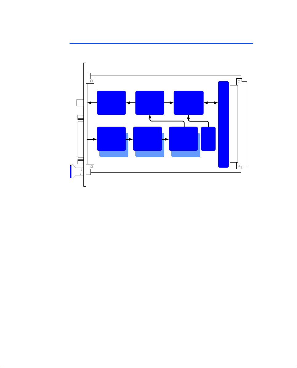
1.3 Block Diagram . . . . . . . . . . . . . . . . . . . . . . . . . . . . . . . . . . . . . . . . . . . . . . 8
1.4 Taking the Product Back and Recycling . . . . . . . . . . . . . . . . . . . . . . . . . . . 9
2Hardware . . . . . . . . . . . . . . . . . . . . . . . . . . . . . . . . . . . . . . . . . . . . . . . . . . . . . . 11
2.1 Signal Inputs . . . . . . . . . . . . . . . . . . . . . . . . . . . . . . . . . . . . . . . . . . . . . . 11
2.1.1 Input Circuitry . . . . . . . . . . . . . . . . . . . . . . . . . . . . . . . . . . . . . 11
2.1.2 Electrical Strength and Impedance Converter . . . . . . . . . . . . . . 11
2.1.3 Threshold Comparison . . . . . . . . . . . . . . . . . . . . . . . . . . . . . . . 12
2.1.4 Ground and Shielding. . . . . . . . . . . . . . . . . . . . . . . . . . . . . . . . 12
2.2 Synchronization Signals . . . . . . . . . . . . . . . . . . . . . . . . . . . . . . . . . . . . . . 13
2.3 Angle Windows . . . . . . . . . . . . . . . . . . . . . . . . . . . . . . . . . . . . . . . . . . . . 13
2.4 Diagnostic Outputs . . . . . . . . . . . . . . . . . . . . . . . . . . . . . . . . . . . . . . . . . 15
2.5 Measurement Modes . . . . . . . . . . . . . . . . . . . . . . . . . . . . . . . . . . . . . . . 15
2.6 Start of Angle Measuring after Initialization . . . . . . . . . . . . . . . . . . . . . . . 17
3Pin Assignment and Display Elements . . . . . . . . . . . . . . . . . . . . . . . . . . . . . . . . . 19
3.1 “Input 0-19” Connector . . . . . . . . . . . . . . . . . . . . . . . . . . . . . . . . . . . . . 19
3.2 “DIAG 0-7” Connector . . . . . . . . . . . . . . . . . . . . . . . . . . . . . . . . . . . . . . 20

Contents4
3.3 LEDs for Status Display . . . . . . . . . . . . . . . . . . . . . . . . . . . . . . . . . . . . . . 21
4Accessories. . . . . . . . . . . . . . . . . . . . . . . . . . . . . . . . . . . . . . . . . . . . . . . . . . . . . 23
4.1 Digital Output Cable with BNC . . . . . . . . . . . . . . . . . . . . . . . . . . . . . . . . 23
5Technical Data . . . . . . . . . . . . . . . . . . . . . . . . . . . . . . . . . . . . . . . . . . . . . . . . . . 25
6ETAS Contact Addresses. . . . . . . . . . . . . . . . . . . . . . . . . . . . . . . . . . . . . . . . . . . 27
Index . . . . . . . . . . . . . . . . . . . . . . . . . . . . . . . . . . . . . . . . . . . . . . . . . . . . . . . . . 29

Introduction 5
1 Introduction
This User’s Guide describes the ES1336.1 Angle Synchronous Measurement
Board.
It consists of the following chapters:
• Introduction
• "Hardware" on page 11
• "Pin Assignment and Display Elements" on page 19
• "Accessories" on page 23
• "Technical Data" on page 25
• "ETAS Contact Addresses" on page 27
CAUTION!
Some components of the ES1336.1 Angle Synchronous Measure-
ment Board may be damaged or destroyed by electrostatic dis-
charges. Please keep the board in its storage package until it is
installed.
The ES1336.1 Angle Synchronous Measurement Board should
only be taken from its package, configured and installed at a
working place that is protected against static discharge.
WARNING!
The components, connectors and conductors of the ES1336.1
Angle Synchronous Measurement Board may carry dangerous
voltages. These voltages may even exist when the ES1336.1 is not
installed in the ES4100, ES4105 or ES4300 or the ES4100, ES4105
or ES4300 is powered off.
Make sure that the ES1336.1 is protected against contact during
operation. Disconnect all connections to the ES1336.1 before
removing the board.

Introduction6
1.1 Applications
The ES1336.1 Angle Synchronous Measurement Board is used to acquire and
evaluate digital ECU signals.
This means:
• The acquisition and evaluation of speed-synchronous (= angle-synchro-
nous) signals such as injection and ignition signals.
• The acquisition and evaluation of asynchronous (usually pulse-width
modulated) signals such as exhaust gas recirculation and canister purge
valve.
• The acquisition and evaluation of static (switch) signals such as ventila-
tor control and malfunction indicator lamp.
A whole range of measurement modes is available for this, e.g. pulse
integration and pulse count, detection of peak amplitudes and the measuring
of rise and fall times (in piezo injector control).
1.2 Features
The ES1336.1 Angle Synchronous Measurement Board has the following fea-
tures:
• 20 independent input channels
• Two inputs for battery voltages which are used for the threshold values
when digitizing input signals
• Eight diagnostic outputs for monitoring digitized, FPGA-internal signals
(e.g. in an oscilloscope).
• Speed/angle clock generator module
• Many speed-synchronous and time-synchronous measurement modes

Introduction 7
The following figure shows the front panel of the ES1336.1 Angle Synchro-
nous Measurement Board.
Fig. 1-1 Front Panel of the ES1336.1 Angle Synchronous Measurement
Board
ES1336.1
INPUT 0-19 DIAG 0-7
L0ER L1
ETAS

Introduction8
1.3 Block Diagram
Fig. 1-2 shows the block diagram of the ES1336.1 Angle Synchronous Mea-
surement Board.
Fig. 1-2 Block Diagram of the ES1336.1 Angle Synchronous Measure-
ment Board
CH19CH19
Impedance
Converter
CH0
CH19
VMEbus Interface
CH0
Processor
(FPGA)
Diagnostic
Outputs
Edge
Recognition
(FPGA)
Overvoltage
Protection
CH0
A/D
Converter
CH0
Serial
Flash

Introduction 9
1.4 Taking the Product Back and Recycling
The European Union has passed a directive called Waste Electrical and Elec-
tronic Equipment, or WEEE for short, to ensure that systems are setup
throughout the EU for the collection, treating and recycling of electronic
waste.
This ensures that the devices are recycled in a resource-saving way represent-
ing no danger to health or the environment.
Fig. 1-3 WEEE Symbol
The WEEE symbol on the product or its packaging shows that the product
must not be disposed of as residual garbage.
The user is obliged to collect the old devices separately and return them to the
WEEE take-back system for recycling.
The WEEE directive concerns all ETAS devices but not external cables or batter-
ies.
For more information on the ETAS GmbH Recycling Program, contact the ETAS
sales and service locations (see "ETAS Contact Addresses" on page 27).

Introduction10

Hardware 11
2 Hardware
This chapter describes the individual function units of the ES1336.1 Angle Syn-
chronous Measurement Board in more detail. These are:
• "Signal Inputs" on page 11
• "Synchronization Signals" on page 13
• "Angle Windows" on page 13
• "Diagnostic Outputs" on page 15
• "Measurement Modes" on page 15
2.1 Signal Inputs
This section describes the 20 signal inputs of the ES1336.1 Angle Synchronous
Measurement Board.
2.1.1 Input Circuitry
The signals applied at the front-facing “Input 0-19” connector are routed to a
12-bit A/D converter via an overvoltage protection and an impedance con-
verter. This works with a sampling frequency of 12.5 MHz. Both battery volt-
ages are routed to a 10-bit A/D converter which works with a sampling
frequency of 78.125 kHz.
In the FPGA, the data flow is acquired by the A/D converter and the input
voltages measured.
Fig. 2-1 Input Circuitry of the ES1336.1 Angle Synchronous Measure-
ment Board
2.1.2 Electrical Strength and Impedance Converter
The 20 input channels are designed for input voltages from 0 – 40 V and are
protected against voltage up to ±60 V. By using impedance converters, an
input impedance of 1 MΩis attained.
Input
+
-ADC FPGA

Hardware12
The two battery voltage inputs are designed for a voltage range of 0 – 60 V
and are also protected against voltage up to ±60 V. The input impedance is
100 kΩ.
2.1.3 Threshold Comparison
Each of the 20 input signals of the ES1336.1 Angle Synchronous Measurement
Board is compared to two threshold values in the FPGA. This comparison leads
to a conversion of the analog input signal to digital 0/1 information.
The upper threshold (0 →1) is 2/3 UBatt, the lower threshold (1 →0) is 1/
3 UBatt (see Fig. 2-2). This method provides optimum interference immunity
during edge detection.
The thresholds can be configured by software – the following three possibili-
ties are available:
• Comparison to 1/3 UBatt_A and 2/3 UBatt_A (via front panel)
• Comparison to 1/3 UBatt_B and 2/3 UBatt_B (via front panel)
• Comparison to any two thresholds which can be configured by soft-
ware (RTIO).
Fig. 2-2 Digitizing the Input Signal
2.1.4 Ground and Shielding
On the ES1336.1 Angle Synchronous Measurement Board, VME ground and -
UBatt (vehicle ground) are connected.
The shielding is at front panel potential and thus at protective earth.
UBatt
2/3*UBatt
1/3*UBatt

Hardware 13
2.2 Synchronization Signals
The ES1336.1 Angle Synchronous Measurement Board can obtain current
angle information from the ES1335.1 Arbitrary Signal Generator Board via the
VME backplane.
This crankshaft angle clock signal consists of three parts (see Fig. 2-3):
• The synchronization signal at 0 °CA
• The actual clock signal
• The signal for the direction of rotation (DOR)
A “high” level of the DOR signal means “rotation with an increasing crank-
shaft angle”; a “low” level means “rotation with a decreasing crankshaft
angle”.
The following figure shows the course of the three signals during a camshaft
rotation.
Fig. 2-3 The Three Components of the Crankshaft Angle Clock Signal
The ES1336.1 Angle Synchronous Measurement Board can also be used as
master, i.e. it issues the angle clock signal on the VME backplane. The defini-
tion of whether the particular ES1336.1 works as an angle clock master or
slave is made in LABCAR-RTC (RTIO).
2.3 Angle Windows
For measurements in speed-synchronous mode, an angle window for measur-
ing is always determined by the RTIO parameters “CS Angle Lower Limit” and
“CS Angle Upper Limit”.
Three angle windows can be defined per hardware channel – the maximum
size of an angle window is 720 °CA.
V
Low
High
Synchronization
α
0 °CA 720 °CA
V
Low
High
V
Low
High
Clock
Direction of Rotation

Hardware14
Calculating the Measure Values
The measure values start being calculated once the upper end of the angle
window has been reached; the result is transferred directly to the DPRAM. This
ensures that the data in the DPRAM is up-to-date and consistent.
Fig. 2-4 illustrates this using the measuring of injection signals in an 8-cylinder
engine as an example: a cylinder is measured within an angle window of
around 70° before TDC to 30° after TDC; then the data of the relevant cylinder
is transferred to the DPRAM.
Fig. 2-4 Angle Window for Measuring Injection Signals
Cyl. 1
Cyl. 2
Cyl. 3
Cyl. 4
Cyl. 5
Cyl. 6
Cyl. 7
Cyl. 8
0 °CA 360 °CA 720 °CA
90 °CA 180 °CA 270 °CA 450 °CA 540 °CA 630 °CA

Hardware 15
2.4 Diagnostic Outputs
To visualize the digitized input signals, the front panel features eight diagnostic
outputs.
Each of the following signals can be issued on channels “Out 0”...“Out 7” –
configuration takes place in RTIO.
• Digitized input signal 0 (signal after the comparator)
• ......
• Digitized input signal 19 (signal after the comparator)
• Angle clock synchronization signal (0 °CA trigger signal, see Fig. 2-3
on page 13)
ETAS can supply a corresponding cable with eight BNC connectors (for output-
ting the signals, for example on an oscilloscope) (see "Accessories"
on page 23).
2.5 Measurement Modes
The following measurement modes are available for the ES1336.1 Angle Syn-
chronous Measurement Board. A detailed description of the individual meth-
ods is contained in the User's Guide for LABCAR-RTC V2.2 Real-Time
Execution Connector.
Pulse-Width Measurements
• Hightime [μs]
•Lowtime[μs]
Additive Pulse-Width Measurements
• Additive Hightime [μs]
• Additive Lowtime [μs]
Pulse-Width Measurements with Enable or Validation Signal
• Hightime using H-Enable [μs]
• Hightime using L-Enable [μs]
• Lowtime using H-Enable [μs]
• Lowtime using L-Enable [μs]
• Hightime using H-Validate [μs]
• Hightime using L-Validate [μs]
• Lowtime using H-Validate [μs]

Hardware16
• Lowtime using L-Validate [μs]
Frequency and Cycle Time Measurements
• Frequency --/-- [Hz]
• Cycle Time --/-- [μs]
Duty Cycle Measurements
• Duty Cycle L/(L+H) --/--
• Duty Cycle H/(L+H) --/--
Measuring Edges: Angle Stamp
• Rising Edge --/-- [deg]
• Falling Edge --\-- [deg]
Measuring Edges: Time Stamp
• Time Stamp of n-th rising edge [μs]
• Time Stamp of n-th falling edge [μs]
Measuring Edges: Rise and Fall Time
• Rising Time [μs]
• Falling Time [μs]
Pulse Count
• Number of Low-Pulses
• Number of High-Pulses
• Total Number of L-Pulses
• Total Number of H-Pulses
Measuring Integrals
• Integral U*dt [V*μs]
Voltage Measurements
• Input Voltage [V]
• Peak Amplitude [V]

Hardware 17
2.6 Start of Angle Measuring after Initialization
The ES1336.1 needs three camshaft revolutions after initialization until it is
synchronized with the ES1335 Arbitrary Signal Generator Board. No measure
values are issued during this time.
Initialization is executed:
• after downloading the model code to the simulation target
• after a change of the RTIO setting in online mode

Hardware18

Pin Assignment and Display Elements 19
3 Pin Assignment and Display Elements
This chapter contains a description of the pins and LEDs on the front panel of
the ES1336.1 Angle Synchronous Measurement Board.
3.1 “Input 0-19” Connector
The input signals and battery voltages are applied at the “Input 0-19” connec-
tor. This connector is a DSUB, 25-pin (male) connector.
Fig. 3-1 shows the pin assignment (view from the plug-in side).
Fig. 3-1 “Input 0-19” Connector
The pin assignment is as follows:
Tab. 3-1 “Input 0-19” Pin Assignment
Pin Signal Pin Signal
1 IN_CH0 14 IN_CH13
2 IN_CH1 15 IN_CH14
3 IN_CH2 16 IN_CH15
4 IN_CH3 17 n.c.
5 IN_CH4 18 n.c.
6 IN_CH5 19 IN_CH16
7 IN_CH6 20 IN_CH17
8 IN_CH7 21 IN_CH18
9 IN_CH8 22 IN_CH19
10 IN_CH9 23 +UBatt_A
11 IN_CH10 24 +UBatt_B
12 IN_CH11 25 -UBatt (ground)
13 IN_CH12 Housing Protective earth
14 1
25 13

Pin Assignment and Display Elements20
3.2 “DIAG 0-7” Connector
Up to 8 FPGA signals can be led through to the “DIAG 0-7” connector for
diagnostic purposes.
The connector is a Lemo EXB.1B.310.HLN (female) connector.
Fig. 3-2 shows the pin assignment (view from the plug-in side).
Fig. 3-2 “DIAG 0-7” Connector
The pin assignment is as follows:
Tab. 3-2 “DIAG 0-7” Pin Assignment
Pin Signal Pin Signal
1GND 7Out5
2Out0 8GND
3Out1 9Out6
4Out2 10Out7
5 Out 3 Housing Protective earth
6Out4
1
23
4
10
5
67
8
9
Table of contents
Other ETAS Measuring Instrument manuals

ETAS
ETAS FETK-T3.0 User manual

ETAS
ETAS ES600 Series User manual

ETAS
ETAS BR XETK-S1.0 User manual

ETAS
ETAS CBN100.1 User manual

ETAS
ETAS FETK-T5.0A User manual

ETAS
ETAS ETK-T2.2 User manual

ETAS
ETAS BR-XETK-S1.0 User manual

ETAS
ETAS BR XETK-S3.0 User manual

ETAS
ETAS MDA V8 User manual

ETAS
ETAS XETK-S20.1B User manual