ETC IRIDEON Assembly instructions

TECHNICAL ASSISTANCE
The AR6 luminaire is designed to be a low maintenance lighting
instrument. For further assistance or questions regarding this lumi-
naire, please contact the ETC Technical Support staff in Middle-
ton, Wisconsin U.S.A. at 608-831-4116 or toll-free at 800-688-
4116.
Before Starting
Items required for installation, but not supplied:
• #2 Phillips screwdriver
• 3 each 18 -10 AWG wire nuts
• Hammer and 4 each 1-1/4” nails or 1-1/4” wood screws for
wood framed installations.
• 4 each 1-1/4” sheet metal screws for metal framed installa-
tions.
Site Preparation
AC and Data Power Wiring
Note: The installation contractor is responsible for compliance
with local electrical codes.
Data and AC power are to be routed through separate conduit.
Separate junction boxes are provided on the luminaire housing for
connection of AC and data.
WARNING: Do not attempt to connect equipment with
power applied.
Input Rating:
100-120V @ 3A max. 208-277V @ 2A max.
Cable Specifications
AC Power Input
Wire Gauge: 18-10 Awg 3-conductor *(.82 - 5.37mm2x3-cond.)
Rating: 300V
Connect as follows:
Data Input
Wire Gauge: 24 AWG
Description: Category 5 solid conductor, shielded, twisted pairs
Recommended Cable: Belden 1589A Belden 1584A
Alpha 9504CS Manhattan/CDT M19094
Wire Connection
Black *(Brown) AC Line
White *(Blue) AC Neutral
Green or bare *(Grn/Yel) Ground
*International (Harmonized)
Standard
IRIDEON®Rough-In Housing Installation Sheet for
AR6™Recessed Luminaire

INSTALLATION
The luminaire is designed to fit between ceiling rafters or wall
studs with 16” (400mm) centers. UL codes require a minimum
of 1/2” (12mm) clearance on all sides from framing.
Adjustable mounting brackets are provided to accomodate a
range of openings not to exceed 24” (610mm). Brackets can be
installed on the long or short sides of the housing to aid installa-
tion. Maximum bracket reach is 16” x 24” (406mm x 610mm).
Note: Maintain 1/2” to 3/4” space between bottom of luminaire
housing and outside surface of ceiling material (normal thickness
of sheetrock or ceiling tile) to allow for proper fit of trim cover.
For wood stud framing, align bottom of bracket with bottom of
stud and hammer prongs into stud. Secure with 1-1/4” nail or
wood screw through hole in each bracket.
For metal stud framing, bend bracket prongs flat and secure in
place with 1-1/4” sheet metal screw through hole in each bracket.
For suspended ceiling installations, the adjustable mounting
brackets are notched to fit into ceiling tile support tracks. Place in
position and tighten set screw.
Note: For additional information on suspended ceiling consider-
ations and use of mounting bracket extensions, see back page.
13"
(330mm)
21"
(533mm)
16"
(406mm) 24"
(610mm)
Enclosure hole size is 14" x 22" (+/- 1")
356mm x 559mm (+/- 25mm)
10.5"
(267mm)
For metal framed structures, flatten pron
g
s
and secure with screws.
For wood
framin
g
,
hammer pron
g
s
into studs, then
secure with
screws throu
g
h
hole.
Notches set over suspended ceilin
g
tracks.
Ti
g
hten screws a
g
ainst tracks to secure.
Mountin
g
Bracket
Hammer pron
g
s into
wooden studs. Secure
with nail or wood screw.
Ali
g
n
bracket with
stud bottom.
Mountin
g
Bracket
Ti
g
hten set screw
Ceilin
g
Tile
Support Track

Incoming AC Power and Data Hookup
The luminaire housing is furnished with two external junction
boxes to separate AC power and data connection, as required.
Junction boxes are “pass-through” type, and may be accessed for
connection from either side. AC and data pigtail cable assem-
blies are provided in junction boxes for connection to source.
AC ground must be made to J-Box ground lug.
Wire nuts are acceptable for AC hookup, however splice connec-
tors are supplied for use in data connections.
AC Connection
The AC junction box is provided with a ground lug. A small pig-
tail ground wire is attached to the ground lug to allow incoming
AC ground to be connected via wire nut.
WARNING: Ground wire must be connected to ground
lug pigtail.
Using wire nuts, connect AC line and Neutral to cable pigtail pro-
vided.
AC pigtail cable color code is as follows:
Data Connection
One-time use splice connectors are provided to connect data
wires in a daisy-chained configuration.
One connector is to be used for data+ and one connector for data.
Each connector consists of incoming data wire, pigtail wire to
luminaire, and exiting data wire to next luminaire. Wire
sequence in connector is not important.
Data cable pigtail color code is as follows:
Continuous grounding is important. Using wire nuts, join cable
shield in a daisy-chain configuration.
Note: Data wire shield and drain wire (if present), are sig-
nal ground, not earth ground. Termination of shield is at
luminaire controller data connector only. Do not connect
shield (or drain wire) to case or earth ground at any point.
Suspended Ceiling Considerations
In suspended ceilings, the AR6 recessed lumininare has been
designed to fit within the ceiling tile opening either lengthwise or
crosswise. Each method of installation has its own attributes.
The designer and/or owner should evaluate the merits of each
Wire Connection
Black AC Line
White AC Neutral
Green/Yel Ground
AC Line
Neutral
Ground
Data +
Data -
Shield
Wire Connection
White Data +
Violet Data -
Shield/
Drain Signal
Ground
Place data wires in connector.
Press red button to make connection.
Splice Connector
Data + IN from source
Data + OUT to next Luminaire
Data + To Luminaire (Pigtail)
(Order not important)
Data - IN from source
Data - OUT to next Luminaire
Data - To Luminaire (Pigtail)
(Order not important)
S
hield is continuous throughout data run. Connect with wire nuts.
Data + = white Data - = violet
Data + In
Data + Thru Data+ Pigtail
to Luminaire
Data - In
Data - Thru Data- Pigtail
to Luminaire

May 1999 ©1999 ETC, Inc., 3030 Laura Lane, Middleton, Wisconsin 53562 USA All Rights Reserved 7093M1002
prior to installation. Suggested items to be considered are: light
beam range of motion (pan and tilt), ease of installation, and fin-
ished look.
Characteristics of mounting methods:
Long side of luminaire mounted crosswise in ceiling tile opening
allows for quickest and easiest installation. With this method of
mounting, however, the luminaire trim cover will rest on the ceil-
ing tile support rails, creating a small potentially visible space or
seam between the trim cover and the ceiling tile. No light leaks
will occur.
Long side of luminiare mounted lengthwise in ceiling tile open-
ing provides a seamless transition between luminaire and ceiling
tile provided tile is cut with luminaire opening centered in tile.
This method of installation does require greater care during
installation and may necessitate installing housing with ceiling
tile in place. This method of installation requires use of the Iri-
deon mounting bracket extension kit (part number MBX-6/7R).
The overriding factor to be considered in mounting, is of course
the desired illumination. As with most moving luminaires, par-
ticularly moving mirror luminaires, the range of motion differs
between the pan and tilt movements. Pan movement (across the
width of the luminaire) is 110°. Tilt movement (along the length
of the luminaire) is 80°. It is recommended the mirror end of the
luminaire be mounted toward the wall for best overall illumina-
tion of wall and surrounding area.
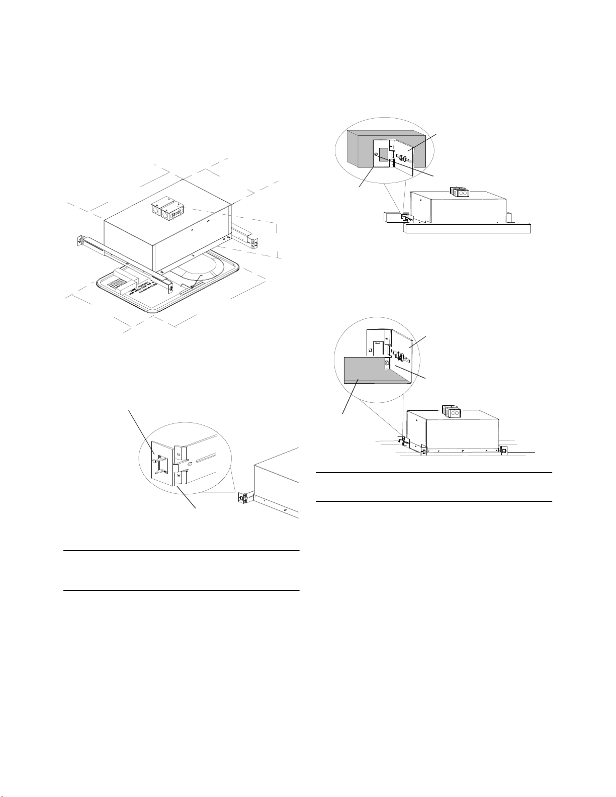
When installing luminaires lengthwise within a ceiling tile, the
following steps are suggested:
1. Using luminaire housing as template, center housing in tile
and trace outline. Cut hole in tile. Opening must not be
more than 1” (25mm) larger than housing.
2. Place tile in recessed ceiling support track where luminaire is
desired.
3. Center and attach mounting bracket extension to short sides
of housing.
aRemove four of five screws from short side of luminaire
housing where frame attaches to enclosure. Leave cen-
ter screw in place.
bCenter extension flange along short side of housing with
right angle pointing up and outward. Hole in center of
extension flange fits over center screw head.
cSecure extension flange to housing with screws removed in
step 3.a. above.
4. Position mounting brackets over extension flange at both
ends and secure bracket, extension, and housing together
with two screws per bracket.
5. From adjacent tile location, lower housing down onto tracks
and tile from above. Secure mounting bracket to support
track with set screw supplied.
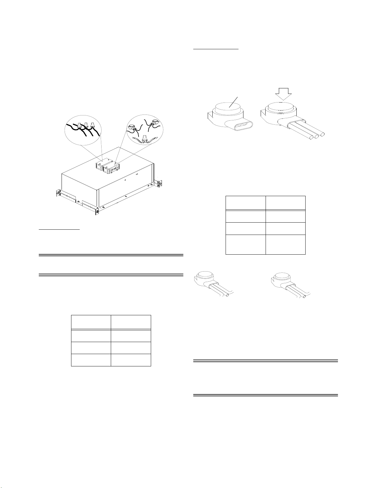
6. Connect AC power and data lines as described elsewhere in
this document.
Exposed Rafter Installations
When installing luminaire in an exposed rafter environment, it
will be necessary to attach the trim cover adapter to prevent light
leaks and assure proper trim cover fit.
Rough-In Housing Installation is now complete.
Luminaire is now ready for final installation.
To perform final installation, see: Final Installa-
tion Sheet for AR6RRecessed Luminaire (part
number 7093M1003).
GENERAL INFORMATION
Description
The AR6 Recessed luminaire is a specialized interior lighting
instrument which offers numerous state-of-the-art features such
as patented computer control of light, color, and pattern projec-
tion.
Frame
Enclosure
Extension
Mounting
Bracket
Other manuals for IRIDEON
1
Other ETC Industrial Equipment manuals
Popular Industrial Equipment manuals by other brands

Nordco
Nordco C Installation, operation and maintenance manual

OmniOn Power
OmniOn Power G391 quick start guide

PCB Piezotronics
PCB Piezotronics HT356A01 Installation and operating manual

Simpro
Simpro Ezi-MT user manual

ABB
ABB Tmax PR232 Getting started

KMT
KMT STREAMLINE SL-V SRP 100 Operation and maintenance manual