SCMI SUPERSET XL Installation guide

USO E MANUTENZIONE
OPERATION AND MAINTENANCE
FONCTIONNEMENT ET ENTRETIEN
BETRIEBS- UND WARTUNGSANLEITUNG
USO Y MANTENIMIENTO
SUPERSET XL
SCORNICIASCORNICIA
SCORNICIASCORNICIA
SCORNICIATRICE ATRICE A
TRICE ATRICE A
TRICE AUTUT
UTUT
UTOMAOMA
OMAOMA
OMATICATICA
TICATICA
TICA
AUTOMATIC PLANING AND MOLDING MACHINE
MOULURIERE AMOULURIERE A
MOULURIERE AMOULURIERE A
MOULURIERE AUTUT
UTUT
UTOMAOMA
OMAOMA
OMATIQTIQ
TIQTIQ
TIQUEUE
UEUE
UE
PRPR
PRPR
PROFILFRÄSAOFILFRÄSA
OFILFRÄSAOFILFRÄSA
OFILFRÄSAUTUT
UTUT
UTOMAOMA
OMAOMA
OMATT
TT
T
MOLDURERA AMOLDURERA A
MOLDURERA AMOLDURERA A
MOLDURERA AUTUT
UTUT
UTOMAOMA
OMAOMA
OMATICATICA
TICATICA
TICA
(USA)(USA)
(USA)(USA)
(USA)
Questo manuale è da conservare per futuri riferimenti e dovrà sempre seguire la macchina
This manual is to be kept for future reference and must always accompany the machine.
Ce manuel doit être conservé pour de futures références et devra toujours suivre la machine.
Das Handbuch ist für künftigen Gebrauch aufzubewahren und muß stets die Maschine begleiten.
Este manual tiene que conservarse para futuras referencias y tiene que estar junto con la máquina.
0000571057C 1-1

1.1
SUPERSET XL CNusa1
GENERAL INFORMATION
PagineTotalicompresacopertrinaeretroN°105
Data
N°Bolla
Firma N° Modifica N°Bolla
Data N°
LIBRETTOUSOeMANUTENZIONE
SUPERSET XL
SCMIcannotbeheldresponsiblefordamagesresultingfromusenotdescribedinthismanualorfromimproper
maintenance.
Contactyourlocaldealerforanyrequirementsoradviceonuse.
MACHINE OPERATORS
Personnel who will be working on the machine must, apart from being professionally trained for the job, read
the manuals paying particular attention to the safety regulations and the paragraphs relative to his area of
competence.
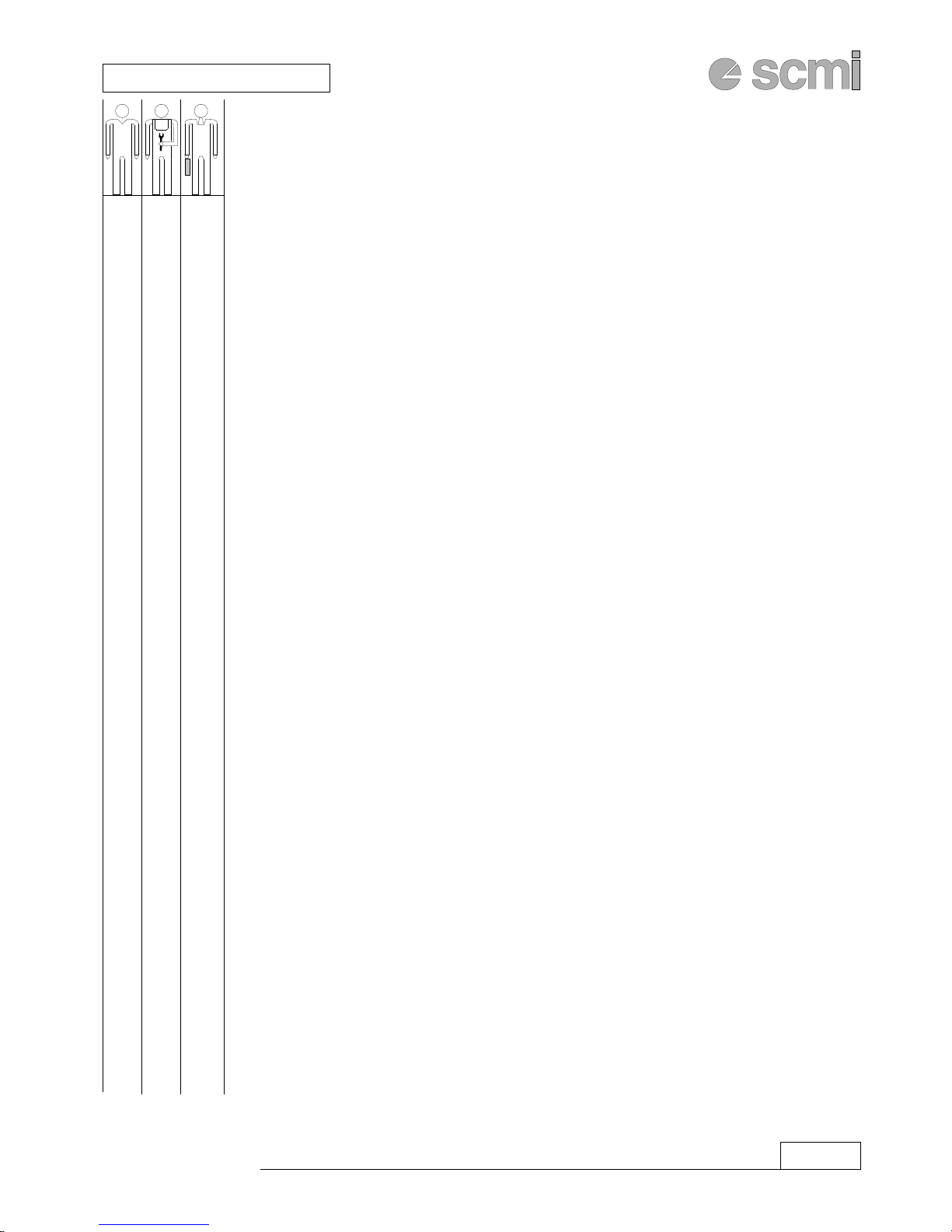
The machine operators are identified as follows:
PRODUCTION OPERATOR - responsible for production
EXPERT OPERATOR - responsible for machine tooling and set-up
MAINTENANCE OPERATOR - responsible for machine maintenance
B11331
01/10/99
12/01/99
0000571057C
S.I.T./R.L.(05)

1.2 CNusa1 SUPERSET XL
GENERAL INFORMATION
çThese paragraphs address:
XXX
XX
XX
XX
XXX
XXX
XXX
XX
XX
XX
XXX
XX
XX
XX
X
X
X
XXX
XXX
XXX
XXX
XXX
XX
X
X
X
X
X
X
X
X
X
GENERAL INFORMATION...............................................SECTION 1
Machineoperators ........................................................................................... 1.1
1-1 CORRESPONDENCE .................................................................................... 1.4
1-2 RECOMMENDATIONS ................................................................................. 1.4
1-3 MACHINE IDENTIFICATION ....................................................................... 1.5
1-4 CONDITIONS OF USE AND CONTRAINDICATIONS .............................. 1.5
1-5 CONCEPTS OF USE RELATED TO THE OPERATOR ................................. 1.6
1-6 SAFETYWARNINGS..................................................................................... 1.7
1-7 TECHNICALCHARACTERISTICS............................................................... 1.9
1-8 NOISE LEVEL ................................................................................................ 1.12
1-9 OVERALL DIMENSIONS.............................................................................. 1.13
1-10 WORK AREAS AND STATIONING.............................................................. 1.14
INSTALLATION................................................................... SECTION 2
2-1 MACHINEUNLOADING .............................................................................. 2.2
2-2 POSITIONING................................................................................................ 2.2
2-3 LEVELLING .................................................................................................... 2.2
2-4 ELECTRICAL CONNECTION ANDEARTHING......................................... 2.4
2-5 CONNECTION TO SUCTION SYSTEM...................................................... 2.6
2-6 PNEUMATIC CONNECTION ....................................................................... 2.8
2.7 SAFETYDEVICES USED .............................................................................. 2.10
USE AND ADJUSTMENTS................................................ SECTION 3
3-1 CONTROL PANEL ......................................................................................... 3.2
3-2 STARTING THEMACHINE ........................................................................... 3.11
3-3 STOPPING THE MACHINE .......................................................................... 3.11
3-4 EMERGENCYSTOP ...................................................................................... 3.11
3-5 AUTO-BRAKINGMOTOR............................................................................ 3.12
OPERATING UNITS ..............................................................SECTION 4
4.1 TOOL ADJUSTMENT AND LOCKING ON SPINDLES ........................... 4.2
4.2 OPERATING UNITS ..................................................................................... 4.6
4.2.1 BOTTOM HORIZONTAL SPINDLE.................................................................... 4.6
4.2.2 RIGHT VERTICAL SPINDLE .............................................................................. 4.8
4.2.3 LEFT VERTICAL SPINDLE................................................................................. 4.10
4.2.5 TOP HORIZONTAL SPINDLE ............................................................................. 4.12
4.2.6 SECOND BOTTOM HORIZONTAL SPINDLE................................................... 4.14
4.3 TOP MOBILE UNIT...................................................................................... 4.16
4.4 INLETGUIDEAND TABLE .......................................................................... 4.18
4.5 UNIVERSAL SPINDLE UNIT..........................................................................4.20
1.3
SUPERSET XL CNusa1
GENERAL INFORMATION
çThese paragraphs address:
X
X
X
X
X
X
X
X
X
X
X
X
XXX
X
X
XX
XX
XX
XX
XX
XX
XXX
XX
XXX
XX
ADJUSTMENT AND USE OF OPTIONAL UNITS ......SECTION 10
10.1 KNIFE ADJUSTMENTDEVICE ................................................................. 10.2
10.2 TANDEM FEED UNIT IN FRONT OF RIGHT VERTICALSPINDLE ...... 10.2
10.3 VERTICALPRESSER .................................................................................. 10.4
10.4 ADDITIONALEQUIPMENT FOR NARROW PIECES ............................. 10.4
10.5 MANUALLYOPERATEDTABLE LUBRICATIONPUMP......................... 10.6
10-6 AUTOMATICTABLE LUBRICATIONPUMP ............................................ 10.6
10-7 METRECOUNTER...................................................................................... 10.8
10-8 HOURCOUNTER ....................................................................................... 10.8
10-9 TW0-SECTORPRESSURE SHOE POSITIONED AFTER THE UNIT ...... 10.10
AUTO-BRAKING MOTOR.................................................SECTION 19
19-1 AUTO-BRAKING MOTOR...................................................................... 19.2
19-2 “ELETTRO ADDA” AUTO-BRAKING MOTOR ................................. 19.4
19-3 “LAFERT” AUTO-BRAKING MOTOR.................................................. 19.6
MAINTENANCE ..................................................................SECTION 20
20-1 MACHINE CLEANING .............................................................................. 20.2
20-2 PERIODIC LUBRICATION ........................................................................ 20.2
20-3 PNEUMATIC SYSTEM .............................................................................. 20.4
20-4 BOTTOM HORIZONTAL OPERATING UNIT BELT TENSIONING ..... 20.6
20-5 TOP HORIZONTAL OPERATING UNIT BELT TENSIONING .............. 20.6
20-6 RIGHT VERTICAL OPERATING UNIT BELT TENSIONING ............... 20.6
20-7 LEFT VERTICAL OPERATING UNIT BELT TENSIONING .................. 20.8
20-8 OPERATING UNIT BELT REPLACEMENT ............................................ 20.8
20-9 VARIATOR TIMING BELT REPLACEMENT .......................................... 20.10
20-10 INSPECTION OF SAFETY DEVICES ...................................................... 20.10
20-11 REMOVAL - STORAGE - DEMOLITION ................................................ 20.11
20-12 EMERGENCY CONDITIONS ................................................................... 20.11
20-13 TROUBLESHOOTING ............................................................................... 20.12

1.4 CNusa1 SUPERSET XL
GENERAL INFORMATION
1-1 CORRESPONDENCE
WhenwritingorphoningthedealerorSCMIforanyreasonconcerningthemachine,alwayssupplythefollowing
information:
1) Machinemodel
2) Serialnumber
3) Voltage and frquency
4) Date of purchase
5) Name of dealer where the machine was purchased
6) Detailed description of any faults found
7) Detailed description concerning the specific machining to be carried out
8) Period of use - number of hours of operation
Manufacturer’saddress
SCM GROUP USA INC.
SCM I DIVISION
2475SatelliteBlvd
SuiteB
Duluth,GA30136
Tel. 001-770-8138818 - Fax. 001-770-8138819
E-mail:[email protected]
1-2 RECOMMENDATIONS
Indrawingupthismanualalltheoperationsrelativetoregularmaintenancehavebeentakenintoconsideration.
It is recommended not to carry out any operation not described in this manual.
All operations requiring assembly or disassembly of parts must be carried out by authorised technicians.
The machine may only be used by trained personnel aware of the risks connected with its use.
Observetheaccident-preventionregulationsandtherulesofsafety andindustrialmedicineinforceinthecountry
where the machine is used.
Note:
- Torequestinformationconcerningtheelectricalsystem,providethedatalistedontheplatebelow,locatedon
theinsideoftheaccessdoortotheelectriccompartment.
FORNIT. Company which has executed the electrical system
DATA Dateofconstructionofelectriccontrolunit
CODICEDISTINTA Electricalcomponentlistnumber
N. Wiringdiagramnumber
VOLT RETE Machinepower supplymainsvoltage(V)
VOLTAUX Auxiliarycircuitspowersupplyvoltage(V)
VOLTFRENO Motorbrakepower supplyvoltage(V)
Hz Electrical frequency in Hz
FASE Number of power supply phases
MACCH. / TIPO Machine type CODICE
SCHEMA
FORNIT.
TIPO DATA
VOLT
RETE Hz kW FASI
DIS. CODICE
A

1.5
SUPERSET XL CNusa1
GENERAL INFORMATION
1-3 MACHINE IDENTIFICATION
The machine is identified by the punched text on the metallic plate located on the side of the base.
1.2
Ref.
Mod. Machine model
Matr. Serial number
Ref. Internal reference
Comp. No. of machine composition
N Gross weight expressed in Newton
kg Weight
Un Nominal electric voltage expressed in Volt
~ F Number of phases
Hz Electrical frequency in Hz
In Rated current in Amperes
1-4 CONDITIONS OF USE AND CONTRAINDICATIONS
Thismachinemustonlybeusedforcuttingofwoodorsimilarmaterials.“Similarmaterials”meansmaterialswith
technological and physical characteristics similar to those of wood for which the machining mechanism and
shavingremovalissimilar.
Materials different from those quoted above, not being assimilated with wood, are consequently excluded.
Wood or similar materials must be without foreign bodies (e.g. nails, stones, etc.).
Any damage caused by machining them shall be the sole responsibility of the user.
DIMENSIONSOFTHEPIECETOBEMACHINED
Themaximumdimensionsofthemachinedpiecesare: ................................... height120(*) mmxwidth230(**)mm
Consideringthatthemaximumremovalis10mm,themaximumdimensionofthepiecestobemachinedmaybe:
height 140mmxwidth250mm
With the option to remove from 10 mm to 0.1 mm, the minimum dimension of the machined piece
maybe: ................................................................................................... height6(1) mmxwidth25(2) mm
Theminimumlengthofthepiecewithsinglefeedis: .............................................................................. 620(3) mm
(*) with 145 mm ø tool mounted on the top horizontal unit
(**) with 145 mm ø tool mounted on the left vertical unit
with 125 mm ø tool mounted on the left vertical unit of machine with electronic control (optional).
(1) with positioning through electronic control (optional).........................................minimum height10mm
(2) with relevant optional (kit for minimum working width) ..................................... minimum width15mm
(3) with relevant optional (reduction of traction distance between centres) ............minimumlength450mm
USABLE TOOLS
Themachinehasbeendesignedforexclusiveuseoftoolsinconformitytosafetycurrentstandardsofthecountryinwhich
theywillbeused,suitableforthetypeofmaterialtobemachined.
ThelinkbetweenthetooldiameterandthetoolheightatparityofrotationspeedisdefinedinthetableinChapter4.1.
ENVIRONMENT
Themachinemaybeoperatedinthefollowingambientconditions:
Humidity: max. 90%
Temperature: min. +1°C max. +40°C
Altitude: max. 1,000 m above sea level (over this level consult the manufacturer)
The machine may only be operated in closed environments.
The machine may not be operated in explosive environments.
N

1.6 CNusa1 SUPERSET XL
GENERAL INFORMATION
PROHIBITIONSOFUSE
It is prohibited to:
- use the machine in a way different from that specified;
- use the machine without the protections provided for each machining operation, or with only part of them;
- use rotating operating units to assist piece feed;
- use materials different in type and dimensions from those already stated;
- usetoolsnotinconformitytosafetycurrentstandardsofthecountryinwhichtheywillbeused,orwithincompatible
dimensions(seetableinChapter4.1);
- make modifications to the machine.
Any damage deriving from improper use is the sole responsibility of the user.
RESIDUAL RISKS
Despiteobservance of thesafety regulations and use according to the rulesdescribed in thismanual, the
following residual risks may still be present:
- With the machine in manual mode, some of the protections are necessarily lacking, e.g. the
horizontally-pivoted protection open, to allow tooling and machine set-up (expert operator task).
- Possible collision of tools with other machine parts during adjustment (expert operator task).
- Contact with the tool
-Contactwithrotatingelements,suchasbelts,toolspindles,pulleys,tractionandmotiontransmission
devices.
-Danger of generating sparks in case of contact between rotating tools and foreign bodies.
- Hazard due to inhalation of dust in case of working with inadequate aspiration.
- Hazard due to exposure to noise.
- Danger of electric shock from live elements.
- Piece recoil at inlet until it is dragged by the traction wheels.
- Possible risk of getting trapped and/or sheared if the user adds conveyors or sliding tables at the
machine outlet.
1-5 CONCEPTS OF USE RELATED TO THE OPERATOR
On the control panel there is one or more key selectors.
These selectors enable use of the machine according to precise settings and safe operating logic.
Only the expert operator may drive these selectors; improper use may cause precarious conditions of use and
dangerous situations.
On completion of the necessary adjustment and set-up operations to which the selectors give access, the
expertoperatormustextractthekeysfromthecontrolpanelandauthorisetheproductionoperatortouse
themachine.
Itisalsoindispensabletohave2suitablepadlocksavailabletolockthemainswitchoftheelectricalpowersupply
and the main valve of the pneumatic system (if present).
The door of the electric box is closed with one or more locks. The key to open the box is provided with the
machine. In normal operating and maintenance conditions the door must always be closed.
Theexpertoperatorisresponsibleforandcustodianofallthekeys.

1.7
SUPERSET XL CNusa1
GENERAL INFORMATION
1-6 SAFETY WARNINGS
Carefully read this instruction manual before starting the machine.
Observe all the instructions, warnings and danger signs affixed to the machine and check that these are always
maintainedintactandperfectlylegible.
Thismachinehasbeenconstructedtooffermaximumsafety,distinguishedatthetimeofitsconstruction,together
with best performance.
Arbitrarymodificationsmadetothemachineshallrelievethemanufacturerofanyliabilityfordamages
which may derive from it.
PROCEDURES FOR WORKING SAFELY
- Aclearworkingareaaroundthemachineisfundamentalforsafety:thefloormustbeflat,well-keptandfree
of material, e.g. shavings, scraps, etc.
- Sufficient lighting must be provided, general or localised at the workstation, min. 300 LUX.
- Be careful with objects which may cause accidents: take off rings, watches, bracelets and ties, tie sleeves
around the wrists and tie up hair.
- Wear clothing in conformity with the safety regulations including:
- suitable shoes as per the safety regulations;
- hearing protection;
- respiratory tract protection;
- protective glasses or screens;
- gloves to handle tools and raw materials;
- The operator must never leave the machine unattended during operation.
- Duringcleaning, maintenance, identification and correction of faults,thesafety procedures provided must
beapplied.
- The Use-Maintenance manual must be kept near the machine so that it may be consulted at any time.
FOR ALL TOOL CHANGE, CLEANING OR MAINTENANCE OPERATIONS, SET ALL THE
SWITCHES TO ZERO AND PADLOCK THEM.
OPERATOR TRAINING
It is important that all the operators receive adequate training, which includes information relative to the
dangers associated with use of the machine and the precautions to take. In particular:
- themachine operatingprinciples, properuse, correctuseof theprotections whichmust periodicallybe
checked.
- how to handle the pieces at the time of use;
- the position of the hands before, during and after machining.
The operators must furthermore be trained for firefighting operations.
GUARDS
The machine must not be used if all the guards and other safety devices necessary for machining are not in
position, in good operating condition and have not undergone proper maintenance.
NOISE
The operator must be informed concerning the noise levels which may be generated during normal use of
the machine and the factors which affect the exposure to noise. The factors include:
- correct tool selection;
- correct speed selection;

1.8 CNusa1 SUPERSET XL
GENERAL INFORMATION
- toolandmachinemaintenance;
- typeofmaterialmachined;
- importanceanduseofallthefencesprovided;
- properuseofpersonalprotection(headsets,earplugs,etc.).
DUST
Theoperatormustbeinformedconcerningtheriskscausedbyexposuretodustandthefactorswhichaffect
exposure. These factors include:
- tooland machinemaintenance;
- relation between cutting speed and feed speed;
- typeof materialmachined;
- importance of local aspiration on each operating unit (dust collection at source);
- proper adjustment of hoods, deflectors, hoppers;
- proper use of personal protection (masks, etc.).
The suction system must be connected to the machine and operational before starting machining.
DO NOT USE COMPRESSED AIR TO REMOVE DUST AND SHAVINGS.
MACHINE SAFETY
- The machine must not be used if the guards and safety devices are not active, in position, in good
conditionand properly maintained.
- Neverworkpiecesofdimensionsnotsuitedtothemachinecapacity(seedimensionsofmachinedpiece
in paragraph 1.4).
- Before mounting any tool, ensure that the mortising surfaces are well-cleaned and without dents.
SAFETY DURING MAINTENANCE
- UseonlyoriginalSCMIspareparts.
- When maintenance operations need to be carried out, stop the machine, set the main electrical and
pneumatic switches to zero and padlock them.
- Completelystopthemachineandensurethatthetoolsarestandingstillbeforeproceedingwithcleaning
or maintenance and before removing any protection for cleaning, inspection or maintenance.
- Carry out a routine check of the signalling devices of the electric panel: one by one switch on the tool
motor of each unit and check on the electric panel that the corresponding pilot light is on.
- Regularlyandsystematicallycheck theefficiency ofeach safetydevice.
TOOLS
- Exclusivelyusetoolsinconformitytosafetycurrentstandardsofthecountryinwhichtheywillbeused.
- Follow the instructions of the manufacturer for use, adjustment and repair of the tools.
- The speed limit (number of revolutions/min.) marked on the tool must not be exceeded.
- Ensure that the tools are perfectly balanced and sharpened and accurately splined and tightened.
- Never use cracked or deformed tools.
- Ensure that the spacing rings and the flanges are suitable for use as declared by the manufacturer.

1.9
SUPERSET XL CNusa1
GENERAL INFORMATION
1-7 TECHNICAL CHARACTERISTICS
Max. working width (finished section) ............................................... 230 mm(OPT 240 mm)
Min. working width (finished section) .................................................. 25 mm (OPT 15 mm)
Max. working height (finished section) ....................................................................... 120 mm
Min. workingheight (finishedsection) ........................................................................... 6 mm
Minimumlengthofsinglepiece ..............................................620 mm (OPT 450 mm)
Feed speed ....................................5÷25m/min(OPT6÷36m/min)
Spindle rotation speedi ..................................... 6000 RPM (OPT 8300 RPM)
Spindlediameter .................................. 40 mm (OPT 50mm o 1"13/16)
Usefullengthofvertical spindles ...............................................140 mm (OPT180 mm)
Usefullength ofhorizontal spindles ....................................................................... 250 mm
Universalspindlelength ....................................................................... 240 mm
Axialadjustment ofverticalspindles with
respect to the table ..................................................................... 0÷80 mm
Axialadjustment of horizontal spindles with
respect to the right guide ..................................................................... 0÷45 mm
Axial adjustment of the planer spindle ..................................................................... 0÷45 mm
Minimumand maximumdiameterof profilingtool ................................................................100-200 mm
Minimum and maximum diameter of tools
onplaner spindle ................................................................120-140 mm
Profile capacity on 2nd bottom horizontal unit
with 200 mm ø tool ......................................................................... 15 mm
Motor power of tool-holder spindles ........................................... 4 kW (OPT up to 15 kW)
Feed motor power .............................................................3 HP (2,2 kW)
Feed roller diameter ....................................................................... 140 mm
Inlet table length ........................................... 2000 mm(OPT 2500 mm)
Quick adjustment for inlet guide and table ......................................................................... 10 mm
Net weight composition 1 ....................................................................... 2200 kg
Netweightcomposition 5 ....................................................................... 2350 kg
Netweightcomposition 2 ....................................................................... 2900 kg
Netweightcomposition 6 ....................................................................... 3050 kg

1.10 CNusa1 SUPERSET XL
GENERAL INFORMATION
Optionals
Optionals for feed systemo
- Pneumatic cut-out from control panel for feed unit located before the planer spindle
- Horizontal presser before planer with pneumatic cut-out from control panel.
- Tandem feed unit in front of right vertical unit with rapid cut-off.
- Tandem feed unit in front of universal unit with rapid cut-off.
- Traction wheels flanged in correspondence to the left vertical unit with manual horizontal movement.
- Supplementary vertical roller presser
- Supplementary steel feed roller, 140 x 25 mm
- Supplementary flanged steel feed roller, 140 x 25 mm
- Supplementary rubber feed roller, 140 x 25 mm
- Supplementary flanged rubber feed roller, 140 x 25 mm
- Supplementary knurled feed roller, 140 x 25 mm
- Supplementary flanged knurled feed roller, 140 x 25 mm
Optionals for table and guides
- Hardened insert on inlet table
- Chrome-plated antiwear work tables
- Grooved tables
- Supplementary tables with Rexilon inserts
Optionals for universal spindle unit
- Front and rear pressure pads to be applied on the hood
- Vertical pad presser to use the universal spindle from underneath
- Fitting on supplementary hood for glass stop recovery on the left side
- Static inverter to machine with continuously variable rotation speed from 1000 to 6000 rpm.
- Supplementary suction hood for blade of max. 250 mm.
Various optionals
- “Control 10 Plus” microprocessor electronic control. Allows automatic positioning from the control panel of the left vertical and
the top horizontal units for the different work sections.
- Automatic adjustment device for left vertical spindle to machine pieces of different width in rapid succession.
- Micrometric horizontal adjustment of working width.
- Front presser on hood of top horizontal with parallelogram movement.
- Two-sector pressure shoe located after the top horizontal spindle.
- Kit for glass stop cutting on right side by means of top horizontal spindle.
- Fitting for vertical cut with several blades with second bottom horizontal unit
- Safety device by means of anti-return breaker arms located at the machine inlet.
- 25 HP (18.5 kW) motor for second bottom horizontal unit.
- Inlet guide with bearings for automatic feeders.
- Electrical fitting for use of automatic loaders.
- Pump for work table lubrication with manual drive.
- Pump for work table lubrication with automatic drive.
- Manual centralised lubrication.
- Hour counter for hours of service.
- Metre counter with reset.
- Lighting inside the horizontally-pivoted protection.
-Auto-brakingmotor

1.11
SUPERSET XL CNusa1
GENERAL INFORMATION
COMPOSITIONS
Legend:
Bottom horizontal (planer) Top horizontal
Right vertical Left vertical Universal unit
Composition 1
Composition 2
Composition 5
Composition 6

1.12 CNusa1 SUPERSET XL
GENERAL INFORMATION
1-8 NOISE LEVEL
WARNING
The noise values are emission levels and not necessarily safe working levels. Although there is a correlation
betweentheemissionlevelsandtheexposurelevels,itcannotreliablybeusedtodeterminewhetherornotfurther
precautions are required. The factors affecting the real exposure level include the duration of exposure, the
ambientcharacteristics,othersourcesofemission,suchasthenumberofmachinesandotheradjacentmachining
operations.
The exposure levels may also vary from country to country.
However, this information allows the user of the machine to make a better evaluation of the dangers and risks.
Some factors which reduce exposure to noise are:
- Correct tool selection
- Correct speed selection
- Tooland machine maintenance
- Use of the anti-noise covers and protections supplied
- Proper use of hearing protection
Planing and profiling machine model: SUPERSET XL
As per test report: CSR No. 99033
Operating conditions: Planing
Reference norm: ISO 3746/79
Other reference regulations: ISO 7960/95 Annex H UNI EN ISO 11201-97
In idle without suction Running
Sound power
level emitted
dB W (A) [mW (A)] 88.4 [ 0.69 ] 101.5 [ 14.19 ]
Sound pressure level
at operator work
station inlet
dB (A) [dB max]
76.5 90.5 [ 101.1]
Sound pressure level at
operator work station
outlet
dB (A) [dB max]
68.6 84.4 [ 94.8 ]
Constant K = 2 [dB] according to prEN 12750
The above values are referenced to "free range" conditions in compliance with the
test methods as provided by the reference norm.

1.13
SUPERSET XL CNusa1
GENERAL INFORMATION
1615
3496 (*)
866 (*)
900
1600
57
1615
1600
4296 (*)
57
866 (*)
1145
1145
900
900
1-9 OVERALL DIMENSIONS
COMPOSITIONS1AND5
(*)+500mmwithoptional2500mminlettable
COMPOSITIONS2AND6
(*)+500mmwithoptional2500mminlettable
1.14 CNusa1 SUPERSET XL
GENERAL INFORMATION
A
BC
C
*
*
min. 1000 mm
min. 1000 mm
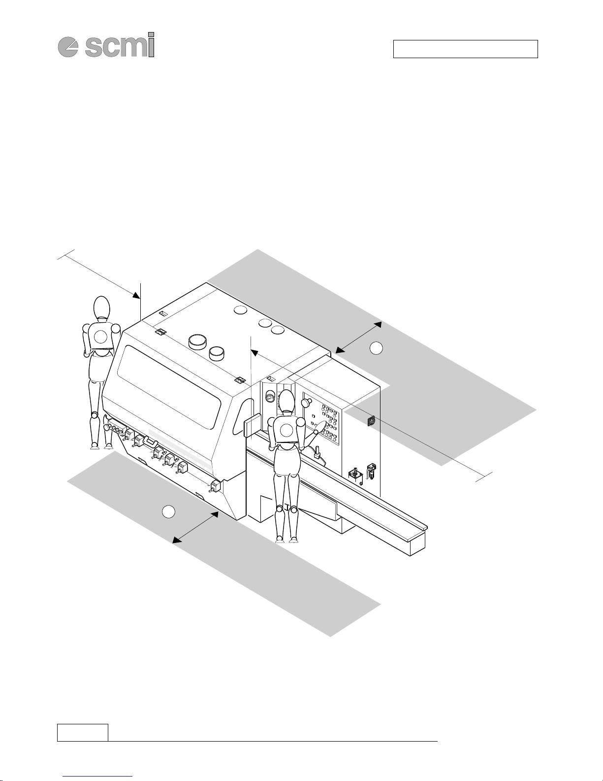
1-10WORK AREAS AND STATIONING
Legend:
A-Controlstationandinsertionofmaterialtobemachined
B-Machinedmaterialunloadingstation
C-Outercontrolareaorpedestrianpassage
NOTE:Thedistance*mustbe800mmlongerthanthelongestpiecetobemachined
CAUTION: Failingtorespecttheminimumfreespacesmaycreatedangerousconditionsfortheoperatorandthe
personnelaroundthemachine.Donotdepositgoodsofanykindwithinthezonelimits.

2.1
SUPERSET XL
INSTALLATION
cnusa2
SECTION2
INSTALLATION
2-1 MACHINEUNLOADING ............................................................................................................... 2.2
2-2 POSITIONING................................................................................................................................. 2.2
2-3 LEVELLING ..................................................................................................................................... 2.2
2-4 ELECTRICAL CONNECTIONANDEARTHING.......................................................................... 2.4
2-5 CONNECTION TO SUCTION SYSTEM....................................................................................... 2.6
2-6 PNEUMATIC CONNECTION ........................................................................................................ 2.8
2.7 SAFETYDEVICES USED ............................................................................................................. 2.10

2.2 cnusa2 SUPERSET XL
INSTALLATION
2-1 MACHINE UNLOADING
Before unloading the machine, remove all the parts used for transport or packaging.
Lift the machine with a crane or other hoisting means, hooking the cables fitted with hooks in the special
attachments(Bfig.2.1).Intheabsenceofsuitablehooks,cableswithslotmayalsobeusedforlifting;inthiscase
thehorizontally-pivotedprotectionmustbeopenedandthesplitpinsremovedfromthepivot.Removethepivots,
place the slots of the cables into position, re-insert the pivots and remount the split pins (C Fig. 2.1 – cable
attachmentsequence).
NOTE: Respect the cable lengths indicated in Fig. 2.1.
During lifting avoid tearing or sudden movements.
Asanalternativetotheinstructionsabove,themachinemayalsobeliftedwithaforklifttruckequippedwithforks
of suitable length, inserting the forks in the special openings indicated with plates (A Fig.2.1).
Adopteverycautiontoexcludeanypossibilityofthemachineturningover,securingitwithcablestothestructure
of the forklift truck.
Ensure that the crane, cables or lift truck have a capacity equal to or greater than the weight of the
machine.
Theweightisindicatedonthemachineidentificationplate (seepoint1-3).
2-2 POSITIONING
Selectthebestposition,withgoodlighting(500LUXminimumisrecommended),takingintoconsiderationthe
connectionstotheelectricline,thecompressedairsystem,thescrapsuctionsystem,andeasymaintenance.The
minimum free space around the perimeter of the machine must be 1000 mm, except in the operator zone for
starting and adjustments where it must be 1500 mm and at the operator work station at the outlet where the
distance must be equal to the maximum length of the machined piece plus 800 mm.
Checkthatthefloorsurfaceissolid(preferablyinnon-deformablematerial,acementfloorisrecommended),so
that the base may find a uniform support at the contact points.
Themachineisgreasedandoiledforreasonsoftransport.
Beforestartingwork,thoroughlyremovethegreasefromtheworkingareasandtheprotections.
Thebaseofthemachineisfittedwithspecialsupportfeetinsidewhichscrewsarefittedformachinelevelling.
2-3 LEVELLING
Position the machine as convenient, and rest a high-precision level (0.05 mm per meter) on the ground table in
correspondencetoeachspindle,firstlongitudinallythentransversally,makingpreliminarycorrectionsbyacting
on the screws (m12x25 hexagonal head in the accessory pack) which have been inserted under the feet. The
supportbosses(PFig.2.1)suppliedintheaccessorypackarepositionedbetweenthescrewsandthefloor.
Againadjustthescrews,simultaneouslycheckingthevariationsproduced.An0.1mmplanarityerroristolerableas
maximumvalueovertheentirelengthoftheworktables.
For transversal levelling place the level near the first spindle and move it by successive sections of 300 mm.
The inlet table must be perfectly aligned with the fixed table of the machine. Misalignment in both directions
between the two tables must not exceed 0.1 mm.

2.3
SUPERSET XL
INSTALLATION
cnusa2
max 90°
≥≥
≥≥
≥1200mm
≥≥
≥≥
≥1400mm
BC
A
P
2.1
2.4 cnusa2 SUPERSET XL
INSTALLATION
2-4 ELECTRICAL CONNECTION AND EARTHING
Theelectricalconnectionandthetestslistedbelowmustalwaysbecarriedoutbyaspecialisedelectrician.
Ensurethattheelectriclineofthefactoryissufficienttosupportthepowerofthemachineandcheckthatthemainsvoltage
correspondstothatofthemachine.
Note: Theidealoperatingconditionforthemachineistosupplytheexactvoltageshownontheidentification
plate in Fig. 2.2; (tolerance ± 5%).
Out of this range, adjust the power supply voltage.
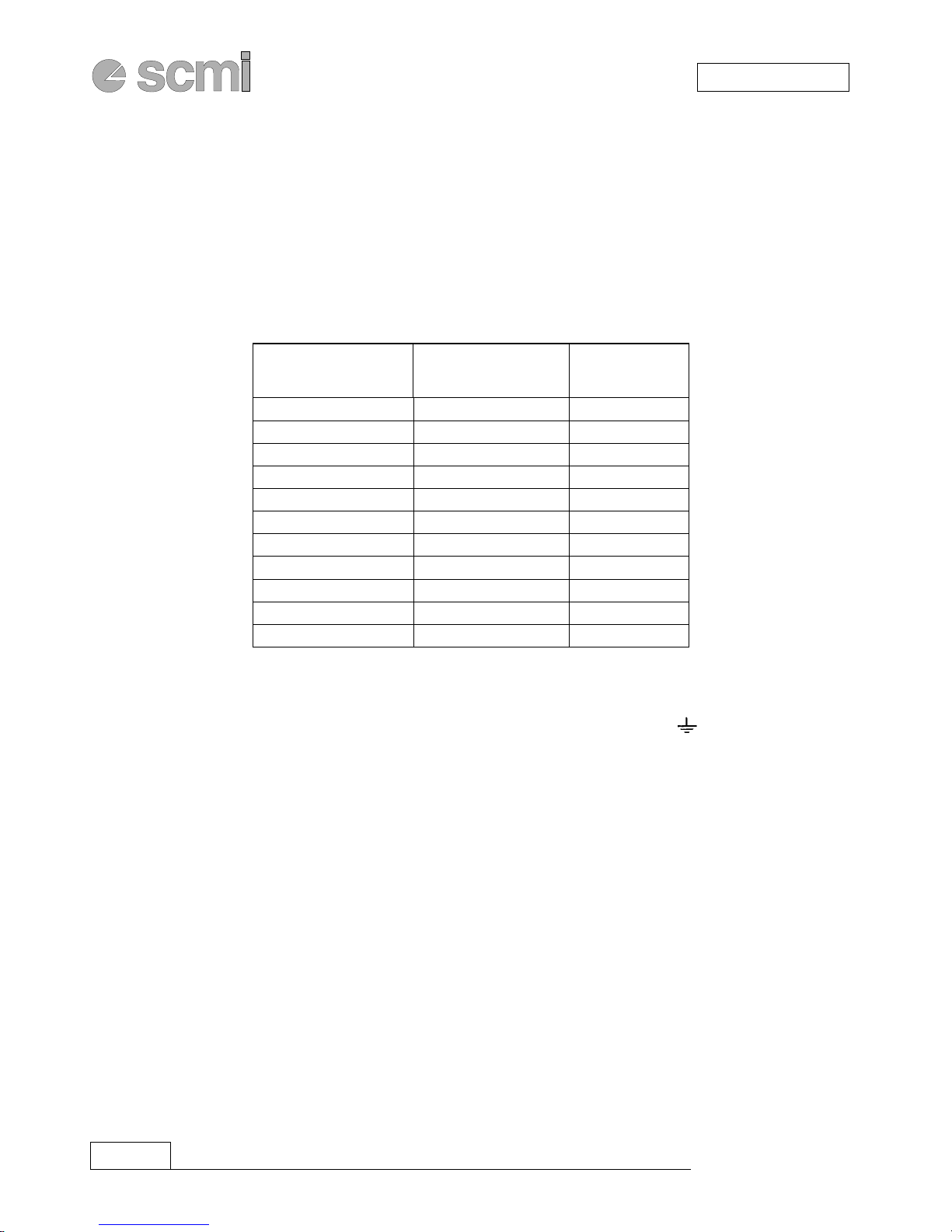
On the machine identification plate, read the value of the total absorbed current (Amp).
Then, referring to the table below select the cable cross-sections, and the fuses to install upstream of the
machine. The fuses are of the “DELAYED FUSE” (AM) type.
AMPERE ASSORBITI
ELECTRICAL INPUT (AMPERE)
AMPERES ABSORBES
STROMAUFNAHME (AMPERE)
AMPERE ABSORBIDOS
SEZIONE CAVI
CABLE SECTION
SECTION CABLE mm2
KABELQUERSCHNITT
SECCION CABLES
FUSIBILI AM
AM FUSE
FUSIBLE AM
SICHERUNGEN
FUSIBLES AM
fino a/up to/ jusqu'à /bis 10. 2.5 12 A AM
da/from/de/von 10 a/to/à/bis 14 4.0 16 A AM
da/from/de/von 14 a/to/à/bis 18 6.0 20 A AM
da/from/de/von 18 a/to/à/bis 22 6.0 25 A AM
da/from/de/von 22 a/to/à/bis 28 10.0 32 A AM
da/from/de/von 28 a/to/à/bis 36 10.0 40 A AM
da/from/de/von 36 a/to/à/bis 46 16.0 50 A AM
da/from/de/von 46 a/to/à/bis 54 16.0 63 A AM
da/from/de/von 54 a/to/à/bis 76 25.0 80 A AM
da/from/de/von 76 a/to/à/bis 92 35.0 100 A AM
da/from/de/von 92 a/to/à/bis 110 50.0 125 A AM
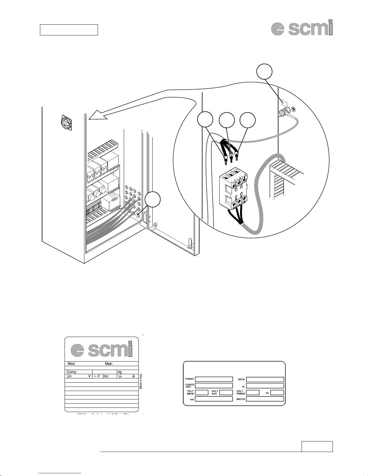
Electrically isolate the machine by setting the main switch to zero and connect the 3 electrical cables (phases)
to the terminals L1, L2, L3 as in Fig. 2.2.
Connecttheyellow-greencable(earth)totheterminal(PE)ormarkedwiththesymbol ,and theneutralcable,
if present, to the terminal (N).
Shouldthemachine beconnected toa mobilepower cable,use aflexible rubbercable markedwith thesymbols
H07RN-ForA07RN-Fhastobeinaccordancesafetycurrentstandardsofthecountryinwichitwillbeused.
The relevant coupling outlet must comply with the DIN 49463 regulation and the international regulations
IEC309-1andIEC309-2ortosafetycurrentstandardsofthecountryinwichitwillbeused.
Carefullylockthecableclamp(GFig.2.2). Checkthatthespindlerotationdirectioniscorrect(thespindlesmust
rotate in the opposite direction to the piece feed) by starting the machine as described further on.
If the spindles do not turn in the right direction:
- Disconnect the power
- Invert two phases on the terminal board
- Retest the rotation direction.
Warning!!!:In normal operating and maintenance conditions, the door of the electric box must always remain
closed. It may only be opened by a specialised electrician using the special key provided with the
machine and kept by the expert operator.
The complete wiring diagrams and certificates may be found in the accessory bag.
2.5
SUPERSET XL
INSTALLATION
cnusa2
L2 L3
L1
PE
Ref.
G
2.2
Table of contents
Other SCMI Industrial Equipment manuals

Popular Industrial Equipment manuals by other brands

Henkel
Henkel BONDERITE C-AK 9045-6 AERO Technical bulletin

Omron
Omron SYSMAC NX series Startup guide

permaban
permaban AlphaJoint installation guide

Festo
Festo CRHD Series Repair instructions

MILLART MACHINE TOOLS
MILLART MACHINE TOOLS TB-12 Operation manual

Siemens
Siemens SIMATIC ET 200SP HA Equipment manual


